JP2010077883A - Cooling equipment for engine - Google Patents
Cooling equipment for engine Download PDFInfo
- Publication number
- JP2010077883A JP2010077883A JP2008246539A JP2008246539A JP2010077883A JP 2010077883 A JP2010077883 A JP 2010077883A JP 2008246539 A JP2008246539 A JP 2008246539A JP 2008246539 A JP2008246539 A JP 2008246539A JP 2010077883 A JP2010077883 A JP 2010077883A
- Authority
- JP
- Japan
- Prior art keywords
- engine
- insertion hole
- outlet member
- return water
- pump unit
- Prior art date
- Legal status (The legal status is an assumption and is not a legal conclusion. Google has not performed a legal analysis and makes no representation as to the accuracy of the status listed.)
- Withdrawn
Links
Images


Landscapes
- Exhaust Silencers (AREA)
Abstract
【課題】戻り水路用配管を、差し込み式金属管とした場合、ポンプ周辺のスペースを広くせずに、ポンプのみをエンジンから取り外し可能なエンジン冷却装置を提供する。
【解決手段】列状配置の複数気筒を有するエンジンで、前部の側部に取り付けられエンジンへ冷却水を圧送するポンプ2と、エンジンの後部に設けられエンジン内を流通した冷却水が排出される出口部材と、出口部材からポンプへ冷却水を還流させる金属製の戻り配管3とを備えたエンジンの冷却装置で、ポンプ側差込孔21は、エンジンの気筒列方向後部へ向けて開口すると共に、深さ方向が所定方向であり、出口部材側差込孔11は、エンジンの気筒列方向前部へ向けて開口すると共に、深さ方向が所定方向と同一又は平行であり、ポンプをエンジンから取り外す際、戻り水路用配管を出口部材側差込孔側へシフト可能なように、通常時の戻り水路用配管の他方端部の差込量よりも深くする。
【選択図】図2To provide an engine cooling device in which only a pump can be detached from an engine without widening the space around the pump when the return water pipe is a plug-in metal pipe.
In an engine having a plurality of cylinders arranged in a row, a pump 2 attached to the front side of the engine and pumps cooling water to the engine, and cooling water provided at the rear of the engine and flowing through the engine are discharged. The pump side insertion hole 21 opens toward the rear in the cylinder row direction of the engine. The cooling device for the engine includes an outlet member and a metal return pipe 3 that recirculates cooling water from the outlet member to the pump. In addition, the depth direction is a predetermined direction, the outlet member side insertion hole 11 opens toward the front in the cylinder row direction of the engine, and the depth direction is the same as or parallel to the predetermined direction. When removing from the pipe, the return water pipe is made deeper than the insertion amount at the other end of the return water pipe at the normal time so that the return water pipe can be shifted to the outlet member side insertion hole.
[Selection] Figure 2
Description
本発明はエンジンの冷却装置に関し、特に、戻り水路用配管回りの配管構造に関する。 The present invention relates to an engine cooling apparatus, and more particularly to a piping structure around a return water pipe.
多気筒エンジンの冷却装置として、エンジンの気筒列方向前部にポンプユニットを配置してエンジン内に冷却水を圧送し、エンジンの気筒列方向後部から冷却水を排出してポンプユニットへ冷却水を還流することで、冷却水を循環するものが知られている。 As a cooling device for a multi-cylinder engine, a pump unit is arranged at the front part in the cylinder row direction of the engine, the cooling water is pumped into the engine, the cooling water is discharged from the rear part in the cylinder row direction of the engine, and the cooling water is supplied to the pump unit. What circulates cooling water by recirculating | refluxing is known.
エンジン後部からポンプユニットへ冷却水を還流する戻り水路用配管の構成としては、例えば、ゴムホースを用いたものが周知である。しかし、ゴムホースは、ポンプユニット等の他の構成との接続に関し、ホースバンド等が必要であり、組み付け作業に手間がかかるという問題がある。また、戻り水路用配管がエンジンの排気側に位置する場合、ゴムホースの選定にあたって、その耐熱性も考慮する必要があり、利用可能なゴムホースに制約も生じ得る。 As a structure of the return water pipe for returning the cooling water from the rear part of the engine to the pump unit, for example, one using a rubber hose is well known. However, the rubber hose has a problem that a hose band or the like is required for connection with other components such as a pump unit, and the assembling work is troublesome. In addition, when the return water pipe is located on the exhaust side of the engine, it is necessary to consider the heat resistance when selecting the rubber hose, and there may be restrictions on the available rubber hose.
そこで、戻り水路用配管として、金属管を用いたものが提案されている(特許文献1)。金属管を用いたものでは、ポンプユニット等の他の構成との接続に際し、相手側に差込孔を設け、差込孔と金属管との間をOリング等のシール部材でシールした差し込み方式を採用することで、組み付け作業が簡素化する。また、戻り水路用配管がエンジンの排気側に位置する場合、その耐熱性も通常十分である。 Therefore, a pipe using a metal pipe has been proposed as a return water pipe (Patent Document 1). In the case of using a metal pipe, when connecting to other components such as a pump unit, an insertion hole is provided on the other side, and the insertion hole and the metal pipe are sealed with a sealing member such as an O-ring. By adopting, assembly work is simplified. Also, when the return water pipe is located on the exhaust side of the engine, its heat resistance is usually sufficient.
ここで、ゴムホースと異なり金属管は可撓性に富んでいない。このため、メンテナンス等でポンプユニットだけをエンジン本体から取り外したい場合、金属管が邪魔になり、ポンプユニットの差込孔に対する金属管の差込量分だけポンプユニットを差し込み方向に移動して、金属管からポンプユニットを取り外す必要がある。 Here, unlike the rubber hose, the metal tube is not very flexible. For this reason, if you want to remove only the pump unit from the engine body for maintenance, etc., the metal pipe will get in the way, and the pump unit will move in the insertion direction by the amount of insertion of the metal pipe into the insertion hole of the pump unit. It is necessary to remove the pump unit from the pipe.
しかし、エンジンルーム内においてポンプユニット周辺のスペースには限りがあり、エンジンルーム内のレイアウト上、ポンプユニットを、上記差込量分だけ差し込み方向に移動できない場合がある。この場合、金属管回りの構成を分解しなければポンプユニットをエンジン本体から取り外すことができず、メンテナンス性が劣る。また、ポンプユニットを、上記差込量分だけ差し込み方向に移動できるようにポンプユニット周辺のスペースを広くすると、エンジンルームの小スペース化を妨げることになる。 However, the space around the pump unit is limited in the engine room, and the pump unit may not be moved in the insertion direction by the amount of insertion due to the layout in the engine room. In this case, the pump unit cannot be removed from the engine body unless the structure around the metal pipe is disassembled, and the maintainability is poor. Further, if the space around the pump unit is widened so that the pump unit can be moved in the insertion direction by the amount of insertion, the reduction of the space in the engine room is hindered.
本発明の目的は、戻り水路用配管として、金属管を用いて差し込み方式を採用した場合に、ポンプユニット周辺のスペースを左程広くしなくても、ポンプユニットのみをエンジンから取り外し可能なエンジンの冷却装置を提供することにある。 It is an object of the present invention to provide an engine that can be detached from the engine without removing the space around the pump unit when the insertion method using a metal pipe is adopted as the return channel. It is to provide a cooling device.
本発明によれば、列状に配置された複数の気筒を有するエンジン本体の、気筒列方向の前部の一方側部に取り付けられ、前記エンジン本体へ冷却水を圧送するポンプユニットと、前記エンジン本体の気筒列方向の後部に設けられ、前記エンジン本体内を流通した冷却水が排出される冷却水出口部材と、前記冷却水出口部材と前記ポンプユニットとを接続し、前記冷却水出口部材から前記ポンプユニットへ前記冷却水を還流させる金属製の戻り水路用配管と、前記ポンプユニットに設けられ、前記戻り水路用配管の一方端部が差し込まれるポンプ側差込孔と、前記冷却水出口部材に設けられ、前記戻り水路用配管の他方端部が差し込まれる出口部材側差込孔と、前記ポンプ側差込孔の内周面と前記前記戻り水路用配管の前記一方端部の外周面との間に介在する第1シール部材と、前記出口部材側差込孔の内周面と前記前記戻り水路用配管の前記他方端部の外周面との間に介在する第2シール部材と、を備えたエンジンの冷却装置において、前記ポンプ側差込孔は、前記エンジン本体の前記気筒列方向後部へ向けて開口した開口端を有すると共に、その深さ方向が所定方向であり、前記出口部材側差込孔は、前記エンジン本体の前記気筒列方向前部へ向けて開口した開口端を有すると共に、その深さ方向が、前記所定方向と同一又は平行であり、前記出口部材側差込孔が、前記ポンプユニットを前記エンジン本体から取り外す際、前記戻り水路用配管を前記出口部材側差込孔側へシフト可能なように、通常時の前記戻り水路用配管の前記他方端部の差込量よりも長い深さを有することを特徴とするエンジンの冷却装置が提供される。 According to the present invention, a pump unit that is attached to one side of a front portion in a cylinder row direction of an engine main body having a plurality of cylinders arranged in a row, and that pumps cooling water to the engine main body, and the engine A cooling water outlet member that is provided at a rear portion of the main body in the cylinder row direction and that discharges the cooling water flowing through the engine main body, connects the cooling water outlet member and the pump unit, and from the cooling water outlet member A metal return water pipe that recirculates the cooling water to the pump unit; a pump side insertion hole provided in the pump unit into which one end of the return water pipe is inserted; and the cooling water outlet member An outlet member side insertion hole into which the other end of the return water pipe is inserted, an inner peripheral surface of the pump side insertion hole, and an outer peripheral surface of the one end of the return water pipe A first seal member interposed therebetween, and a second seal member interposed between an inner peripheral surface of the outlet member side insertion hole and an outer peripheral surface of the other end of the return water pipe. In the engine cooling apparatus, the pump-side insertion hole has an opening end that opens toward a rear portion in the cylinder row direction of the engine body, and a depth direction thereof is a predetermined direction. The insertion hole has an opening end that opens toward the front of the cylinder row direction of the engine body, the depth direction thereof is the same as or parallel to the predetermined direction, and the outlet member side insertion hole is When the pump unit is removed from the engine main body, the return water channel pipe can be shifted to the outlet member side insertion hole side from the insertion amount at the other end of the return water channel pipe at normal time. Also have a long depth Cooling system for an engine according to symptoms is provided.
この冷却装置では、前記ポンプユニットを前記エンジン本体から取り外す際、前記戻り水路用配管を前記出口部材側差込孔側へシフトできるので、前記戻り水路用配管の前記ポンプ側差込孔への差込量が短くなるか、或いは、前記戻り水路用配管を前記ポンプ側差込孔から取り外せる。したがって、取り外しに必要な前記ポンプユニットの移動量が小さくなるか、或いは、前記ポンプユニットの移動の必要がない。したがって、ポンプユニット周辺のスペースを左程広くしなくても、ポンプユニットのみをエンジンから取り外すことができる。 In this cooling device, when the pump unit is removed from the engine body, the return water pipe can be shifted to the outlet member side insertion hole side, so that the difference between the return water pipe and the pump side insertion hole is different. The amount of insertion can be shortened, or the return water pipe can be removed from the pump-side insertion hole. Therefore, the amount of movement of the pump unit necessary for removal is reduced, or there is no need to move the pump unit. Therefore, only the pump unit can be removed from the engine without increasing the space around the pump unit to the left.
本発明においては、前記戻り水路用配管の前記所定方向の長さをL、前記ポンプ側差込孔及び前記出口部材側差込孔の各開口端間の前記所定方向の離間距離をDs、前記出口部材側差込孔の深さをDpo、前記エンジンの車両搭載時において、前記ポンプユニットに対して前記所定方向の前方に位置する車両構成要素と前記ポンプユニットとの前記所定方向の離間距離をDc、とすると、Dpo>L−Dc−Dsとすることが好ましい。この寸法関係を満たすことで、前記車両構成要素と干渉することなく、前記ポンプユニットのみを前記エンジンから取り外すことができる。 In the present invention, the length in the predetermined direction of the return water pipe is L, the separation distance in the predetermined direction between the opening ends of the pump side insertion hole and the outlet member side insertion hole is Ds, The depth of the outlet member side insertion hole is Dpo, and when the engine is mounted on the vehicle, the separation distance in the predetermined direction between the vehicle component and the pump unit located in front of the predetermined direction with respect to the pump unit. Assuming Dc, it is preferable that Dpo> L-Dc-Ds. By satisfying this dimensional relationship, only the pump unit can be removed from the engine without interfering with the vehicle components.
また、本発明においては、前記戻り水路用配管の前記他方端部を、前記出口部材側差込孔の最深部まで差し込んだ場合に、前記戻り水路用配管の前記一方端部は前記ポンプ側差込孔に差し込まれた状態であることが好ましい。この構成によれば、前記戻り水路用配管が不用意に前記ポンプユニットから抜け落ちることを防止できる。 Further, in the present invention, when the other end of the return water pipe is inserted to the deepest part of the outlet member side insertion hole, the one end of the return water pipe is the pump side difference. It is preferable that it is the state inserted in the insertion hole. According to this configuration, it is possible to prevent the return water pipe from being carelessly dropped from the pump unit.
また、本発明においては、前記所定方向が前記気筒列方向と平行な方向であり、前記エンジンが横置きで前記車両に搭載され、前記車両構成要素がフロントサイドフレームであってもよい。この構成によれば、前記エンジン本体の前記気筒列方向前部が前記フロントサイドフレームに近接したレイアウトを採用しながら、前記ポンプユニットのみを前記エンジンから取り外すことができる。 In the present invention, the predetermined direction may be a direction parallel to the cylinder row direction, the engine may be mounted horizontally on the vehicle, and the vehicle component may be a front side frame. According to this configuration, it is possible to remove only the pump unit from the engine while adopting a layout in which the front part in the cylinder row direction of the engine body is close to the front side frame.
また、本発明においては、前記ポンプユニットが前記エンジン本体の排気側の側部に取り付けられ、前記戻り水路用配管が、前記エンジンの排気マニホールドの下方に配設されていてもよい。この構成によれば、前記戻り水路用配管が金属製であることにより、排気熱による前記戻り水路用配管の劣化等の心配の無い配管構造を前記エンジン本体の排気側に構築できる。 In the present invention, the pump unit may be attached to a side portion on the exhaust side of the engine body, and the return water pipe may be disposed below the exhaust manifold of the engine. According to this configuration, since the return water pipe is made of metal, a pipe structure can be constructed on the exhaust side of the engine body without worrying about deterioration of the return water pipe due to exhaust heat.
以上述べた通り、本発明によれば、戻り水路用配管として、金属管を用いて差し込み方式を採用した場合に、ポンプユニット周辺のスペースを左程広くしなくても、ポンプユニットのみをエンジンから取り外し可能なエンジンの冷却装置を提供することができる。 As described above, according to the present invention, when the insertion method using the metal pipe is adopted as the return water pipe, only the pump unit is removed from the engine without increasing the space around the pump unit to the left. A removable engine cooling system can be provided.
<第1実施形態>
図1は本発明の一実施形態に係る冷却装置Aを適用したエンジン100の排気側の側部を示す図である。エンジン100は、4サイクル直列4気筒ガソリンレシプロエンジンであるが、本発明は、他の気筒列配置、気筒数、或いはディーゼル形式等、他の種類のエンジンにも適用可能である。
<First Embodiment>
FIG. 1 is a diagram showing an exhaust side of an
エンジン100はエンジン本体101を備える。エンジン本体101は、4つの気筒が列状に配置されたシリンダブロック101a及びシリンダヘッド101bを備える。シリンダヘッド101bには、各気筒の排気ポートと連通した排気マニホールド102が接続されている。冷却装置Aは、冷却水出口部材1と、ポンプユニット2と、これらを接続する戻り水路用配管3と、を備える。
The
ポンプユニット2は、シリンダブロック101aの、気筒列方向の前部の排気側の側部にボルト4により取り付けられている。ポンプユニット2はプーリ25を備える。プーリ25と、クランク軸(不図示)に接続されたプーリ103とには、タイミングベルト(不図示)が巻きまわされ、クランク軸からの出力によりポンプユニット2が駆動する。なお、ポンプユニット2とクランク軸との動力伝達機構は他の種類の機構も採用可能である。また、ポンプユニット2は、電動モータを備えた電動式のものであってもよい。
The
ポンプユニット2は、クランク軸からの出力により駆動されて、冷却水をシリンダブロック101a内へ圧送する。圧送された冷却水は、シリンダブロック101a内のウォータジャケットやシリンダヘッド101b内のウォータジャケットに供給される。
The
冷却水出口部材1は、シリンダヘッド101bの気筒列方向の後部に取り付けられている。シリンダヘッド101bの気筒列方向の後部には、シリンダヘッド101b内のウォータジャケットを流通した冷却水を排出する不図示の排出孔が設けられており、冷却水出口部材1の内部の冷却水通路はこの排出孔と連通して、エンジン本体101内を流通した冷却水が排出される。
The cooling water outlet member 1 is attached to the rear portion of the
冷却水出口部材1は、戻り水路用配管3と接続されるL字状の接続管部10を備える。接続管部10は、例えば金属製である。冷却水出口部材1は、また、例えば、ラジエータに連通する水路配管(ホース等)が接続されると共にサーモスタットを内蔵し、サーモスタットの弁動作により、エンジン100の冷間時には、シリンダヘッド101bから排出される冷却水を戻り水路用配管3へ導く一方、エンジン100の温間時には、ラジエータを経由して冷却水を戻り水路用配管3へ導く。
The cooling water outlet member 1 includes an L-shaped connecting
戻り水路用配管3は、直線円筒状の金属製配管であり、冷却水出口部材1からポンプユニット2へ冷却水を還流させる戻り水路を形成する。還流した冷却水はポンプユニット2によりシリンダブロック101aへ再び圧送され、冷却水がエンジン本体101内を循環することになる。戻り水路用配管3は排気マニホールド102の下方を通過している。
The return
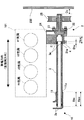
図2は図1の線X−Xに沿う冷却装置Aの断面図である。図2は、また、エンジン100を、車両の前部に形成したエンジンルーム内に配置したときの平面レイアウトを模式的に示している。エンジン100は、その気筒列方向が車幅方向と平行なるように配置されており、その気筒列方向の前部には、フロントサイドフレーム200が近接している。
FIG. 2 is a cross-sectional view of the cooling device A along the line XX in FIG. FIG. 2 also schematically shows a planar layout when the
ポンプユニット2は、戻り水路用配管3の一方端部が差し込まれるポンプ側差込孔21を備える。ポンプ側差込孔21は、その断面形状が円形であって、ポンプユニット2内の渦室22と連通している。渦室22内にはプーリ25に連結されたインペラ23が配置されている。渦室22には、ポンプユニット2内の吐出路24が連通しており、戻り水路用配管3から還流される冷却水は、インペラ23の回転により吐出路24からシリンダブロック101aへ圧送されることになる。
The
接続管部10は、戻り水路用配管3の他方端部が差し込まれる、断面形状が円形の出口部材側差込孔11を備える。戻り水路用配管3の両端部外周面には、それぞれ、溝が周設されており、これらの溝にそれぞれシール部材3a、3bが取り付けられている。シール部材3a、3bは、例えば、Oリングである。シール部材3aは、ポンプ側差込孔21の内周面と戻り水路用配管3の外周面との間に介在して、これらの間をシールする。また、シール部材3bは、出口部材側差込孔11の内周面と戻り水路用配管3の外周面との間に介在して、これらの間をシールする。
The connecting
このような構成により、戻り水路用配管3と、ポンプユニット2及び接続管部10との接続は、戻り水路用配管3の各端部を出口部材側差込孔11及びポンプ側差込孔21にそれぞれ差し込むだけで完了する。よって、組み付け作業が簡素化する。なお、本実施形態では、シール部材3a、3bを戻り水路用配管3に設けた構成としたが、ポンプ側差込孔21及び出口部材側差込孔11の各内周面に溝を周設することで、ポンプ側差込孔21及び出口部材側差込孔11に設ける構成としてもよい。
With such a configuration, the connection between the
次に、本実施形態の場合、出口部材側差込孔11及びポンプ側差込孔21は、いずれも、気筒列方向と平行な同一仮想直線をそれらの中心軸線としている。つまり、それらの深さ方向は同方向であり、気筒列方向と平行な方向である。
Next, in the case of this embodiment, the outlet member
出口部材側差込孔11は、気筒列方向前部へ向けて開口した開口端11aを有し、ポンプ側差込孔21は、気筒列方向後部へ向けて開口した開口端21aを有する。これらの開口端11a及び21aは互いに対向しており、気筒列方向の離間距離はDsである。
The outlet member
出口部材側差込孔11は深さDpoを有しており、ポンプ側差込孔21は深さDpwを有している。これらの深さDpo及びDpwいずれも、開口端11a及び21aから、戻り水路用配管3を差込み可能な最深部までの長さである。
The outlet member
戻り水路用配管3は、気筒列方向の長さがLである。本実施形態の場合、戻り水路用配管3は直線状をなしているため、気筒列方向の長さLは全長である。差込量Dioは、戻り水路用配管3の端部の出口部材側差込孔11に対する差込量を、差込量Diwは、戻り水路用配管3の端部のポンプ側差込孔21に対する差込量を、それぞれ示しており、開口端11a及び21aから、戻り水路用配管3の端面までの長さである。
The
通常時(エンジン100を使用しているとき)の差込量Dio及びDiwは、出口部材側差込孔11及びポンプ側差込孔21によって、戻り水路用配管3を支持するために必要な長さとする。図2は、通常時の差込状態を示しており、本実施形態の場合、ポンプ側差込孔21に対しては、戻り水路用配管3の端部は、ポンプ側差込孔21の最深部まで差し込まれている。一方、戻り水路用配管3の端部は、出口部材側差込孔11に対しては出口部材側差込孔11の最深部まで差し込まれた状態ではなく、更に差し込む余裕(深さDpo−差込量Diw)がある。
The insertion amounts Dio and Diw at the normal time (when the
さて、図2の状態からポンプユニット2をエンジン100から取り外す場合、ボルト4(図1参照)を取り外すことで、シリンダブロック101aからは取り外せるが、戻り水路用配管3の端部が未だ差し込まれた状態にあり、戻り水路用配管3から分離するためには、ポンプユニット2を気筒列方向前方に差込量Diwだけ移動しなければならない。
Now, when the
しかし、ポンプユニット2の気筒列方向前方には、フロントサイドフレーム200が位置しており、ポンプユニット2との気筒列方向の離間距離はDc(<差込量Diw)であり、干渉する。
However, the
本実施形態では、上記の通り、図2の通常時において、戻り水路用配管3の端部は、出口部材側差込孔11に対しては出口部材側差込孔11の最深部まで差し込まれた状態ではなく、更に差し込む余裕(深さDpo−差込量Diw)がある。よって、この分だけ、戻り水路用配管3を出口部材側差込孔11に更に差し込んでシフトすることで、ポンプユニット2を戻り水路用配管3から分離するための移動量を小さくできる。つまり、出口部材側差込孔11の深さDpoは、ポンプユニット2をエンジン本体から取り外す際、戻り水路用配管3を出口部材側差込孔11側へシフト可能なように、通常時の戻り水路用配管3の端部の差込量Dioよりも長い深さが設定されている。
In the present embodiment, as described above, the end of the
図3は、戻り水路用配管3を図2に示す通常の位置から出口部材側差込孔11側にシフトした態様を示す図であり、特に、戻り水路用配管3の端部を出口部材側差込孔11の最深部まで差し込んだ状態を示す。図3の態様では、戻り水路用配管3をシフトした分だけ差込量Diwが小さくなっており、離間距離Dcが差込量Diwよりも大きくなっている。したがって、ポンプユニット2をフロントサイドフレーム200と干渉せずに取り外すことができる。
FIG. 3 is a view showing a mode in which the
このように本実施形態では、取り外しに必要なポンプユニット2の移動量が小さくなるため、ポンプユニット2周辺のスペースを左程広くしなくても、ポンプユニット2のみをエンジン100から取り外すことができる。図2及び図3のレイアウトにおいては、エンジン本体101の気筒列方向前部がフロントサイドフレーム200に近接したレイアウトを採用しながら、ポンプユニット2のみをエンジン100から取り外すことができる。
As described above, in this embodiment, since the amount of movement of the
ここで、ポンプユニット2をフロントサイドフレーム200と干渉せずに取り外すための要件は、Dpo>L−Dc−Dsである。この寸法関係を満たすことで、フロントサイドフレーム200と干渉することなく、ポンプユニット2のみをエンジン100から取り外すことができる。なお、本実施形態では、ポンプユニット2の取り外し時にポンプユニット2と干渉する車両構成要素の例としてフロントサイドフレーム200を挙げたが、これに限られず、ポンプユニット2の取り外しの際に干渉し得る他の車両構成要素との関係で、上記寸法関係を設定することができることは言うまでも無い。
Here, the requirement for removing the
次に、戻り水路用配管3を通常の位置から出口部材側差込孔11側にシフトした場合、戻り水路用配管3がポンプ側差込孔21から抜け出るように深さDpoを設定してもよい。この場合、取り外しに必要なポンプユニット2の気筒列方向の移動量が0になる。しかし、そうすると、戻り水路用配管3が不用意にポンプユニット2から抜け落ちることも懸念される。したがって、図3に示すように、戻り水路用配管3の端部を出口部材側差込孔11の最深部まで差し込んだ場合に、ポンプ側差込孔21に対して、戻り水路用配管3の端部が差し込まれた状態であることが望ましい。そのために必要な寸法関係は、Dpo<L−Dsである。この場合、ポンプ側差込孔21と戻り水路用配管3との間で、シール部材3aによるシールが機能している方が望ましいことから、戻り水路用配管3の端面からシール部材3aまでの長さ(シール部材3aの幅を含む)をDとすると、寸法関係はDpo<L−Ds−Dであることが望ましい。
Next, when the
本実施形態では、ポンプユニット2及び戻り水路用配管3をエンジン本体101の排気側の側部に設けたが吸気側の側部に設けてもよい。尤も、本実施形態では、戻り水路用配管3が金属製であることにより、排気熱による戻り水路用配管3の劣化等の心配の無い配管構造をエンジン本体101の排気側に構築できる。また、排気マニホールド102の下方を戻り水路用配管3が通過する構成としたことにより、排気マニホールド102との干渉を避けて戻り水路用配管3を配置できる。
In the present embodiment, the
<第2実施形態>
上記第1実施形態では、戻り水路用配管3として直線状のものを利用したが、途中で曲折したものであってもよい。また、出口部材側差込孔11及びポンプ側差込孔21の各深さ方向が同方向でかつ気筒列方向と平行な方向としたが、これらは同方向でなくてもよく、平行であれば足り、また、気筒列方向と平行でなくてもよい。
<Second Embodiment>
In the said 1st Embodiment, although the linear thing was utilized as the
図4は、本発明の他の実施形態に係る冷却装置Bを適用したエンジン100の排気側の側部を示す図である。上記第1実施形態と同様の構成については同じ符号を付して説明を割愛し、異なる構成についてのみ説明する。
FIG. 4 is a diagram showing an exhaust-side side portion of
本実施形態の場合、戻り水路用配管3に代わる戻り水路用配管3'は途中で曲折した円筒状の金属管である。図4において、深さ方向d1は、ポンプユニット2に代わるポンプユニット2'の差込孔の深さ方向を示し、開口端21a'はポンプユニット2'の差込孔の開口端である。また、深さ方向d2は、接続管部10に代わる接続管部10'の差込孔の深さ方向を示し、開口端11a'は接続管部10'の差込孔の開口端である。深さ方向d1と深さ方向d2は互いに平行であるが、同方向ではない(同一直線上にない)。
In the case of the present embodiment, the
このような構成においても、深さ方向d1の方向(換言すれば、深さ方向d2の方向)に戻り水路用配管3'をシフトすることで、ポンプユニット2'を取り外す際、戻り水路用配管3'と分離するための深さ方向d1の方向の移動量を無くす、或いは、小さくできる。よって、ポンプユニット2'の深さ方向d1の方向の前方に位置する車両構成要素との干渉を回避して、ポンプユニット2'のみをエンジン100から取り外すことができる。
Even in such a configuration, when the
なお、この実施形態の場合、上記の寸法関係において、図4に示す通り、戻り水路用配管3の長さLは、深さ方向d1(つまり、深さ方向d2の方向)の長さであり、その全長ではない。また、開口端11a'及び21a'間の離間距離Dsも深さ方向d1(換言すれば、深さ方向d2の方向)の離間距離である。
In the case of this embodiment, in the above dimensional relationship, as shown in FIG. 4, the length L of the
A 冷却装置
1 冷却水出口部材
2 ポンプユニット
3 戻り水路用配管
3a、3b シール部材
11 出口部材側差込孔
11a 開口端
21 ポンプ側差込孔
21a 開口端
100 エンジン
101 エンジン本体
A Cooling device 1 Cooling
Claims (5)
前記エンジン本体の気筒列方向の後部に設けられ、前記エンジン本体内を流通した冷却水が排出される冷却水出口部材と、
前記冷却水出口部材と前記ポンプユニットとを接続し、前記冷却水出口部材から前記ポンプユニットへ前記冷却水を還流させる金属製の戻り水路用配管と、
前記ポンプユニットに設けられ、前記戻り水路用配管の一方端部が差し込まれるポンプ側差込孔と、
前記冷却水出口部材に設けられ、前記戻り水路用配管の他方端部が差し込まれる出口部材側差込孔と、
前記ポンプ側差込孔の内周面と前記前記戻り水路用配管の前記一方端部の外周面との間に介在する第1シール部材と、
前記出口部材側差込孔の内周面と前記前記戻り水路用配管の前記他方端部の外周面との間に介在する第2シール部材と、
を備えたエンジンの冷却装置において、
前記ポンプ側差込孔は、
前記エンジン本体の前記気筒列方向後部へ向けて開口した開口端を有すると共に、その深さ方向が所定方向であり、
前記出口部材側差込孔は、
前記エンジン本体の前記気筒列方向前部へ向けて開口した開口端を有すると共に、その深さ方向が、前記所定方向と同一又は平行であり、
前記出口部材側差込孔が、
前記ポンプユニットを前記エンジン本体から取り外す際、前記戻り水路用配管を前記出口部材側差込孔側へシフト可能なように、通常時の前記戻り水路用配管の前記他方端部の差込量よりも長い深さを有することを特徴とするエンジンの冷却装置。 A pump unit that is attached to one side of the front part in the cylinder row direction of the engine body having a plurality of cylinders arranged in a row, and pumps cooling water to the engine body;
A cooling water outlet member provided at a rear portion in the cylinder row direction of the engine body and from which the cooling water flowing through the engine body is discharged;
A metal return pipe for connecting the cooling water outlet member and the pump unit, and returning the cooling water from the cooling water outlet member to the pump unit;
A pump-side insertion hole provided in the pump unit, into which one end of the return water pipe is inserted;
An outlet member side insertion hole provided in the cooling water outlet member, into which the other end of the return water pipe is inserted;
A first seal member interposed between an inner peripheral surface of the pump-side insertion hole and an outer peripheral surface of the one end of the return water pipe;
A second seal member interposed between an inner peripheral surface of the outlet member side insertion hole and an outer peripheral surface of the other end of the return water pipe;
In the engine cooling device with
The pump side insertion hole is
The engine body has an opening end that opens toward the rear of the cylinder row direction of the engine body, and the depth direction is a predetermined direction,
The outlet member side insertion hole is
And having an opening end that opens toward the front of the cylinder row direction of the engine body, and the depth direction thereof is the same as or parallel to the predetermined direction,
The outlet member side insertion hole is
When the pump unit is removed from the engine main body, the return water channel pipe can be shifted to the outlet member side insertion hole side from the insertion amount at the other end of the return water channel pipe at normal time. An engine cooling device characterized by having a long depth.
前記ポンプ側差込孔及び前記出口部材側差込孔の各開口端間の前記所定方向の離間距離をDs、
前記出口部材側差込孔の深さをDpo、
前記エンジンの車両搭載時において、前記ポンプユニットに対して前記所定方向の前方に位置する車両構成要素と前記ポンプユニットとの前記所定方向の離間距離をDc、
とすると、
Dpo>L−Dc−Ds
であることを特徴とする請求項1に記載のエンジンの冷却装置。 The length in the predetermined direction of the return water pipe is L,
The distance in the predetermined direction between the opening ends of the pump side insertion hole and the outlet member side insertion hole is Ds,
The depth of the outlet member side insertion hole is Dpo,
When the engine is mounted on a vehicle, the distance in the predetermined direction between the vehicle component and the pump unit located in front of the predetermined direction with respect to the pump unit is Dc,
Then,
Dpo> L-Dc-Ds
The engine cooling device according to claim 1, wherein
前記エンジンが横置きで前記車両に搭載され、
前記車両構成要素がフロントサイドフレームであることを特徴とする請求項2に記載のエンジンの冷却装置。 The predetermined direction is a direction parallel to the cylinder row direction;
The engine is mounted horizontally on the vehicle;
The engine cooling device according to claim 2, wherein the vehicle component is a front side frame.
前記戻り水路用配管が、前記エンジンの排気マニホールドの下方に配設されていることを特徴とする請求項1乃至4のいずれか一項に記載のエンジンの冷却装置。 The pump unit is attached to an exhaust side of the engine body;
The engine cooling device according to any one of claims 1 to 4, wherein the return water pipe is disposed below an exhaust manifold of the engine.
Priority Applications (1)
| Application Number | Priority Date | Filing Date | Title |
|---|---|---|---|
| JP2008246539A JP2010077883A (en) | 2008-09-25 | 2008-09-25 | Cooling equipment for engine |
Applications Claiming Priority (1)
| Application Number | Priority Date | Filing Date | Title |
|---|---|---|---|
| JP2008246539A JP2010077883A (en) | 2008-09-25 | 2008-09-25 | Cooling equipment for engine |
Publications (1)
| Publication Number | Publication Date |
|---|---|
| JP2010077883A true JP2010077883A (en) | 2010-04-08 |
Family
ID=42208592
Family Applications (1)
| Application Number | Title | Priority Date | Filing Date |
|---|---|---|---|
| JP2008246539A Withdrawn JP2010077883A (en) | 2008-09-25 | 2008-09-25 | Cooling equipment for engine |
Country Status (1)
| Country | Link |
|---|---|
| JP (1) | JP2010077883A (en) |
Cited By (2)
| Publication number | Priority date | Publication date | Assignee | Title |
|---|---|---|---|---|
| JP2015143493A (en) * | 2014-01-31 | 2015-08-06 | ダイハツ工業株式会社 | Pump unit of internal combustion engine |
| JP2021085360A (en) * | 2019-11-27 | 2021-06-03 | スズキ株式会社 | Cooling device for engine |
-
2008
- 2008-09-25 JP JP2008246539A patent/JP2010077883A/en not_active Withdrawn
Cited By (3)
| Publication number | Priority date | Publication date | Assignee | Title |
|---|---|---|---|---|
| JP2015143493A (en) * | 2014-01-31 | 2015-08-06 | ダイハツ工業株式会社 | Pump unit of internal combustion engine |
| JP2021085360A (en) * | 2019-11-27 | 2021-06-03 | スズキ株式会社 | Cooling device for engine |
| JP7338431B2 (en) | 2019-11-27 | 2023-09-05 | スズキ株式会社 | engine cooling system |
Similar Documents
| Publication | Publication Date | Title |
|---|---|---|
| JP7088359B2 (en) | EGR device for internal combustion engine | |
| US6890228B2 (en) | Outboard motor equipped with water-cooled engine | |
| JP6284356B2 (en) | Internal combustion engine | |
| JP2009536287A (en) | Oil module with integrated cooling water path | |
| JP6174348B2 (en) | Internal combustion engine for vehicles | |
| JP2010265861A (en) | Fluid passage structure of internal combustion engine | |
| JP2013124592A (en) | Outboard motor and watercraft including the same | |
| JP2013124594A (en) | Outboard motor and watercraft including the same | |
| JP5146024B2 (en) | Cooling system | |
| US7481186B2 (en) | Engine with cooling water passage formed inside crank case | |
| US6976892B2 (en) | Water-cooled vertical engine, outboard motor equipped with water-cooled vertical engine, and outboard motor | |
| US6921306B2 (en) | Water-cooled vertical engine and outboard motor equipped therewith | |
| JP2010077883A (en) | Cooling equipment for engine | |
| JP2009108704A (en) | Engine cooling system | |
| US6976893B2 (en) | Water-cooled vertical engine and outboard motor equipped therewith | |
| JP5806072B2 (en) | Engine oil jet structure | |
| JP2008075631A (en) | Multi-cylinder engine | |
| JP2010084581A (en) | Structure for cooling egr gas | |
| US7056170B2 (en) | Water-cooled vertical engine and outboard motor equipped therewith | |
| US6913500B2 (en) | Outboard motor | |
| JP6606168B2 (en) | Water cooling engine | |
| JP6900806B2 (en) | Engine cooling system | |
| WO2014050723A1 (en) | Engine | |
| JP2022155125A (en) | Fluid cooling device for engine | |
| EP2806135B1 (en) | Cooling apparatus for internal combustion engine and motorcycle including same |
Legal Events
| Date | Code | Title | Description |
|---|---|---|---|
| RD03 | Notification of appointment of power of attorney |
Free format text: JAPANESE INTERMEDIATE CODE: A7423 Effective date: 20101001 |
|
| RD04 | Notification of resignation of power of attorney |
Free format text: JAPANESE INTERMEDIATE CODE: A7424 Effective date: 20101001 |
|
| A300 | Withdrawal of application because of no request for examination |
Free format text: JAPANESE INTERMEDIATE CODE: A300 Effective date: 20111206 |