JP2010142525A - Mount structure of bed plate - Google Patents
Mount structure of bed plate Download PDFInfo
- Publication number
- JP2010142525A JP2010142525A JP2008324904A JP2008324904A JP2010142525A JP 2010142525 A JP2010142525 A JP 2010142525A JP 2008324904 A JP2008324904 A JP 2008324904A JP 2008324904 A JP2008324904 A JP 2008324904A JP 2010142525 A JP2010142525 A JP 2010142525A
- Authority
- JP
- Japan
- Prior art keywords
- base plate
- rail
- locking
- mounting
- hole
- Prior art date
- Legal status (The legal status is an assumption and is not a legal conclusion. Google has not performed a legal analysis and makes no representation as to the accuracy of the status listed.)
- Pending
Links
Images
Landscapes
- Assembled Shelves (AREA)
Abstract
【課題】省スペースで取り付け作業が行えると共に、台板やレールの加工が簡単である台板のレールへの取り付け構造を提供することを目的としている。
【解決手段】マウントアングルに取り付けられる取り付け部と、台板を支持するための支持部と断面略L字状に折曲形成されたレールの、支持部の後面側端部には切り欠き凹部と係止突起を、前面側端部には切り欠き凹部と係止爪を設けると共に、台板には、係止突起と係止爪とに対向する係止穴を形成したことを特徴とする。
【選択図】図1An object of the present invention is to provide a mounting structure for mounting a base plate to a rail, which can be mounted in a small space and can be easily processed.
A mounting portion that is attached to a mount angle, a support portion for supporting a base plate, and a rail that is bent to have a substantially L-shaped cross section, and a notch recessed portion at a rear surface side end portion of the support portion. The locking projection is provided with a notch recess and a locking claw at the front side end portion, and the base plate is formed with a locking hole facing the locking projection and the locking claw.
[Selection] Figure 1
Description
本発明は、ラックの前後に配置されたマウントアングルにレールを渡し、レールに機器を載置する台板を取り付け可能とする各種機器を収納するラックにおける、台板の取り付け構造に関するものである。 The present invention relates to a mounting structure for a base plate in a rack for storing various devices that allow rails to be mounted on mount angles arranged at the front and rear of the rack, and a base plate for mounting the devices on the rails.
通信機器等を収納するためのラックには、四隅に、機器をマウントしたり、機器を載置する台板を取り付けたりするための、マウントアングルが設けられる。ラックマウント型の機器は、そのままマウントアングルに固定し、台板を取り付ける場合には、前後のマウントアングルにL型レールを渡し、このL型レールに台板を支持させる。 Racks for storing communication devices and the like are provided with mount angles at four corners for mounting the devices and attaching base plates on which the devices are placed. The rack-mount type device is fixed to the mount angle as it is, and when the base plate is attached, the L-type rail is passed to the front and rear mount angles, and the base plate is supported on the L-type rail.
L型レールは、マウントアングルへの固定部と、台板を支持させる支持部とで構成され、固定部には固定穴が設けられる。支持部には後面側に差し込み穴が設けられ、台板には、差し込み穴に差し込み可能である差し込み突起を形成する。差し込み突起は、台板の後方左右両端に折曲形成し、先端は鈎状に係止部を設けていた。また、L型レールの支持部の前方端部は台板を固定するための固定部を折曲形成していた。固定部には固定穴を、台板には固定穴に対向する位置にねじ穴を設けていた。ラックの前面側から、台板を斜め上方から差し入れ、台板の差し込み突起をL型レールの差し込み穴へ差し込む。台板をL型レールの支持部に支持させるように置き、前面側から、ねじ穴と固定穴にねじを挿通し、締め付け、台板をL型レールに固定していた。
しかしながら、上記従来の台板のレールへの取り付け構造では、台板を斜め上方から差し入れるために、台板の取り付け位置の上下には相当のスペースが必要であった。また、台板に差し込み突起を形成するのに、細かい作業が必要となり、手間がかかっていた。L型レールには、台板を固定するための固定部を形成するのに、折曲加工をしており、製作が面倒であった。台板の固定は、最終的に前面からのねじ止めによりなされ、ねじ締め作業が必要であった。 However, in the conventional mounting structure of the base plate to the rail, a considerable space is required above and below the mounting position of the base plate in order to insert the base plate obliquely from above. In addition, fine work is required to form the insertion protrusion on the base plate, which takes time and effort. The L-shaped rail is bent to form a fixing portion for fixing the base plate, which is troublesome to manufacture. The base plate was finally fixed by screwing from the front, and a screw tightening operation was required.
そこで本発明は、省スペースで取り付け作業が行えると共に、台板やレールの加工が簡単である台板のレールへの取り付け構造を提供することを目的とし、その構造は、マウントアングルに取り付けられる取り付け部と、台板を支持するための支持部と断面略L字状に折曲形成されたレールの、支持部の後面側端部には切り欠き凹部と係止突起を、前面側端部には切り欠き凹部と係止爪を設けると共に、台板には、係止突起と係止爪とに対向する係止穴を形成したことを特徴とする。 Therefore, the present invention has an object to provide a mounting structure for mounting a base plate to a rail that can be mounted in a space-saving manner and is easy to process the base plate and the rail. And a support part for supporting the base plate and a rail bent in a substantially L-shaped cross section, a notch recess and a locking projection are provided at the rear side end part of the support part, and a front side end part is provided. Is provided with a notch recess and a locking claw, and a locking hole facing the locking projection and the locking claw is formed in the base plate.
本発明は、マウントアングルに取り付けられる取り付け部と、台板を支持するための支持部と断面略L字状に折曲形成されたレールの、支持部の後面側端部には切り欠き凹部と係止突起を、前面側端部には切り欠き凹部と係止爪を設けると共に、台板には、係止突起と係止爪とに対向する係止穴を形成したため、例えば、台板のレールへの係止爪の加工が容易になったり、レールの台板を固定するための固定部の形成が不要になったり、台板のレールへの取り付け構造を形成するための加工が容易になり、製作が簡単にできるようになる。また、従来前面側で台板をレールに固定していたねじは、レールをマウントアングルに固定するためのねじ止めにより台板もレールに固定されるので、不用となり、加工も簡単になると共に作業工数も減らすことができる。 The present invention provides a mounting portion attached to the mount angle, a support portion for supporting the base plate, and a rail formed by bending the rail into a substantially L-shaped cross section. The locking projection is provided with a notch recess and a locking claw at the front side end, and the base plate is formed with a locking hole facing the locking projection and the locking claw. It is easy to process the pawls on the rail, it is no longer necessary to form a fixing part to fix the base plate of the rail, and processing to form the mounting structure of the base plate to the rail is easy It becomes easy to make. In addition, the screws that previously fixed the base plate to the rail on the front side are also unnecessary because the base plate is also fixed to the rail by screwing to fix the rail to the mount angle. Man-hours can also be reduced.
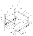
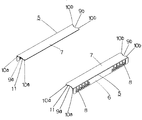
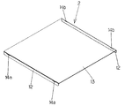
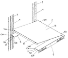
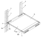
本発明に係る台板のレールへの取り付け構造を図1〜図5の添付図面に基いて説明する。 A structure for mounting a base plate to a rail according to the present invention will be described with reference to the accompanying drawings of FIGS.
各種通信機器等を収納するためのラック1において、四隅には、機器や機器を載置する台板2を固定するためのマウントアングル3を設ける。マウントアングル3には、取り付け穴4が設けられており、取り付け穴4を介して、直接機器を固定したり、機器を載置する台板2を支持するためのレール5を取り付けたりする。
In a rack 1 for storing various communication devices and the like,
台板2を支持するレール5は、断面略L字状に折曲し、取り付け部6と支持部7とを形成する。取り付け部6には、マウントアングル3の取り付け穴4に対向する固定穴8を形成する。支持部7の前後端部には、切り欠き凹部9a,9bを形成する。後面側端部の切り欠き凹部9bの両側には係止突起10bが形成される。一方、前面側端部切り欠き凹部9aの両側には係止突起10aを設けると共に、ラック1の内側に位置する係止突起10aには係止爪11を形成する。
The
台板2は前面側と後面側とに折曲部12を設け、断面略コ字状に形成する。台板2の前面と後面とそれぞれの折曲部12と台板部13との境界部分に、係止穴14a,14bを形成する。
The
前後のマウントアングル3にレール5を渡し、ねじ15により固定する。このとき、後面側は、ねじ15を締め付け本固定するが、前面側は、ねじ15を緩めに締めて仮固定とする。台板2をラック1の前面側から差し入れ、前面側より先にレール5の後面側に設けた係止突起10bに台板2の係止穴14bを引っ掛け、前面側へ引っ張りながら前面側の係止突起10aに係止穴14aを掛ける。係止爪11を係止穴14aに確実に係止させた後、仮止めであった前面側のねじ15を締め付けレール5をマウントアングル3に固定することで、係止爪11によってマウントアングル3から台板2が外れなくなり、台板2もレール5に固定される構造である。
The
従来の台板とレールの構造と比較する。台板は、後面側にはレールと係合させる差し込み突起が形成され、前面側をねじ止めすることでレールに固定していた。本発明の台板とレールは、まず、差し込み突起よりも単純な形状である切り欠きによって、係止される形状である。また、本発明に係る台板は、レールをマウントアングルに固定する作業によって同時にレールに固定される形状である。本発明の構造は、工程数も抑えることができ、形状も単純であるため、製造コストを引き下げることができる。また、作業数も減らすことができ、作業コストも抑えることができる。 Compared to the conventional base plate and rail structure. The base plate is formed with an insertion protrusion to be engaged with the rail on the rear side, and is fixed to the rail by screwing the front side. The base plate and the rail of the present invention have a shape that is locked by a notch that is simpler than the insertion protrusion. Moreover, the baseplate which concerns on this invention is a shape fixed to a rail simultaneously by the operation | work which fixes a rail to a mount angle. Since the structure of the present invention can reduce the number of steps and the shape is simple, the manufacturing cost can be reduced. In addition, the number of operations can be reduced and the operation cost can be reduced.
1 ラック
2 台板
3 マウントアングル
4 取り付け穴
5 レール
6 取り付け部
7 支持部
8 固定穴
9a 前面側端部切欠凹部
9b 後面側端部切欠凹部
10a 係止突起
10b 係止突起
11 係止爪
12 折曲部
13 台板部
14a 係止穴
14b 係止穴
15 ねじ
DESCRIPTION OF SYMBOLS 1
Claims (1)
Priority Applications (1)
| Application Number | Priority Date | Filing Date | Title |
|---|---|---|---|
| JP2008324904A JP2010142525A (en) | 2008-12-22 | 2008-12-22 | Mount structure of bed plate |
Applications Claiming Priority (1)
| Application Number | Priority Date | Filing Date | Title |
|---|---|---|---|
| JP2008324904A JP2010142525A (en) | 2008-12-22 | 2008-12-22 | Mount structure of bed plate |
Publications (1)
| Publication Number | Publication Date |
|---|---|
| JP2010142525A true JP2010142525A (en) | 2010-07-01 |
Family
ID=42563559
Family Applications (1)
| Application Number | Title | Priority Date | Filing Date |
|---|---|---|---|
| JP2008324904A Pending JP2010142525A (en) | 2008-12-22 | 2008-12-22 | Mount structure of bed plate |
Country Status (1)
| Country | Link |
|---|---|
| JP (1) | JP2010142525A (en) |
-
2008
- 2008-12-22 JP JP2008324904A patent/JP2010142525A/en active Pending
Similar Documents
| Publication | Publication Date | Title |
|---|---|---|
| JP2010000359A (en) | Guide rail holding device | |
| CN102340967A (en) | Stand column for cabinet frames | |
| TWI555485B (en) | Mounting bracket for a slide assembly | |
| JP2011104003A (en) | Article storage rack | |
| JP4958816B2 (en) | Toolless blank panel | |
| JP2014116462A (en) | Control device | |
| JP2003023278A (en) | Rack rail mounting structure | |
| CN106647955A (en) | Hard-disk support and hard-disk fixing device | |
| JP2013027675A (en) | Merchandise display shelf | |
| JP6322526B2 (en) | Cooling fan mounting structure | |
| JP2006280810A (en) | Display shelf apparatus | |
| JP2009099748A (en) | Mounting structure for mounting electrical equipment storage cabinet | |
| CN102841648A (en) | Expansion card holder | |
| JP4220915B2 (en) | System rack cabinet | |
| JP5030160B2 (en) | Front side structure of mounting rail | |
| JP3785481B2 (en) | Wall mounting device for shelf bracket mounting rail | |
| JP2010253068A (en) | Mirror mounting frame with storage shelf | |
| JP5757789B2 (en) | Wire rack mounting method and storage furniture | |
| JP5044460B2 (en) | Fixing member for wiring box | |
| JP5281613B2 (en) | Equipment storage cabinet | |
| JP2009106645A (en) | Mirror mounting structure | |
| JP2010067631A (en) | Case with fitting | |
| JP3655518B2 (en) | Optional member mounting structure | |
| JP2010278230A (en) | PCB holding structure | |
| JP2003324285A (en) | Housing holding structure |