JP2010142590A - Display system and display device - Google Patents
Display system and display device Download PDFInfo
- Publication number
- JP2010142590A JP2010142590A JP2008326175A JP2008326175A JP2010142590A JP 2010142590 A JP2010142590 A JP 2010142590A JP 2008326175 A JP2008326175 A JP 2008326175A JP 2008326175 A JP2008326175 A JP 2008326175A JP 2010142590 A JP2010142590 A JP 2010142590A
- Authority
- JP
- Japan
- Prior art keywords
- container
- rotation
- rotating
- protrusion
- display device
- Prior art date
- Legal status (The legal status is an assumption and is not a legal conclusion. Google has not performed a legal analysis and makes no representation as to the accuracy of the status listed.)
- Pending
Links
Images




Landscapes
- Details Of Rigid Or Semi-Rigid Containers (AREA)
Abstract
【課題】容器を陳列装置に縦置きに陳列する際に容器の標記をランダムな方向に向けて容
器を置いても、標記を所定の方向に向けて陳列することが可能な陳列システム等を提供す
る。
【解決手段】回転テーブル312に容器20が載せられると、回転テーブル312は下降
する。ここでベース板351にはねじ部が設けられ、またシャフト312cにもねじ部が
設けられている。このため、回転テーブル312は、回転しながら下降する。この結果、
回転テーブル312に載せられた容器20も回転しながら下降する。そして回転テーブル
312が下降すると、回転テーブル312の上面から第1突起352および第2突起35
3が突出する。そして、例えば突出した第1突起352が容器20の例えば第1凹部に入
り込む。これにより容器20の回転が停止されるとともに、例えば第2識別標記23bが
前方を向くようになる。
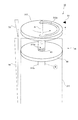
【選択図】図4An object of the present invention is to provide a display system capable of displaying a mark in a predetermined direction even when the container is placed in a random direction when the container is displayed vertically on a display device. To do.
When a container is placed on a rotary table, the rotary table is lowered. Here, the base plate 351 is provided with a screw portion, and the shaft 312c is also provided with a screw portion. For this reason, the rotary table 312 descends while rotating. As a result,
The container 20 placed on the rotary table 312 also descends while rotating. When the turntable 312 is lowered, the first protrusion 352 and the second protrusion 35 are formed from the upper surface of the turntable 312.
3 protrudes. For example, the protruding first protrusion 352 enters, for example, the first recess of the container 20. Thereby, the rotation of the container 20 is stopped and, for example, the second identification mark 23b is directed forward.
[Selection] Figure 4
Description
本発明は、容器の陳列を行う陳列システム等に関する。 The present invention relates to a display system for displaying containers.
例えばコンビニエンスストアなどにおいては、飲料缶やペットボトルなど飲料が充填さ
れた容器が、例えば陳列ケースに収容された陳列装置に縦置きに載せられて販売される。
そしてこのような陳列装置は、例えば、容器自身の自重により陳列ケースの前方に容器が
移動するように傾斜した状態で配置される。そして、手前側(最前列)の1つの容器を抜
き取ると、後続の容器が自重で手前側に移動する。
ここで陳列装置の容器が載せられる箇所には、容器の滑りの良さから例えばプラスチッ
クの平板が設けられる。また、近年では回転可能なローラを多数配置した陳列装置が出回
っている(例えば、特許文献1参照)。また、容器の補充は陳列装置の後方側から行うの
が一般的であるが、手前側からの容器の投入を可能とするとともに、奥側に移動した容器
が、再度手前側に移動し陳列される陳列装置も提案されている(例えば、特許文献2参照
)。即ち、前方側から投入された容器がUターンして戻ってくる陳列装置が提案されてい
る。さらに、容器に関するものとして、缶底に形成された環状凸部の内周壁に、内側凹部
と縦リブとが円周方向に交互に形成された缶が提案されている(例えば、特許文献3参照
)。
For example, in convenience stores and the like, containers filled with beverages such as beverage cans and plastic bottles are placed on a display device housed in a display case, for example, and placed on the market.
And such a display apparatus is arrange | positioned in the state inclined, for example so that a container might move ahead of a display case with dead weight of the container itself. When one container on the near side (front row) is extracted, the subsequent container moves to the near side by its own weight.
Here, a plastic flat plate, for example, is provided at a place where the container of the display device is placed because of the good sliding property of the container. In recent years, display devices in which a large number of rotatable rollers are arranged are on the market (for example, see Patent Document 1). In addition, the container is generally refilled from the rear side of the display device, but the container can be loaded from the front side, and the container moved to the back side is moved to the front side again and displayed. A display device has also been proposed (see, for example, Patent Document 2). That is, a display device has been proposed in which a container thrown in from the front side makes a U-turn and returns. Further, as a container, a can in which inner concave portions and vertical ribs are alternately formed in a circumferential direction on an inner peripheral wall of an annular convex portion formed on a can bottom has been proposed (see, for example, Patent Document 3). ).
ところで、容器の外面には、商品名や商標名など他の商品と識別するための標記が設け
られるが、この標記が購入者の取り出し方向に向いていないと、商品の識別がしにくくな
るとともに、商品の陳列時の見栄えが悪くなる。このため、陳列される容器は、例えば前
方側など、標記が所定の方向に向いていることが好ましい。
By the way, the outer surface of the container is provided with a mark for distinguishing it from other products such as a product name and a trade name, and it is difficult to identify the product if the mark is not suitable for the purchase direction of the purchaser. , The appearance at the time of display of the product becomes worse. For this reason, it is preferable that the container to be displayed is oriented in a predetermined direction such as the front side.
公報記載の従来技術として、容器が載せられる傾斜棚板の上面に、棚板傾斜方向に向け
て棒状のガイド凸条を設け、容器の底部に、標記の直下と標記が付された面とは反対側の
面の直下とを結ぶ凹状嵌合部を設け、このガイド凸条と凹状嵌合部とを用いて容器を陳列
する陳列方法が提案されている(例えば、特許文献4参照)。この陳列方法では、標記が
前方側を向く姿勢で凹状嵌合部をガイド凸条に嵌合させ、複数の容器を前後に並べる。こ
の結果、標記が前方を向いた状態で容器の陳列が行われる。
As the prior art described in the publication, on the top surface of the inclined shelf on which the container is placed, a bar-shaped guide ridge is provided in the inclination direction of the shelf, and the bottom of the container is directly below and the surface with the mark attached There has been proposed a display method in which a concave fitting portion is provided that connects directly below the opposite surface, and the container is displayed using the guide protrusion and the concave fitting portion (see, for example, Patent Document 4). In this display method, the concave fitting portion is fitted to the guide ridge in a posture in which the mark faces the front side, and a plurality of containers are arranged in the front-rear direction. As a result, the container is displayed with the mark facing forward.
上記特許文献4では、凹状嵌合部をガイド凸条に嵌合させ容器の陳列を行うことで、標
記を確実に前方に向けることが可能となる。しかしながら、かかる発明では、容器の投入
者は、容器を陳列装置に設置する度に凹状嵌合部をガイド凸条に嵌合させる必要があり、
容器の陳列作業が繁雑となる。また、標記が容器の一箇所にのみ形成されている場合には
、標記が後方側に向いた状態で陳列される陳列ミスの発生も懸念される。また、このコン
ビニエンスストアなどの多量の飲料を販売する店舗等では、向きを揃えて投入する作業が
非常に大掛かりとなる。
In Patent Document 4, the concave fitting portion is fitted to the guide ridge and the container is displayed, so that the mark can be reliably directed forward. However, in such an invention, the container supplier needs to fit the concave fitting portion to the guide ridge every time the container is installed in the display device.
Container display work becomes complicated. In addition, when the mark is formed only at one location of the container, there is a concern that a display error may occur in which the mark is displayed in the state of facing backward. In addition, in a store that sells a large amount of beverages such as this convenience store, the work of throwing in a uniform orientation becomes very large.
本発明は、容器を陳列装置に縦置きに陳列する際に容器の標記をランダムな方向に向け
て容器を置いても、標記を所定の方向に向けて陳列することが可能な陳列システム等を提
供することを主たる目的とする。
The present invention provides a display system that can display a mark in a predetermined direction even when the container is placed in a random direction when the container is displayed vertically on a display device. The main purpose is to provide.
かかる目的のもと、本発明が適用される陳列システムは、外面の特定箇所にて標記を行
なう容器と、容器を陳列する陳列装置と、を有し、陳列装置は、容器が載せられる載置部
と、載置部に載せられた容器を回転させる回転手段と、回転手段により回転された容器の
回転を停止させる回転停止部と、を備え、容器は、特定箇所が所定の方向を向く位置にて
回転が停止するように回転停止部と対峙する対峙部を備えたことを特徴とする。
For this purpose, a display system to which the present invention is applied has a container for marking at a specific location on the outer surface and a display device for displaying the container, and the display device is a mounting on which the container is placed. And a rotation means for rotating the container placed on the placement part, and a rotation stop part for stopping the rotation of the container rotated by the rotation means, and the container is a position where the specific portion faces a predetermined direction. And a counter part that opposes the rotation stop part so as to stop the rotation.
ここで、回転手段は、載置部の一部を回転させることにより容器を回転させることを特
徴とすることができる。また、回転手段は、容器の重みを利用して容器を回転させること
を特徴とすることができる。さらに、載置部には、容器の取り出し部に向けて複数の容器
を載置することが可能であり、回転手段が回転を行う容器と容器に隣接する他の容器とを
離間させる離間手段を更に備えることを特徴とすることができる。また、回転停止部は、
容器の最下端部と載置部との接触位置よりも容器側に突出する突起部であり、容器は、対
峙部として凹部又は凸部を有し、容器に設けられた凹部又は凸部が突起部に当接すること
で、特定箇所が所定の方向を向く位置にて容器の回転が停止されることを特徴とすること
ができる。
Here, the rotating means may be characterized in that the container is rotated by rotating a part of the mounting portion. The rotating means may be characterized by rotating the container using the weight of the container. Further, the mounting unit can be mounted with a plurality of containers toward the container take-out unit, and a separating unit that separates the container that the rotating unit rotates from another container adjacent to the container. Furthermore, it can be characterized by comprising. The rotation stop part
It is a protrusion that protrudes further toward the container than the contact position between the lowermost end of the container and the mounting part, and the container has a recess or a protrusion as an opposing part, and the recess or protrusion provided on the container protrudes By contacting the part, the rotation of the container can be stopped at a position where the specific portion faces a predetermined direction.
また、接触位置よりも容器側に突出した突起部は、容器に設けられた凹部又は凸部に当
接した後に非突出状態となることを特徴とすることができる。さらに、回転停止部は、磁
力を用いて容器の回転を停止させることを特徴とすることができる。また、載置部は、回
転可能に設けられ容器が載置される載置テーブルと、載置テーブルを容器が取り出される
取り出し部に向けて移動させる移動機構と、を備え、回転手段は、移動機構により取り出
し部に向けて移動する載置テーブルに抗力を付与し載置テーブルを回転させることで容器
を回転させ、回転停止部は、回転手段により回転する容器の対峙部と対峙することで、特
定箇所が所定の方向を向く位置にて容器の回転を停止させることを特徴とすることができ
る。また、本発明の陳列システムに使用される容器は、ICタグを装着した容器であることを特徴とすることができる。
Moreover, the protrusion part which protruded in the container side rather than the contact position can be set as the non-protrusion state after contact | abutting to the recessed part or convex part provided in the container. Further, the rotation stopping unit can stop the rotation of the container using magnetic force. The mounting unit includes a mounting table that is rotatably provided and on which the container is mounted, and a moving mechanism that moves the mounting table toward a take-out unit from which the container is taken out. The container is rotated by applying a drag force to the mounting table that moves toward the take-out unit by the mechanism and rotating the mounting table, and the rotation stopping unit is opposed to the counter part of the container that is rotated by the rotating means. It is possible to stop the rotation of the container at a position where the specific portion faces a predetermined direction. In addition, the container used in the display system of the present invention may be a container equipped with an IC tag.
また、本発明を陳列装置として捉えた場合、本発明が適用される陳列装置は、外面の特
定箇所にて標記を行なう容器を陳列する陳列装置であって、容器が載せられる載置部と、
載置部に載せられた容器を回転させる回転手段と、回転手段により回転された容器の回転
を停止させる回転停止部と、を備え、回転停止部は、容器の所定部位と対峙し、容器の特
定箇所が所定の方向を向く位置にて容器の回転を停止させることを特徴とする。また、本発明の陳列装置に使用される容器は、ICタグを装着した容器であることを特徴とすることができる。
Further, when the present invention is regarded as a display device, the display device to which the present invention is applied is a display device for displaying a container for marking at a specific place on the outer surface, and a placement unit on which the container is placed;
A rotation means for rotating the container placed on the placement section; and a rotation stop section for stopping the rotation of the container rotated by the rotation means. The rotation stop section faces a predetermined portion of the container, and The rotation of the container is stopped at a position where the specific portion faces a predetermined direction. Moreover, the container used for the display apparatus of this invention can be characterized by being a container equipped with an IC tag.
容器を陳列装置に縦置きに陳列する際に容器の標記をランダムな方向に向けて容器を置
いても、標記を所定の方向に向けて陳列することが可能な陳列システム等を提供すること
が可能となる。
To provide a display system or the like that can display a mark in a predetermined direction even when the container is placed in a random direction when the container is displayed vertically on a display device It becomes possible.
以下、添付図面を参照して、本発明を実施するための最良の形態について詳細に説明す
る。
図1は、本発明の実施形態に係る陳列装置の概略構成を示した図である。
同図(A)に示すように本実施形態における陳列装置30は、飲料が内部に充填された
容器20が載せられる載置部31と、容器20の移動経路(搬送経路)を形成するととも
に容器20の移動を案内するガイド32とを備えている。また、透明に形成されるととも
に載置部31の一側辺に沿って配置され、容器20の移動を停止させる規制板34を備え
ている。ここでガイド32は、例えば、その両端部が載置部31に形成された開口33に
差し込まれることにより載置部31に固定される。また、容器20には、円筒状の缶を例
示しているが所謂ペットボトルなどの樹脂製の容器やキャップを有した所謂ボトル缶など
も用いることができる。
The best mode for carrying out the present invention will be described below in detail with reference to the accompanying drawings.
FIG. 1 is a diagram showing a schematic configuration of a display device according to an embodiment of the present invention.
As shown in FIG. 1A, the
陳列装置30は、同図(B)に示すように、コンビニエンスストア、スーパーマーケッ
トなどに設置される陳列ケース10の内部に収納される。この陳列ケース10は、直方体
状に形成されたケース本体部10Aと、このケース本体部10Aに対して開閉可能に設け
られたドア10Bとにより主要部が構成されている。
ここで陳列装置30は、陳列ケース10に設けられた棚(不図示)の上に載せられる。
この際、陳列装置30は、規制板34が設けられた側がドア10B側に位置するように設
置される。また、規制板34が設けられた側が、規制板34が設けられた側とは反対側よ
りも下方に位置するように配置される。即ち、陳列装置30は、陳列ケース10の後方側
から容器20が取り出される前方側(取り出し部側)に向かって下り傾斜した状態で配置
される。
As shown in FIG. 2B, the
Here, the
At this time, the
ここで本実施形態における陳列ケース10は、後方側にもドアが設けられ(不図示)、
後方側も開放可能となっている。そしてこの後方側より陳列装置30に容器20が投入さ
れる。その後、この容器20は載置部31上をドア10B側に向かって移動する。即ち、
容器20を購入する購入者側に向かって移動する。なお、本明細書では、ドア10B側を
前方側(前方)と称しドア10Bとは反対側を後方側(後方)と称する場合がある。また
、陳列ケース10の幅方向(容器20が移動する方向に直交する方向)を横方向、幅方向
と称する場合がある。
Here, the
The rear side can also be opened. And the
It moves toward the purchaser who purchases the
陳列装置30についてより詳細に説明する。
図2は、陳列装置30の載置部31を説明する図である。ここで同図(A)は、陳列装
置30の前方側における上面図である。また、同図(B)は、陳列装置30の前方側にお
ける側面図である。
同図(A)に示すように、載置部31には、前方側の方が後方側よりも下方に位置する
ように配置され、即ち前方に向かって下り傾斜した状態で配置され、容器20が載せられ
る底板311が設けられている。なお底板311には、回転可能な円筒状のローラを複数
設けることができる。また底板311には、回転可能な球状のローラを複数設けてもよい
。また底板311には、例えばアクリル板など表面が平滑な板状部材を用いることもでき
る。
さらに載置部31には、底板311よりも前方に配置され、底板311から移動してき
た容器20が載せられる回転テーブル312が設けられている。この回転テーブル312
は、円盤状に形成され、また周方向への回転が可能となっている。このように本実施形態
は、載置部31の一部が回転可能な構成となっている。
The
FIG. 2 is a diagram illustrating the
As shown in FIG. 5A, the mounting
Further, the mounting
Is formed in a disc shape and can be rotated in the circumferential direction. As described above, in the present embodiment, a part of the
また、本実施形態における陳列装置30には、同図(B)に示すように、回転テーブル
312を介し容器20を回転させる回転機構35が設けられている。また、回転機構35
により回転する容器20と、この容器20に後続(隣接)する他の容器20とを離間させ
る離間機構36(離間手段の一例)が設けられている。
回転手段として機能する回転機構35は、回転テーブル312の下方に配置された円盤
状のベース板351と、ベース板351に取り付けられ且つ回転テーブル312とベース
板351との間に配置され、回転テーブル312を上方に付勢するコイルスプリング35
4とを備えている。なお、ベース板351には、ベース板351から上方に延びる円柱状
の第1突起352、第2突起353が設けられている。
In addition, the
A separation mechanism 36 (an example of a separation means) that separates the
The
4 is provided. The
回転テーブル312は、一方の側面側から他方の側面側にかけて貫通して設けられた第
1貫通孔312a、第2貫通孔312bを備えている(なお、本明細書では、回転テーブ
ル312に設けられたこのような貫通孔を単に「貫通孔312a」と称する場合がある)
。ここで第1貫通孔312aおよび第2貫通孔312bは、同図(A)に示すように、回
転テーブル312の周方向に沿って円弧状に形成されている。そして、本実施形態では、
第1貫通孔312a内に上記第1突起352が配置され、第2貫通孔312b内に上記第
2突起353が配置されている。
The rotary table 312 includes a first through
. Here, the first through
The
一方ベース板351は、その中央部に、一方の側面側から他方の側面側にかけて貫通し
て設けられた貫通孔351aを備えている。また、ベース板351は、貫通孔351aの
内周面に、螺旋状に形成されたねじ部351bを有している。
また回転テーブル312には、回転テーブル312の中央部から下方に延びるシャフト
312cが設けられている。そして、このシャフト312cの外周面には、螺旋状に形成
されたねじ部312dが設けられている。
ここで本実施形態では、ベース板351の貫通孔351aに、回転テーブル312のシ
ャフト312cが貫通配設されている。また、ベース板351と回転テーブル312は、
ベース板351のねじ部351bとシャフト312cのねじ部312dとが噛み合った状
態で配置されている。
On the other hand, the
The rotary table 312 is provided with a
Here, in the present embodiment, the
The
一方、離間機構36は、貫通配設されたピン361を中心とした回転(揺動)が可能な
棒状の回転部材362を備えている。この回転部材362は、一方の端部側が回転テーブ
ル312の下面に設けられた突起312eの下方に位置するように配置されている。また
、離間機構36は、上下方向に進退可能に設けられ、上方に移動した際に容器20の移動
経路上に突出(底板311の上面から突出)するとともに、下方へ移動した際にこの移動
経路から退避する進退部材363を備えている。そして、本実施形態では、この進退部材
363が上記回転部材362の上方に設けられるとともに、回転部材362の他方の端部
と進退部材363の下端部とが接触する構成となっている。
On the other hand, the
次いで容器20について説明する。
図3は、容器20を底部側から眺めた場合の図である。
本実施形態における容器20は、円筒状に形成され、また同図(A)に示すように、底
部21に、外方に向かった環状に突出した環状突出部211を備えている。また、環状突
出部211の内側の側面に、容器20の変形により形成された第1凹部212a、第2凹
部212bを備えている(なお本明細書においては、容器20に形成されるこのような凹
部を単に、凹部212と称する場合がある。)。ここで第1凹部212aおよび第2凹部
212bは互いに対向する関係で配置されている。付言すれば、第1凹部212aおよび
第2凹部212bは、容器20の周方向において、位相が180°ずれた状態で配置され
ている。
Next, the
FIG. 3 is a view when the
The
さらに容器20は、外面の一部である側部22の特定箇所に、商品名、商標名など他の
商品と識別するための第1識別標記23a、第2識別標記23bを有している(なお本明
細書においては、以下単に「識別標記23」と称する場合がある。)。ここで、第1識別
標記23aおよび第2識別標記23bは、同一の形態でもいいし異なる形態とすることも
できる。なお第1識別標記23aおよび第2識別標記23bは、容器20の周方向におい
て、位相が180°ずれた状態で配置されている。
Furthermore, the
なお、凹部212と識別標記23との関係を説明すると、容器20の周方向において、
第1識別標記23aと第1凹部212aは、位相が180°ずれた状態で配置されている
。また、第2識別標記23bと第2凹部212bも、位相が180°ずれた状態で配置さ
れている。付言すれば、第1識別標記23aと第1凹部212aは所定の位置関係を有し
て形成され、第2識別標記23bと第2凹部212bも所定の位置関係を有して形成され
ている。さらに説明すれば、第1識別標記23aと第1凹部212aは互いに異なる位置
に配置され、第2識別標記23bと第2凹部212bも互いに異なる位置に配置されてい
る。
The relationship between the
The
さらに説明すると、第1凹部212aは、第1識別標記23aが設けられている側とは
反対側に形成され、第2凹部212bは、第2識別標記23bが設けられている側とは反
対側に形成されている。また、本形態では、第1識別標記23aおよび第2識別標記23
bのように識別標記23が複数設けられるとともに、これらの識別標記の各々に対応して
凹部(第1凹部212a、第2凹部212b)が設けられている。
More specifically, the
A plurality of identification marks 23 are provided as in b, and recesses (
なお、本形態における識別標記23および凹部212は、これらのうち一方が形成され
た後に、この一方が形成された位置を基準として他方が形成される。
ここで、同図(A)では、缶として形成された容器20を例示したが、凹部212を形
成する態様は、ペットボトルなどの樹脂製の容器により適している。このような樹脂製の
容器では、金型に凹部212に対応した凸部を形成しておき、例えばブロア成形の過程で
凹部212を形成する。その後、識別標記23を有したフィルム(シール)を容器20に
巻く工程において位置合わせを行い、凹部212の形成位置を基準に識別標記23を有し
たフィルムを容器20に巻き付ける。
In addition, after the
Here, although the
他方、容器20がアルミニウム缶などである場合、凹部212の形成は次のように行わ
れる。例えば2ピースのアルミニウム缶の場合、カップ成形−DI(Draw&Iron
)成形−洗浄−外面印刷−乾燥−内面塗装−乾燥−口部縮径加工−検査、の順に加工等が
実施されるが、これらが実施される過程において凹部212を形成することができる。例
えば上記環状突出部211および凹部212は、例えばDI成形の工程にて形成すること
ができる。また、識別標記23は、外面印刷の工程にて位置合わせを行ったうえ、凹部2
12の形成位置を基準に、例えば多色オフセット印刷により形成することができる。
On the other hand, when the
) Molding, cleaning, outer surface printing, drying, inner surface coating, drying, mouth diameter reduction processing, and inspection are performed in this order, and the
For example, it can be formed by multi-color offset printing with reference to the 12 formation positions.
なお、多色オフセット印刷などを用いた外面印刷は、通常2000缶/分に迫る速度で
行われる。このため、凹部212を基準とした位置合わせが困難となる事態も想定される
。このため、例えば口部縮径加工よりも前の工程にて、容器20の回転を行うとともにセ
ンサ等を用いて例えば識別標記23の位置検出を行う。そして、この位置検出の結果を用
いて容器20を停止させた後に、金型等を用いて容器20に凹部212を形成することが
できる。なお、金型による凹部212の形成は、例えば特開2000−211624号公
報に開示された既存の技術を用いて行うことができる。また例えば、容器20の内部およ
び外部に金型を配し容器20の内外から圧力を加える成形機により形成することができる
。
Note that external printing using multicolor offset printing or the like is usually performed at a speed approaching 2000 cans / minute. For this reason, the situation where the alignment based on the
ここで、容器20における凹部212は、同図(B)に示すように、環状突出部211
の外側の側面に設けることもできる。
また、凹部212以外に、例えば同図(C)に示すように、環状突出部211の内側の
側面に、容器20の変形により形成された突出部213を設けることもできる。なおこの
ような形態は、ペットボトルなど成形加工の自由度の大きいものにより適している。
また、図示は省略するが、環状突出部211の外側の側面に突出部213を設けること
もできる。なお、突出部213や凹部212は、環状突出部211の側面に限られず、環
状突出部211により囲まれている領域や、環状突出部211と容器20の側部22(同
図(A)参照)との間における領域に形成してもよい。
Here, the
It can also be provided on the outer side surface.
In addition to the
Although not shown, the
また、上記では環状突出部211が設けられた容器20について説明したが、同図(D
)に示すように環状突出部211が設けられずほぼ平坦に形成された底部21に突出部2
13や凹部(不図示)を設けることもできる。なお本図は、いわゆる3ピース缶を例示し
ており、側部22とは別部材として構成された底部21が巻締めされた容器20を示して
いる。ここで突出部213や凹部(不図示)は、底部21に形成され、この底部21が側
部22に巻締めされることで容器20に付与される。
さらに突出部213は、例えば容器20の成形加工が難しい場合、容器20の変形によ
らず、同図(E)、(F)に示すように、樹脂片、金属片、接着剤、シート、シールなど
他の部材を取り付けることにより形成することもできる。なお、同図(E)は、突出部2
13を環状突出部211の内側に形成した例を示し、同図(F)は、突出部213を環状
突出部211の外側に形成した例を示している。
Moreover, although the
), The projecting portion 2 is formed on the
13 and a recessed part (not shown) can also be provided. In addition, this figure has illustrated what is called a three-piece can, and has shown the
Further, for example, when the molding process of the
13 shows an example in which the protruding
ここで例えば樹脂による突出部213の形成は、例えば、エポキシ系樹脂等に代表され
る熱可塑性の樹脂を溶融するとともに吐出する装置(例えば熱射ガン)を用い、容器20
に溶着することで行うことができる。また例えば、容器20の回転を行うとともにセンサ
等を用いて例えば識別標記23の位置検出を行う。そして、この位置検出の結果を用いて
容器20を停止させた後に、上記装置を用い所定位置に樹脂を付着(溶着)させる。これ
らの態様では、突出部213を速やかに形成でき、また工程が簡易なものとなる。なお、
容器20は販売時に加温等される場合がある。このため、突出部213に用いられる樹脂
は、加温販売時の温度では溶融しないものを選定することが好ましい。
Here, for example, the
It can be carried out by welding to. Further, for example, the
The
さらに、同図(G)、(H)に示すように、底部21に、例えば接着剤を塗布したり、
シールなど他の部材を貼付したりし、底部21から盛り上がる盛り上がり部214を設け
る。そして、この盛り上がり部214により相対的に凹んだ箇所を凹部212とすること
もできる。
Further, as shown in FIGS. (G) and (H), for example, an adhesive is applied to the
Another member such as a seal is attached, and a raised
なお、容器20の材質は、ビールなどのアルコール類、ジュースなどのソフトドリンク
類に使用可能なものであれば特に制限されない。例えば、アルミニウム、スチールなどの
金属、PET(ポリエチレンテレフタレート)などの樹脂、ガラスなどを用いることがで
きる。
また、容器20の形状や種類も特に限定されない。容器20には、例えば、いわゆるツ
ーピース缶(DI缶)、スリーピース缶、ペットボトル、ガラス瓶、ネジ付缶(いわゆる
ボトル缶)を挙げることができる。
The material of the
Further, the shape and type of the
ここで容器20にPET樹脂などの樹脂材料を用いる場合、ブロー成形などにより容器
20を形成する過程において、凹部212や突出部213を同時に形成することが好まし
い。このような場合、凹部212等の形成工程を別途設ける必要がないため、容器20の
製造工程を減らすことができる。またこの場合、例えば容器20からの突出部213の剥
離を防止することができる。なお容器20を形成した後に、突出部213を取り付けるこ
とも当然できる。
また容器20がいわゆるツーピース缶である場合、底部21を成形する工程で、同時に
凹部212や突出部213を形成することができる。付言すれば、ツーピース缶を形成す
る既知の工程のうち、底部21を形成する段階で併せて凹部212や突出部213を形成
することができる。なお、印刷工程が終了した後に、凹部212や突出部213を形成す
ることも当然可能である。
Here, when a resin material such as PET resin is used for the
Moreover, when the
なお、識別標記23の容器20への付与方法について更に説明すると、容器20が缶で
ある場合、上記のとおり例えば塗装、印刷により付与することができる。また、容器20
がペットボトル等である場合には、識別標記23を有するフィルムを上記のように容器2
0に巻き付けた後、このフィルムを熱収縮させることにより付与することができる。即ち
、識別標記23は、塗装などのみならずフィルム等を別途装着等することによっても付与
することができる。
ここで熱収縮させるフィルムの組成については、熱収縮フィルムとして通常使用される
組成とすることができる。例えば特開2006−341568号公報に記載されている組
成とすることができる。また、熱収縮させるフィルムの製造方法も特に限定されず、既存
の製造方法を採用することができる。例えば特開2006−341568号公報に記載さ
れている製造方法を採用することができる。また、フィルムを熱収縮させる条件も既存の
条件とすることができ、例えば90°のスチーム処理により熱収縮させることができる。
The method for applying the
Is a plastic bottle or the like, the film having the
After wrapping around 0, the film can be applied by heat shrinking. That is, the
Here, the composition of the film to be heat-shrinkable can be a composition usually used as a heat-shrinkable film. For example, it can be set as the composition described in Unexamined-Japanese-Patent No. 2006-341568. Moreover, the manufacturing method of the film to be heat shrunk is not particularly limited, and an existing manufacturing method can be adopted. For example, the manufacturing method described in JP-A-2006-341568 can be employed. Moreover, the conditions for heat shrinking the film can also be the existing conditions, and for example, the film can be heat shrunk by 90 ° steam treatment.
次いで本実施形態における陳列装置30および容器20の動作について図4を用いて説
明する。図4は、陳列装置30および容器20の動作を説明するための図である。
同図に示すように、回転テーブル312に容器20が載せられると、容器20の重みに
より、回転テーブル312は下降する。ところで本実施形態では、上記のように、ベース
板351にねじ部351b(図2参照)が設けられ、またシャフト312cにもねじ部3
12dが設けられている。このため、回転テーブル312は、例えば時計回りに回転しな
がら下降する。この結果、回転テーブル312に載せられた容器20も周方向且つ時計回
りに回転しながら下降する。
Next, operations of the
As shown in the figure, when the
12d is provided. For this reason, the rotary table 312 descends while rotating clockwise, for example. As a result, the
そして回転テーブル312が下降すると、回転テーブル312の上面から突起部として
機能する第1突起352および第2突起353が突出する。即ち載置される容器20の最
下端部と回転テーブル312との接触位置よりも容器20側に、第1突起352および第
2突起353が突出する。そして例えば、突出した第1突起352が容器20の例えば第
1凹部212a(図3(A)参照)に入り込み、第2突起353が容器20の第2凹部2
12bに入り込む。付言すれば、第1突起352が第1凹部212aと対峙し(当接し)
、第2突起353が第2凹部212bと対峙する(当接する)状態となる。これにより容
器20の回転が停止(規制)されるとともに、図4に示すように、例えば第2識別標記2
3bが前方を向くようになる。なお、本実施形態における第1突起352および第2突起
353は、容器20の回転を停止させる回転停止部として捉えることができる。また、第
1凹部212aおよび第2凹部212bは、回転停止部と対峙する対峙部として捉えるこ
とができる。ここで、本形態では第1凹部212aおよび第2凹部212bが設けられた
容器20を用いた例を説明したが、例えば突出部213が設けられた容器20(例えば図
3(E)参照)を用いた場合には、例えば第1突起352と突出部213とが突き当たり
、容器20の回転が停止される。
When the
Enter 12b. In other words, the
The
3b comes to face forward. In addition, the
なお、回転テーブル312上の容器20と後続する容器20とが接触していると、容器
20(回転テーブル312上の容器20)の回転が、後続する容器20に阻害されるおそ
れがある。このため、本実施形態では離間機構36を設けている。
If the
容器20の載置により回転テーブル312が下降する際、回転テーブル312における
突起312eも下降する。そしてこの突起312eは、回転部材362の一方の端部を押
圧する。これにより回転部材362の他方の端部が上昇するとともに、この他方の端部が
進退部材363を押圧し、進退部材363が容器20の移動経路上に突出する。付言すれ
ば進退部材363が底板311の上面(表面)から突出する。これにより、後続する容器
20の環状突出部211の外側面が進退部材363により押圧され、後続する容器20は
、陳列装置30の後方側へ移動する。この結果、同図に示すように回転テーブル312上
の容器20と後続する容器20とが離間する。
なお、回転テーブル312上の容器20が取り除かれると、回転テーブル312が上昇
するとともに、この上昇に連動して進退部材363が容器20の移動経路上から退避する
。そして底板311上の容器20(新たな容器20)が、回転テーブル312に移動する
。
When the rotary table 312 is lowered due to the placement of the
When the
本実施形態では、例えば第1識別標記23aが後方側を向いた状態で容器20が載置部
31に置かれたとしても、第1識別標記23aが前方に向くようになる。このため、容器
20を陳列装置30に投入する投入者が特別な操作をしないでも、例えば第1識別標記2
3aを前方に向けることが可能となる。
In the present embodiment, for example, even if the
3a can be directed forward.
ここで図5−1は、回転テーブル312および回転機構35の他の形態を示している。
図2で示した形態では、第1突起352および第2突起353のようにベース板351
から2つの突起が設けられるとともに、回転テーブル312に、これらの突起に対応した
2つの貫通孔(第1貫通孔312aおよび第2貫通孔312b)が設けられていた。その
一方で、図5−1(A)に示すように、1つの突起および1つの貫通孔(第1貫通孔31
2a)を設ける構成とすることもできる。
なお、上記のように2つの突起(第1突起352および第2突起353)を設けるとと
もに、容器20における識別標記23が1つである場合(容器20に識別標記23が一箇
所のみ設けられた場合)、識別標記23が後方を向いた状態で容器20の停止が行われる
おそれがある。このため、識別標記23が1つである容器20を用いる場合には、図5―
1に示したように、1つの突起(第1突起352)を設けるとともに、容器20に1つの
凹部212(本図では不図示)を設けることが好ましい。
また回転テーブル312上において容器20が一定位置に定まらない場合もある。この
ため、後述するように、規制板34を円弧状に形成し、容器20の位置がぶれないように
することも好ましい。特に識別標記23が1箇所のみ設けられた場合には、このような態
様がより有効となる。さらに、単純に突出部213を設けた容器20(図3(E)参照)
と円弧状の規制板34との組み合わせの方が、容器20の位置ずれに対してラフに対応で
き、容器20の停止ミスを減じることができる。
Here, FIG. 5A shows another embodiment of the rotary table 312 and the
In the form shown in FIG. 2, the
And two through holes (a first through
2a) may be provided.
As described above, two protrusions (the
As shown in FIG. 1, it is preferable to provide one protrusion (first protrusion 352) and one recess 212 (not shown in the drawing) in the
Further, the
And the arc-shaped
また、回転機構35は、同図(B)に示すような形態とすることもできる。なお、(B
1)は上面図を示し、(B2)は(B1)のA−A線における断面を示している。
本形態では、同図(B2)に示すように、ベース板351に、上方に向かって突出した
1つの突起355が設けられている。また、回転機構35は、回転テーブル312の上に
載置された(載せられた)載置部材356を備えている。
Further, the
1) shows a top view, and (B2) shows a cross section taken along line AA of (B1).
In this embodiment, as shown in FIG. 2B2, the
ここで載置部材356は、同図(B1)に示すように、略円盤状に形成されている。ま
た、載置部材356は、その中心部から外縁部に向かって形成され且つ載置部材356の
一方面側と他方面側とを結ぶスリット356aを備えている。また、載置部材356は、
回転テーブル312の上面を露出させる窓部356bを備えている。そして、本形態では
、スリット356aの内部に突起355が配置された構成となっている。なお同図(B)
では、図2で示したコイルスプリング354等の図示を省略している。
Here, the mounting
A
Then, illustration of the
次いで図5−2(回転機構35、容器20の動作を説明する図)を用いて、回転機構3
5および容器20の動作について説明する。なおここでは、図3(E)に示した容器20
を用いた場合の動作を一例として説明する。
回転テーブル312上に容器20が置かれると、容器20の重みにより、回転テーブル
312は回転しつつ下方へ移動する。より具体的には、回転テーブル312は、同図(A
1)の矢印に示すように、例えば反時計回りに回転を行う。またこの回転に応じて下降す
る。この際、容器20も、窓部356bを通じて接触する回転テーブル312から回転力
が付与され、反時計回りに回転する。
Next, referring to FIG. 5B (a diagram illustrating the operation of the
5 and the operation of the
An example of the operation when using is described.
When the
As indicated by the arrow 1), for example, the rotation is performed counterclockwise. Moreover, it descends according to this rotation. At this time, the
なお載置部材356は、容器20と同様に、回転テーブル312から回転力が付与され
るものの、スリット356a内に突起355が位置しているため、この突起355により
回転が規制される。このため、載置部材356は、回転テーブル312と共に下方へ移動
するものの回転は行わない。
そして、回転テーブル312および載置部材356が所定量を下降すると、同図(A3
)に示すように、突起355が載置部材356の上面から突出するようになる。そして、
同図(A2)に示すように、突起355と突出部213とが接触し(突き当たり)、容器
20の回転が停止される。この結果、図2等で示した態様と同様に、識別標記23が前方
を向くようになる。
As with the
Then, when the rotary table 312 and the mounting
), The
As shown in FIG. 2A2, the
なお上記実施形態では、第1突起352(図2参照)等を第1凹部212a(図3(A
)参照)等に入り込ませたり、突起355と突出部213とを接触させたりすることで容
器20の回転を停止させた。ところで回転する容器20の回転停止は、例えば磁力を用い
て行うこともできる。
例えば図6(陳列装置30の他の形態を説明する図)の(A1)に示すように、規制板
34の幅方向における中央部に磁石342(特にNd−Fe−B系磁石が小さく且つ強力
であるので好適である)を設けるとともに、(A2)に示すように、容器20の側部22
に磁石24(特にNd−Fe−B系磁石が小さく且つ強力であるので好適である)を設け
る。そして、回転テーブル312に載せられ回転する容器20の磁石24と、規制板34
に設けられた磁石342とを互いに引き合わせることで容器20の回転を停止させること
ができる。即ち、磁力を用いて容器20の回転停止を行うことができる。
なお上記では、載置部31側および容器20側に磁石を設ける例を説明したが、一方の
みに磁石を設け他方にはこの磁石により吸引される金属を設けることができる。また、金
属を用いる場合、金属片(例えば市販のSUS430の薄板片(例えば0.1mm厚))
を貼り付けることもできる。また、金属片に限られず、例えばFe系の磁性粉末が入れら
れた塗料などを塗布してもよい。この場合は、塗料の中の磁性粉末含有量をなるべく増や
すとともに、磁性粉末の絶対量が必要であるので塗料膜厚を大きくすることが好ましい。
なお、塗布が難しい場合は、磁性粉末を含有し且つフィルム状にした樹脂を貼り付けても
よい。
In the above embodiment, the first protrusion 352 (see FIG. 2) or the like is formed in the
))) Or the like, or the
For example, as shown in FIG. 6 (A1) in FIG. 6 (a diagram for explaining another form of the display device 30), a magnet 342 (especially an Nd—Fe—B magnet is small and strong in the center in the width direction of the regulating plate 34). And the
Is provided with a magnet 24 (especially suitable because an Nd-Fe-B magnet is small and strong). Then, the
The rotation of the
In addition, although the example which provides a magnet in the mounting
You can also paste. Moreover, it is not restricted to a metal piece, For example, you may apply | coat the coating material in which Fe type magnetic powder was put. In this case, it is preferable to increase the coating film thickness because the magnetic powder content in the coating is increased as much as possible and the absolute amount of the magnetic powder is required.
In addition, when application | coating is difficult, you may affix the resin which contains magnetic powder and was made into the film form.
また同図(B)に示すように、規制板34を、円弧状に形成するともに回転テーブル3
12の周縁に沿って配置することもできる。さらに、規制板34のうち容器20と接触す
る箇所に(規制板34の内周面に)、例えば球状(ベアリング状)の回転部材343を設
けることもできる。この場合、容器20の位置決めをより確実に行うことが出来るととも
に、容器20の回転をより円滑に行うことができる。なお、同図(B)では、2つの磁石
342を互いに対向する関係で配置している。また、本形態では球状の回転部材343を
例示したが、回転可能なローラ状の部材を設けることもできる。
Further, as shown in FIG. 5B, the restricting
It can also be arranged along 12 perimeters. Further, for example, a spherical (bearing-shaped) rotating
―第2の実施形態―
次に図7および図8を用いて第2の実施形態について説明する。なお、図7は、第2の
実施形態における陳列装置30を前方から眺めた場合の図であり、図8は、陳列装置30
および容器20の動作等を説明する図である。
上記第1の実施形態では、回転テーブル312が載置部31の前方側に配置され、底板
311が載置部31の後方側に配置されていた。一方、本実施形態では、図7に示すよう
に、回転テーブル312が載置部31の後方側に配置され、底板311が載置部31の前
方側に配置されている。
-Second Embodiment-
Next, a second embodiment will be described with reference to FIGS. 7 is a view of the
It is a figure explaining operation | movement of the
In the first embodiment, the rotary table 312 is disposed on the front side of the
なお底板311は、第1の実施形態と同様に、前方側が後方側よりも下方に位置するよ
うに配置され、即ち前方に向かって下り傾斜した状態で配置されている。また、回転テー
ブル312も、前方側が後方側よりも下方に位置するように配置され、即ち前方に向かっ
て下り傾斜した状態で配置されている。なお、図7の符号7A、7Bに示す三角形は、回
転テーブル312および底板311の傾斜の状態を示している。
As in the first embodiment, the
ここで本実施形態においても、図7に示すように、容器20を回転させる回転機構35
が設けられている。本実施形態における回転機構35は、上記第1の実施形態と同様に、
円盤状のベース板40を備える。また、回転テーブル312に設けられたシャフト312
cを回転駆動させるモータMと、回転テーブル312に容器20が置かれたことを検知す
る容器検知センサS1とを備えている。また、本実施形態では、ベース板40から上方に
向かって突出するとともに、回転テーブル312のおける貫通孔312aに貫通配設され
た棒状の突起41(突起部の他の一例)が設けられている。ここで突起41は、回転テー
ブル312の後方側に位置するとともに、その先端が回転テーブル312の上面より若干
突き出た状態となっている。なお突起41は、回転テーブル312が半回転するとともに
上昇した際に、回転テーブル312の上面から非突出状態となる。付言すれば、回転テー
ブル312が半回転した際に、突起41が回転テーブル312の上面から非突出状態とな
るように、貫通孔43の内周面に形成されたねじ部(後述)のピッチ、シャフト312c
のねじ部312dのピッチが設定されている。
Here, also in this embodiment, as shown in FIG. 7, a
Is provided. The
A disk-shaped
a motor M for rotating c, and a container detection sensor S1 for detecting that the
The pitch of the
さらに本実施形態における陳列装置30は、容器検知センサS1からの出力を受け付け
るとともにモータMを制御する制御部(不図示)を備えている。ここで制御部は、CPU
(Central Processing Unit)、ROM(Read Only Memory)、RAM(Random Access Memory
)(いずれも不図示)を備えている。そして制御部のCPUは、ROMに記憶されたプロ
グラムに従い、RAMとの間で適宜データのやりとりを行いながらモータMの駆動制御を
実行する。
なお本実施形態においても、第1の実施形態と同様に、ベース板40の貫通孔43に回
転テーブル312のシャフト312cが貫通配設されている。また、貫通孔43の内周面
に形成された螺旋状のねじ部(不図示)とシャフト312cのねじ部312dとが噛み合
った状態となっている。
Further, the
(Central Processing Unit), ROM (Read Only Memory), RAM (Random Access Memory)
) (Both not shown). Then, the CPU of the control unit executes drive control of the motor M while appropriately exchanging data with the RAM in accordance with a program stored in the ROM.
In the present embodiment, as in the first embodiment, the
ここで本実施形態の陳列装置30には、例えば図3(E)に示した容器20を用いるこ
とができる。即ち、図8(A)に示すように、環状突出部211の内側に突出部213(
凸部の一例)を形成した容器20を用いることができる。なお、図3(E)に示した容器
20に限られず、図3(A)等に示した容器20も当然ながら用いることができる。
次いで図8(B)を用い、回転テーブル312および容器20の動作について説明する
。
まず回転テーブル312に容器20が置かれ、容器20が容器検知センサS1にて検知
されると、制御部(不図示)がモータMを駆動する。これにより、回転テーブル312が
、同図(B1)に示すように反時計回りに回転しながら上昇する。また回転テーブル31
2の回転に伴い容器20も反時計回りに回転する。その後、同図(B2)に示すように、
容器20の突出部213と突起41とが当接し(対峙し)、容器20の回転が停止される
。なお、容器20の回転が停止された際、容器20は、同図(B2)に示すように、識別
標記23が前方を向く状態となる。ここで突起41は、容器20の回転を停止させる回転
停止部として捉えることができる。また突出部213は、突起41と対峙する対峙部とし
て捉えることができる。
Here, for example, the
A
Next, the operation of the rotary table 312 and the
First, the
With the rotation of 2, the
The
そして、回転テーブル312が更に上昇すると、突起41の先端が回転テーブル312
の上面よりも下方に位置する状態となる。即ち、突起41は、回転テーブル312に対し
非突出状態となる。この結果、突起41と環状突出部211との接触が解除され(突起4
1と環状突出部211とが非接触状態となり)容器20は前方への移動を開始する(同図
(B3)参照)。これにより容器20は、識別標記23が前方を向いた状態で、陳列装置
30の前部に陳列される。
When the
It will be in the state located below the upper surface. That is, the
1 and the
―第3の実施形態―
次に図9〜図11を用いて第3の実施形態について説明する。
ここで図9は、第3の実施形態における陳列装置30を示した図である。なお、同図(
A)は、陳列装置30の側面図を示し、同図(B)は、陳列装置30の上面図を示してい
る。また、図10は、本実施形態における陳列装置30に用いられる容器20を説明する
ための図である。また、図11は、陳列装置30および容器20の動作を説明するための
図である。
-Third embodiment-
Next, a third embodiment will be described with reference to FIGS.
FIG. 9 is a view showing the
A) shows a side view of the
図9に示すように、本実施形態における陳列装置30の載置部31は、無端状に形成さ
れ且つ循環移動が可能に構成されたベルト部材61、ベルト部材61の内側に配置されベ
ルト部材61を内側から張架する第1張架ロール62、第2張架ロール63を備えている
。また、載置部31は、ベルト部材61の表面側に取り付けられた第1テーブル66を複
数備えている。なお、この第1テーブル66は、ベルト部材61に対する回転ができない
状態で取り付けられている。ここでベルト部材61、第1張架ロール62、第2張架ロー
ル63は、後述する第2テーブル67を、容器20の取り出し部側である前方側に向けて
移動させる移動機構として捉えることができる。
As shown in FIG. 9, the
さらに、載置部31は、各第1テーブル66の上部に、第1テーブル66に対して相対
回転可能な第2テーブル67(載置テーブルの一例)を備えている。また、載置部31は
、各第1テーブル66に、上方(容器20が置かれる側)に向かって突出する磁石68(
回転停止部の他の一例)を備えている。さらに載置部31には、前後方向に沿って配置さ
れ且つ各第2テーブル67の側面に接触配置され、第2テーブル67に抗力を付与するこ
とで第2テーブル67を回転させる接触部材69が設けられている。
Furthermore, the
Another example of the rotation stop unit) is provided. Furthermore, a
一方、本実施形態における容器20は、図10に示すように、側部22に磁石24(対
峙部の他の一例)を備えている。また、容器20は、側部22に、識別標記23を有して
いる。ここで、磁石24と識別標記23は、容器20の周方向において位相が90°ずれ
た状態で配置されている。なお本実施形態では、陳列装置30側および容器20側に磁石
を設ける例を説明したが、一方のみを磁石とし他方をこの磁石により吸引される金属とす
ることができる。なお金属を用いる場合、金属片を貼付することもできるし例えばFe系
の材料を含有した塗料等を塗布等することもできる。また磁性粉末を含有した樹脂フィル
ムを貼付してもよい。
On the other hand, the
図11を用い陳列装置30および容器20の動作を説明する。
第2テーブル67に容器20が置かれると、容器20の重みが第2テーブル67および
第1テーブル66を介してベルト部材61に伝達され、ベルト部材61の循環移動が開始
される。これによって、容器20が置かれた第1テーブル66および第2テーブル67は
前方への移動を開始する。
なお、第2テーブル67の側面には、上記のとおり、接触部材69が接触配置されてい
る。このため、第2テーブル67の一方側に接触部材69から抗力が付与される状態とな
り、第2テーブル67は、前方への移動を行う際に時計回りに回転する。そして、第2テ
ーブル67が回転すると容器20も回転するようになる(符号13A参照)。ここで接触
部材69は、容器20を回転させる回転手段として捉えることができる。
Operation | movement of the
When the
As described above, the
そして、容器20の磁石24と第1テーブル66に設けられた磁石68とが互いに引き
合う状態(対峙する状態)となると、容器20の回転が停止される(符号13B参照)。
ここで容器20の回転が停止された際、容器20の識別標記23は前方を向く状態となる
。
なお、本実施形態は、容器20の磁石24と第1テーブル66に設けられた磁石68と
が互いに引き合う状態となると、付言すれば回転停止された容器20により第2テーブル
67の回転が規制されると、第2テーブル67と接触部材69との間でスリップが生じる
構成となっている。このため、回転停止した容器20は、以後回転することなく前方へ移
動していく。即ち、容器20は識別標記23が前方を向いた状態で前方へ移動していく。
Then, when the
Here, when the rotation of the
In this embodiment, when the
ここで図12は、図9に示した陳列装置30の変形例を示した図である。
図9に示した陳列装置30では、第1テーブル66の下方にベルト部材61が設けられ
、このベルト部材61に第1テーブル66が固定されていた。本変形例では、容器20の
移動経路の側方のそれぞれに、循環移動が可能なベルト部材が設けられている。即ち、循
環移動が可能なベルト部材が2つ設けられている。そして、この2つのベルト部材の両者
に第1テーブル66が取り付けられた状態となっている。
Here, FIG. 12 is a view showing a modification of the
In the
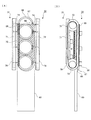
詳細に説明すると、本変形例では、図12(A)に示すように、容器20の移動経路の
一方の側方に第1ベルト部材71が設けられ、移動経路の他方の側方に第2ベルト部材7
2が設けられている。なお、第1ベルト部材71および第2ベルト部材72の両者は、無
端状に形成され循環移動が可能となっている。また、本変形例では、同図(B)に示すよ
うに、第1ベルト部材71の内側に配置されこの第1ベルト部材71を内側から張架する
2つの張架ロール73が設けられている。なお、図示は省略するが、第2ベルト部材72
の内側にも、第2ベルト部材72を張架する2つの張架ロールが設けられている。
More specifically, in this modification, as shown in FIG. 12A, the
2 is provided. Both the
Two tension rolls for tensioning the
さらに本変形例では、同図(A)に示すように、複数設けられた第1テーブル66の各
々を、第1ベルト部材71および第2ベルト部材72に接続する棒状の接続部材74が設
けられている。なお接続部材74は、接続部材74を通る直線を軸心とした第1テーブル
66の回転が可能なように、第1テーブル66と第1ベルト部材71等とを接続している
。また、本変形例では、同図(B)に示すように、容器20が第2テーブル67に載せら
れ第1テーブル66が下降した場合に、この下降した第1テーブル66を支持する支持板
75が設けられている。また、同図(A)に示すように、第1ベルト部材71および第2
ベルト部材72を覆うカバー部材76が設けられている。また、本変形例では、陳列装置
30の前方側に、第2テーブル67からの容器20が載せられるとともに、この容器20
を前方にスライドさせる傾斜板80が設けられている。ここでこの傾斜板80は、前方に
位置する第2テーブル67よりも下方に位置している。なお、傾斜板80には、表面が平
滑な例えばアクリル板を用いることもできるし、回転可能なロール状部材を複数配置して
もよい。
Further, in the present modification, as shown in FIG. 5A, rod-shaped
A
An
ここで本変形例の陳列装置30にて容器20が載せられた場合、上記と同様に動作を行
う。即ち、第2テーブル67に容器20が置かれると、容器20の重みが第2テーブル6
7、第1テーブル66、接続部材74を介して第1ベルト部材71および第2ベルト部材
72に伝達される。そして、第1ベルト部材71および第2ベルト部材72の循環移動が
開始される。これにより、容器20が置かれた第1テーブル66および第2テーブル67
は前方への移動を開始する。そして、第2テーブル67の回転が開始されるとともに容器
20の回転も開始される。その後、容器20の磁石24(図10参照)と第1テーブル6
6に設けられた磁石68とが互いに引き合う状態(対峙する状態)となると、容器20の
回転が停止される。そして容器20の回転が停止された際、容器20の識別標記23(図
10参照)が前方を向く状態となる。その後、第1ベルト部材71等が前方側の張架ロー
ル73に巻き付くように下方へ移動すると、この第1ベルト部材71の移動に対応し、第
2テーブル67が傾斜状態となる。詳細には、前方側が後方側よりも下方に位置するよう
に傾斜状態となる。これにより容器20は、第2テーブル67から滑り落ち、傾斜板80
に載るようになる。そして、この容器20は、傾斜板80を前方に向かって移動していく
。
Here, when the
7, and transmitted to the
Starts moving forward. Then, the rotation of the second table 67 is started and the rotation of the
When the
It comes to be put on. And this
なお、本変形例では、第1テーブル66、第2テーブル67、および磁石68の重量バ
ランスが調整され、常に、第2テーブル67よりも第1テーブル66が下方に位置するよ
うになっている。このため、容器20の載置が終了し第1テーブル66等が後方側へ戻る
際には、上記のように第2テーブル67等が傾斜状態となるものの、第2テーブル67よ
りも第1テーブル66が下方に位置するようになる。この結果、磁石68が陳列装置30
の下方側に突出しない状態、付言すれば、磁石68が上方側に突出する状態となる。そし
てこの場合、陳列装置30の高さ方向(厚み方向)の寸法が、図9で示した態様よりも小
さくなる。
In this modification, the weight balance of the first table 66, the second table 67, and the
In other words, the
在庫あるいは、販売の数量を含めた商品管理に最近ICタグが使用されているが、本発明の容器20にこれを組み込み、陳列システムの中の付加機能の一つとして利用できる。例えば、本システムを使用する装置、容器を用いれば容器の取出し口において、標記23に対応する位置に容器方向を向かせることができるので、ICタグの位置を標記と一定関係の位置に置けば近接した陳列装置の位置にリーダ・ライタを置くことができる。これにより、顧客の出し入れのリアルタイムでの動きを把握することができる。
Recently, an IC tag has been used for merchandise management including inventory or sales quantity, but it can be incorporated into the
ICタグは、例えばペットボトルのような場合は、フィルムのような包装体に事前に接着したものを容器20の側面に巻き付け、あるいはキャップ内部に挿入することが出来る。また、缶のような容器では、側面に貼付したり、タブ部分に埋め込む等の方法にていずれも各容器一個ごとに装着することができる。
リーダ・ライタは、取出し口付近の一定位置に置けば、本システムを使用した場合、ほぼ定位置に容器20の標記23が向くので標記と一定関係部分にICタグを設置することで、リーダ・ライタを固定設定することができオンラインで容器の動きが手作業をすることなく把握できる。
For example, in the case of a PET bottle, the IC tag can be wrapped around a side surface of the
If the reader / writer is placed at a fixed position near the outlet, when the system is used, the
リーダ・ライタからのデータ情報は、ホストコンピューターにて一括処理・管理され販売・在庫等の管理データとして活用される。 Data information from the reader / writer is collectively processed and managed by the host computer and used as management data for sales and inventory.
20…容器、24…磁石、30…陳列装置、31…載置部、35…回転機構、36…離間
機構、41…突起、61…ベルト部材、62…第1張架ロール、63…第2張架ロール、
67…第2テーブル、68…磁石、69…接触部材、212a…第1凹部、212b…第
2凹部、213…突出部、352…第1突起、353…第2突起
DESCRIPTION OF
67 ... second table, 68 ... magnet, 69 ... contact member, 212a ... first recess, 212b ... second recess, 213 ... projection, 352 ... first projection, 353 ... second projection
Claims (11)
前記容器を陳列する陳列装置と、
を有し、
前記陳列装置は、
前記容器が載せられる載置部と、
前記載置部に載せられた容器を回転させる回転手段と、
前記回転手段により回転された前記容器の回転を停止させる回転停止部と、を備え、
前記容器は、
前記特定箇所が所定の方向を向く位置にて回転が停止するように前記回転停止部と対峙
する対峙部を備えたこと
を特徴とする陳列システム。 A container for marking at a specific location on the outer surface;
A display device for displaying the container;
Have
The display device includes:
A placement section on which the container is placed;
Rotating means for rotating the container placed on the mounting portion,
A rotation stop portion for stopping rotation of the container rotated by the rotation means,
The container is
A display system, comprising: a confronting portion that confronts the rotation stopping portion so that the rotation stops at a position where the specific portion faces a predetermined direction.
を特徴とする請求項1記載の陳列システム。 The display system according to claim 1, wherein the rotating unit rotates the container by rotating a part of the mounting portion.
求項1又は2記載の陳列システム。 The display system according to claim 1, wherein the rotating unit rotates the container using the weight of the container.
であり、
前記回転手段が回転を行う前記容器と当該容器に隣接する他の容器とを離間させる離間
手段を更に備えることを特徴とする請求項1乃至3のいずれかに記載の陳列システム。 It is possible to place a plurality of the containers toward the take-out part of the container in the placement part,
The display system according to claim 1, further comprising a separating unit that separates the container that the rotating unit rotates and another container adjacent to the container.
突出する突起部であり、
前記容器は、前記対峙部として凹部又は凸部を有し、
前記容器に設けられた前記凹部又は凸部が前記突起部に当接することで、前記特定箇所
が前記所定の方向を向く位置にて当該容器の回転が停止されることを特徴とする請求項1
乃至4のいずれかに記載の陳列システム。 The rotation stop part is a protrusion part that protrudes toward the container side from the contact position between the lowermost end part of the container and the mounting part.
The container has a concave portion or a convex portion as the facing portion,
2. The rotation of the container is stopped at a position where the specific portion faces the predetermined direction by the concave portion or the convex portion provided in the container coming into contact with the protruding portion.
The display system in any one of thru | or 4.
部又は凸部に当接した後に非突出状態となることを特徴とする請求項5記載の陳列システ
ム。 The display system according to claim 5, wherein the protruding portion that protrudes toward the container from the contact position is brought into a non-projecting state after contacting the concave portion or the convex portion provided in the container.
求項1乃至4のいずれかに記載の陳列システム。 The display system according to claim 1, wherein the rotation stopping unit stops the rotation of the container using magnetic force.
ーブルを当該容器が取り出される取り出し部に向けて移動させる移動機構と、を備え、
前記回転手段は、前記移動機構により前記取り出し部に向けて移動する前記載置テーブ
ルに抗力を付与し当該載置テーブルを回転させることで前記容器を回転させ、
前記回転停止部は、前記回転手段により回転する前記容器の前記対峙部と対峙すること
で、前記特定箇所が前記所定の方向を向く位置にて当該容器の回転を停止させることを特
徴とする請求項1記載の陳列システム。 The mounting unit includes a mounting table that is rotatably provided and on which the container is mounted, and a moving mechanism that moves the mounting table toward a take-out unit from which the container is taken out,
The rotation means rotates the container by applying a drag to the placement table that moves toward the take-out unit by the moving mechanism and rotating the placement table,
The said rotation stop part stops the rotation of the said container in the position where the said specific location faces the said predetermined direction by facing the said opposing part of the said container rotated by the said rotation means. Item 1. The display system according to Item 1.
前記容器が載せられる載置部と、
前記載置部に載せられた容器を回転させる回転手段と、
前記回転手段により回転された前記容器の回転を停止させる回転停止部と、を備え、
前記回転停止部は、前記容器の所定部位と対峙し、当該容器の前記特定箇所が所定の方
向を向く位置にて当該容器の回転を停止させることを特徴とする陳列装置。 A display device for displaying a container for marking at a specific location on the outer surface,
A placement section on which the container is placed;
Rotating means for rotating the container placed on the mounting portion,
A rotation stop portion for stopping rotation of the container rotated by the rotation means,
The display device according to claim 1, wherein the rotation stopping unit faces a predetermined portion of the container and stops the rotation of the container at a position where the specific portion of the container faces a predetermined direction.
Priority Applications (1)
| Application Number | Priority Date | Filing Date | Title |
|---|---|---|---|
| JP2008326175A JP2010142590A (en) | 2008-12-22 | 2008-12-22 | Display system and display device |
Applications Claiming Priority (1)
| Application Number | Priority Date | Filing Date | Title |
|---|---|---|---|
| JP2008326175A JP2010142590A (en) | 2008-12-22 | 2008-12-22 | Display system and display device |
Publications (1)
| Publication Number | Publication Date |
|---|---|
| JP2010142590A true JP2010142590A (en) | 2010-07-01 |
Family
ID=42563617
Family Applications (1)
| Application Number | Title | Priority Date | Filing Date |
|---|---|---|---|
| JP2008326175A Pending JP2010142590A (en) | 2008-12-22 | 2008-12-22 | Display system and display device |
Country Status (1)
| Country | Link |
|---|---|
| JP (1) | JP2010142590A (en) |
-
2008
- 2008-12-22 JP JP2008326175A patent/JP2010142590A/en active Pending
Similar Documents
| Publication | Publication Date | Title |
|---|---|---|
| KR100890083B1 (en) | Label Applicator for Storage Containers | |
| US7818866B2 (en) | Method of reinforcing a plastic foam cup | |
| GB2507810A (en) | Marking Applications for Metal Packages and Packages Having Metal Components | |
| JP2004535336A (en) | Packaging with integral transponder | |
| BR112015019810B1 (en) | CUSTOM PACKAGING CENTER AND METHOD TO CREATE A CUSTOM PACKAGING | |
| JP4242920B1 (en) | Display system and display device | |
| KR20140122659A (en) | A smart vending machine with featured billboard having smart product discharging tray | |
| JP2010168114A (en) | Method and system for manufacturing can body | |
| JP4242919B1 (en) | Display device and display system | |
| JP2010142589A (en) | Container for drinks | |
| JP4279895B1 (en) | Display system and display device | |
| JP4203118B1 (en) | Beverage container | |
| JP2010142569A (en) | Display device and display system | |
| JP2010142583A (en) | Display device and display system | |
| JP4242918B1 (en) | Display device and display system | |
| JP2010142568A (en) | Display system, display device, and container | |
| JP2010143638A (en) | Displaying system, displaying device and container | |
| JP4242921B1 (en) | Display device | |
| JP2010167494A (en) | Method and system for manufacturing can body | |
| JP2010142591A (en) | Display device | |
| JP2010143636A (en) | Beverage container and fitting member | |
| JP2010142554A (en) | Display system, display device, and container | |
| JP2010167269A (en) | Display system, display device and container | |
| JP2010142614A (en) | Display system and display device | |
| JP4203119B1 (en) | Beverage container and mounting member |