JP2010142591A - Display device - Google Patents
Display device Download PDFInfo
- Publication number
- JP2010142591A JP2010142591A JP2008326196A JP2008326196A JP2010142591A JP 2010142591 A JP2010142591 A JP 2010142591A JP 2008326196 A JP2008326196 A JP 2008326196A JP 2008326196 A JP2008326196 A JP 2008326196A JP 2010142591 A JP2010142591 A JP 2010142591A
- Authority
- JP
- Japan
- Prior art keywords
- container
- display device
- mark
- unit
- rotation
- Prior art date
- Legal status (The legal status is an assumption and is not a legal conclusion. Google has not performed a legal analysis and makes no representation as to the accuracy of the status listed.)
- Pending
Links
Images
Landscapes
- Details Of Rigid Or Semi-Rigid Containers (AREA)
Abstract
【課題】容器を陳列装置に縦置きに陳列する際に容器の標記をランダムな方向に向けて容
器を置いても、標記を所定の方向に向けて陳列することが可能な陳列装置を提供する。
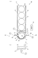
【解決手段】制御部36は、第2モータM2を駆動することで、(A)に示すように回転
テーブル312を例えば反時計回りに回転させる。これにより容器20も反時計回りに回
転する。その後、制御部36は、バーコード検知センサS1からの出力に基づき、容器2
0に付されたバーコードを検知できたか否かを判断する。そして、制御部36は、バーコ
ードが検知できたと判断した場合、第2モータM2を例えば所定のステップ数(または所
定時間)だけ駆動後、第2モータM2の駆動を停止させる。これにより、識別標記23が
前方を向いた状態となる。
【選択図】図2Provided is a display device capable of displaying a mark in a predetermined direction even when the container is placed in a random direction when the container is vertically displayed on the display device. .
A control unit 36 drives a second motor M2 to rotate a rotary table 312 counterclockwise, for example, as shown in FIG. As a result, the container 20 also rotates counterclockwise. Thereafter, the control unit 36 determines the container 2 based on the output from the barcode detection sensor S1.
It is determined whether or not the bar code attached to 0 has been detected. If the controller 36 determines that the bar code has been detected, the controller 36 drives the second motor M2 for a predetermined number of steps (or a predetermined time), and then stops driving the second motor M2. As a result, the identification mark 23 faces forward.
[Selection] Figure 2
Description
本発明は、容器の陳列を行う陳列装置に関する。 The present invention relates to a display device that displays containers.
例えばコンビニエンスストアなどにおいては、飲料缶やペットボトルなど飲料が充填さ
れた容器が、例えば陳列ケースに収容された陳列装置に縦置きに載せられて販売される。
そしてこのような陳列装置は、例えば、容器自身の自重により陳列ケースの前方に容器が
移動するように傾斜した状態で配置される。そして、手前側(最前列)の1つの容器を抜
き取ると、後続の容器が自重で手前側に移動する。
ここで陳列装置の容器が載せられる箇所には、容器の滑りの良さから例えばプラスチッ
クの平板が設けられる。また、近年では回転可能なローラを多数配置した陳列装置が出回
っている(例えば、特許文献1参照)。また、容器の補充は陳列装置の後方側から行うの
が一般的であるが、手前側からの容器の投入を可能とするとともに、奥側に移動した容器
が、再度手前側に移動し陳列される陳列装置も提案されている(例えば、特許文献2参照
)。即ち、前方側から投入された容器がUターンして戻ってくる陳列装置が提案されてい
る。さらに、容器に関するものとして、缶底に形成された環状凸部の内周壁に、内側凹部
と縦リブとが円周方向に交互に形成された缶が提案されている(例えば、特許文献3参照
)。
For example, in convenience stores and the like, containers filled with beverages such as beverage cans and plastic bottles are placed on a display device housed in a display case, for example, and placed on the market.
And such a display apparatus is arrange | positioned in the state inclined, for example so that a container might move ahead of a display case with dead weight of the container itself. When one container on the near side (front row) is extracted, the subsequent container moves to the near side by its own weight.
Here, a plastic flat plate, for example, is provided at a place where the container of the display device is placed because of the good sliding property of the container. In recent years, display devices in which a large number of rotatable rollers are arranged are on the market (for example, see Patent Document 1). In addition, the container is generally refilled from the rear side of the display device, but the container can be loaded from the front side, and the container moved to the back side is moved to the front side again and displayed. A display device has also been proposed (see, for example, Patent Document 2). That is, a display device has been proposed in which a container thrown in from the front side makes a U-turn and returns. Further, as a container, a can in which inner concave portions and vertical ribs are alternately formed in a circumferential direction on an inner peripheral wall of an annular convex portion formed on a can bottom has been proposed (see, for example, Patent Document 3). ).
ところで、容器の外面には、商品名や商標名など他の商品と識別するための標記が設け
られるが、この標記が購入者の取り出し方向に向いていないと、商品の識別がしにくくな
るとともに、商品の陳列時の見栄えが悪くなる。このため、陳列される容器は、例えば前
方側など、標記が所定の方向に向いていることが好ましい。
By the way, the outer surface of the container is provided with a mark for distinguishing it from other products such as a product name and a trade name, and it is difficult to identify the product if the mark is not suitable for the purchase direction of the purchaser. , The appearance at the time of display of the product becomes worse. For this reason, it is preferable that the container to be displayed is oriented in a predetermined direction such as the front side.
公報記載の従来技術として、容器が載せられる傾斜棚板の上面に、棚板傾斜方向に向け
て棒状のガイド凸条を設け、容器の底部に、標記の直下と標記が付された面とは反対側の
面の直下とを結ぶ凹状嵌合部を設け、このガイド凸条と凹状嵌合部とを用いて容器を陳列
する陳列方法が提案されている(例えば、特許文献4参照)。この陳列方法では、標記が
前方側を向く姿勢で凹状嵌合部をガイド凸条に嵌合させ、複数の容器を前後に並べる。こ
の結果、標記が前方を向いた状態で容器の陳列が行われる。
As the prior art described in the publication, on the top surface of the inclined shelf on which the container is placed, a bar-shaped guide ridge is provided in the inclination direction of the shelf, and the bottom of the container is directly below and the surface with the mark attached There has been proposed a display method in which a concave fitting portion is provided that connects directly below the opposite surface, and the container is displayed using the guide protrusion and the concave fitting portion (see, for example, Patent Document 4). In this display method, the concave fitting portion is fitted to the guide ridge in a posture in which the mark faces the front side, and a plurality of containers are arranged in the front-rear direction. As a result, the container is displayed with the mark facing forward.
上記特許文献4では、凹状嵌合部をガイド凸条に嵌合させ容器の陳列を行うことで、標
記を確実に前方に向けることが可能となる。しかしながら、かかる発明では、容器の投入
者は、容器を陳列装置に設置する度に凹状嵌合部をガイド凸条に嵌合させる必要があり、
容器の陳列作業が繁雑となる。また、標記が容器の一箇所にのみ形成されている場合には
、標記が後方側に向いた状態で陳列される陳列ミスの発生も懸念される。また、このコン
ビニエンスストアなどの多量の飲料を販売する店舗等では、向きを揃えて投入する作業が
非常に大掛かりとなる。
In Patent Document 4, the concave fitting portion is fitted to the guide ridge and the container is displayed, so that the mark can be reliably directed forward. However, in such an invention, the container supplier needs to fit the concave fitting portion to the guide ridge every time the container is installed in the display device.
Container display work becomes complicated. In addition, when the mark is formed only at one location of the container, there is a concern that a display error may occur in which the mark is displayed in the state of facing backward. In addition, in a store that sells a large amount of beverages such as this convenience store, the work of throwing in a uniform orientation becomes very large.
本発明は、容器を陳列装置に縦置きに陳列する際に容器の標記をランダムな方向に向け
て容器を置いても、標記を所定の方向に向けて陳列することが可能な陳列装置を提供する
ことを主たる目的とする。
The present invention provides a display device capable of displaying a mark in a predetermined direction even when the container is placed in a random direction when the container is vertically displayed on the display device. The main purpose is to do.
かかる目的のもと、本発明が適用される陳列装置は、他の商品と識別するための標記を
有し内部に飲料を有する容器を陳列する陳列装置であって、容器が載せられる載置部と、
載置部に載せられた容器における標記が特定の方向に向くように容器を回転させる回転手
段と、を含む。
For this purpose, the display device to which the present invention is applied is a display device for displaying a container having a mark for distinguishing it from other commodities and having a drink inside, and on which the container is placed When,
Rotating means for rotating the container so that the mark on the container placed on the mounting portion faces a specific direction.
ここで、回転手段は、載置部の少なくとも一部を回転させることで容器の回転を行うこ
とを特徴とすることができる。また、容器に付され標記と所定の位置関係を有したマーク
を検知するマーク検知手段を更に備え、回転手段は、回転させた容器の回転をマーク検知
手段による検知結果に基づき停止させ、標記を特定の方向に向けることを特徴とすること
ができる。さらに、マークは、容器に付されたバーコードであることを特徴とすることが
できる。また、載置部には複数の容器を載せることが可能であり、回転手段が回転を行う
容器と載置部に載せられた他の容器とを離間させる離間手段を更に備えることを特徴とす
ることができる。
Here, the rotating means can be characterized in that the container is rotated by rotating at least a part of the mounting portion. Further, it further comprises mark detection means for detecting a mark attached to the container and having a predetermined positional relationship with the mark, and the rotation means stops the rotation of the rotated container based on the detection result by the mark detection means, It can be characterized by being directed in a specific direction. Further, the mark may be a bar code attached to the container. In addition, it is possible to place a plurality of containers on the placement unit, and further includes a separation unit that separates the container that the rotation unit rotates and the other container placed on the placement unit. be able to.
さらに、回転手段は、容器の側部に接触可能な接触部材を備え、回転させた容器の側部
に接触部材を接触させることで回転を停止させ、標記を特定の方向に向けることを特徴と
することができる。また、回転手段は、載置部に載せられた容器の側部に接触し容器を容
器の取り出し部に向けて案内するとともに案内に伴い容器に回転力を付与する付与部と、
付与部により回転する容器の標記が特定の方向を向いた際に付与部と容器とを非接触状態
とし、付与部による容器の回転を停止させる回転停止部と、を備えていることを特徴とす
ることができる。
Further, the rotating means includes a contact member that can contact the side portion of the container, and the rotation is stopped by bringing the contact member into contact with the side portion of the rotated container, and the mark is directed in a specific direction. can do. Further, the rotating means contacts the side portion of the container placed on the mounting portion and guides the container toward the container take-out portion and gives a rotational force to the container along with the guidance,
A rotation stop unit that stops the rotation of the container by the applying unit when the marking of the container that is rotated by the applying unit is in a non-contact state when the mark of the container is directed in a specific direction. can do.
他の観点から捉えると、本発明が適用される陳列装置は、他の商品と識別するための標
記を有し飲料を内部に有する容器を陳列する陳列装置であって、傾斜して配置されること
により、載せられた容器を一方向に移動させる移動部材と、移動部材に載せられた容器に
おける標記が一方向を向くように容器を回転させる回転手段と、を含む。
From another point of view, the display device to which the present invention is applied is a display device for displaying a container having a mark for distinguishing it from other products and having a drink inside, and is disposed at an inclination. Thus, a moving member for moving the placed container in one direction and a rotating means for rotating the container so that the mark on the container placed on the moving member faces in one direction are included.
更に本発明を別の観点から捉えると、本発明が適用される陳列装置は、他の商品と識別
するための標記を有し飲料を内部に有する容器を購入者に対して陳列する陳列装置であっ
て、容器が載せられる載置部と、載置部に載置された容器における標記が購入者側を向く
ように容器を回転させる回転手段と、を含む。
また、本発明の陳列装置に使用される容器は、ICタグを装着した容器であることを特徴とすることができる。
Further, when the present invention is viewed from another viewpoint, the display device to which the present invention is applied is a display device for displaying a container having a mark for distinguishing it from other products and having a drink inside to a purchaser. And a placing unit on which the container is placed, and a rotating means for rotating the container so that the mark on the container placed on the placing unit faces the purchaser.
Moreover, the container used for the display apparatus of this invention can be characterized by being a container equipped with an IC tag.
容器を陳列装置に縦置きに陳列する際に容器の標記をランダムな方向に向けて容器を置
いても、標記を所定の方向に向けて陳列することが可能な陳列装置を提供することが可能
となる。
It is possible to provide a display device capable of displaying a mark in a predetermined direction even when the container is placed in a random direction when the container is displayed vertically on the display device. It becomes.
―第1の実施形態―
以下、添付図面を参照して、本発明を実施するための最良の形態について詳細に説明す
る。
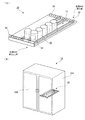
図1は、第1の実施形態に係る陳列装置の概略構成を説明するための図である。
同図(A)に示すように本実施形態における陳列装置30は、飲料が内部に充填された
容器20が載せられる載置部31と、容器20の移動経路(搬送経路)を形成するととも
に容器20の移動を案内するガイド32とを備えている。また、一部が透明に形成される
とともに載置部31の一側辺に沿って配置され、移動してきた容器20を停止させる規制
板34を備えている。ここでガイド32は、例えば、その両端部が載置部31に形成され
た開口33に差し込まれることにより載置部31に固定される。なお図1では、容器20
に円筒状の缶を例示しているが、所謂ペットボトルなどの樹脂製の容器やキャップを有し
た所謂ボトル缶なども用いることができる。
-First embodiment-
The best mode for carrying out the present invention will be described below in detail with reference to the accompanying drawings.
FIG. 1 is a diagram for explaining a schematic configuration of the display device according to the first embodiment.
As shown in FIG. 1A, the
Although a cylindrical can is illustrated as an example, a so-called bottle can having a cap made of resin such as a so-called plastic bottle or a cap can also be used.
ここで容器20の外周面には、通常、商品名や商標名など他の商品と識別するための識
別標記23が設けられる。なお、識別標記23の容器20への付与方法であるが、容器2
0が缶である場合、例えば塗装、印刷により付与することができる。また、容器20がペ
ットボトル等である場合には、識別標記23を有するフィルムを容器20に巻き付けた後
、このフィルムを熱収縮させることにより付与することができる。即ち、識別標記23は
、塗装、印刷のみならずフィルム等を別途装着等することによっても付与することができ
る。
Here, the outer peripheral surface of the
When 0 is a can, it can be applied by, for example, painting or printing. Moreover, when the
陳列装置30は、同図(B)に示すように、コンビニエンスストア、スーパーマーケッ
トなどに設置される陳列ケース10の内部に収納される。この陳列ケース10は、直方体
状に形成されたケース本体部10Aと、このケース本体部10Aに対して開閉可能に設け
られたドア10Bとにより主要部が構成されている。
ここで陳列装置30は、陳列ケース10に設けられた棚(不図示)の上に載せられる。
この際陳列装置30は、規制板34が設けられた側がドア10B側に位置するように設置
される。また、規制板34が設けられた側が、規制板34が設けられた側とは反対側より
も下方に位置するように配置される。即ち、陳列装置30は、陳列ケース10の後方側か
ら容器20が取り出される前方側(取り出し部側)に向かって下り傾斜した状態で配置さ
れる。
As shown in FIG. 2B, the
Here, the
At this time, the
ここで本実施形態における陳列ケース10は、後方側にもドアが設けられ(不図示)、
後方側も開放可能となっている。そしてこの後方側より陳列装置30に容器20が投入さ
れる。即ち、陳列ケース10の後方側および陳列装置30の後方側に容器20の投入部が
設けられた構成となっている。その後、この容器20は載置部31上をドア10B側(前
方側)に向かって移動する。即ち、容器20を購入する購入者側に向かって移動する。な
お、本明細書では、ドア10B側を前方側(前方)と称しドア10Bとは反対側を後方側
(後方)と称する場合がある。また、陳列ケース10の幅方向(容器20が移動する方向
に直交する方向)を横方向、幅方向と称する場合がある。
Here, the
The rear side can also be opened. And the
陳列装置30についてより詳細に説明する。
図2は、本実施形態における陳列装置30を説明するための図である。ここで、図2(
A)は陳列装置30の上面図であり、図2(B)は陳列装置30を前方から眺めた場合の
図である。なお図2(B)では、容器20の図示を省略している。
The
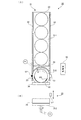
FIG. 2 is a diagram for explaining the
FIG. 2A is a top view of the
本実施形態における陳列装置30の載置部31には、前方側が後方側よりも下方に位置
するように配置され、即ち前方に向かって下り傾斜した状態で配置され、載せられた容器
20を前方に向けて移動させる底板311(移動部材の一例)が設けられている。なお底
板311には、ロール状の部材や球状部材など回転可能なローラを複数設けることが出来
る。また、底板311には、例えばアクリル板など表面が平滑な板状部材を用いることも
できる。
さらに載置部31には、底板311よりも前方に配置され、底板311から移動してき
た容器20が載せられる回転テーブル312が設けられている。この回転テーブル312
は、円盤状に形成され、周方向への回転が可能に配置されている。なおこの回転テーブル
312も、前方側が後方側よりも下方に位置するように配置されている。即ち前方に向か
って下り傾斜した状態で設けられている。
The
Further, the mounting
Is formed in a disk shape and is arranged to be rotatable in the circumferential direction. The
また陳列装置30は、底板311の前方側における端部に、容器20の移動経路上に向
かって突出するとともにこの移動経路から退避可能に設けられた突出部材35を備えてい
る。また、突出部材35の突出/退避を行う第1モータM1を備えている。さらに、陳列
装置30は、回転テーブル312の回転を行う第2モータM2(同図(B)参照)と、容
器20に付されたバーコードを検知するバーコード検知センサS1(マーク検知手段の一
例)とを備えている。さらに陳列装置30は、回転テーブル312上における容器20の
有無を検知する有無検知センサS2を備えている。また陳列装置30は、第1モータM1
、第2モータM2等を制御する制御部36を備えている。なお図中、制御部36は、容器
20の移動経路の側方に配置されているが、この配置位置は一例である。例えば、底板3
11の下方に配置することもできる。
In addition, the
And a
11 can also be disposed below.
ここで容器20の外面には、上記のとおり、商品名や商標名など他の商品と識別するた
めの識別標記23が設けられる(図1(A)も参照)。ところでこの識別標記23が購入
者の取り出し方向に向いていないと、商品の識別がしにくくなるとともに商品の陳列時の
見栄えが悪くなる。このため、陳列される容器20は、識別標記23が前方を向いた状態
で陳列されることが好ましい。そこで、本実施形態では、識別標記23が前方を向くよう
に容器20を回転させる処理を行っている。
Here, as described above, the
なおバーコードは、容器20の一定位置に付されるとは限らない。即ち、バーコードは
、容器20の種類が異なる場合、高さ方向の異なる位置に付される場合がある。付言すれ
ばある種類の容器20では低い位置に付され、他の種類の容器20では高い位置に付され
る場合がある。そしてこのような場合、バーコード検知センサS1が一定位置に固定され
ていると、バーコードの検知が困難となってしまう。そこで、本実施形態では、同図(B
)に示すように、バーコード検知センサS1を、上下方向(容器20の高さ方向)のスラ
イドが可能なように配置している。
The bar code is not always attached to a certain position of the
), The barcode detection sensor S1 is arranged so as to be slidable in the vertical direction (the height direction of the container 20).
この結果、容器20が他の種類に変更されたとしても、バーコード検知センサS1の位
置を変更することで、バーコードを適切に検知可能となる。なお、バーコード検知センサ
S1が、容器20の移動経路の中央部に位置していると、バーコード検知センサS1によ
り識別標記23の視認性が悪化するおそれがある(識別標記23が隠れてしまうおそれが
ある)。このため、本実施形態では、同図(A)、(B)に示すように、バーコード検知
センサS1を容器20の移動経路の側方に配置している。付言すれば、バーコード検知セ
ンサS1を、容器20の移動経路の中央部から外れた位置に配置している。
As a result, even if the
ここで図3は、制御部36の制御ブロックを示した図である。なお、本図では、容器2
0の回転制御に関するブロックのみを図示している。
制御部36は、CPU(Central Processing Unit)361、ROM(Read Only Memory)
362、RAM(Random Access Memory)363を備える。制御部36のCPU361は、
ROM362に記憶されたプログラムに従い、RAM363との間で適宜データのやりと
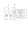
りを行いながら所定の処理を実行する。ここで、制御部36には、入出力インターフェー
ス364を介して、バーコード検知センサS1からの出力、有無検知センサS2からの出
力が入力される。また、制御部36は、入出力インターフェース364を介して、第1モ
ータM1および第2モータM2を制御する。
Here, FIG. 3 is a diagram showing a control block of the
Only the blocks relating to the zero rotation control are shown.
The
362 and a RAM (Random Access Memory) 363. The
In accordance with a program stored in the
続いて、制御部36が行う処理についてより具体的に説明する。
ここで図4は、制御部36が行う処理の手順の一例を示したフローチャートである。制
御部36が行う処理を図2とともに説明する。
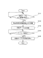
制御部36は、有無検知センサS2からの出力を監視しており、この出力に基づき回転
テーブル312から容器20が取り除かれたか否かを判断する(ステップ101)。そし
て、制御部36は、容器20が取り除かれたと判断した場合、第1モータM1を駆動させ
ることで、突出部材35を容器20の移動経路上から所定時間だけ退避させる(ステップ
102)。これによって、図2(A)に示すように、1つの容器20のみが回転テーブル
312上に載るようになる。なお回転テーブル312に1つの容器20が載せられた後、
この容器20と後続の容器20との接触は突出部材35により阻止される。付言すれば回
転テーブル312に載せられた容器20と後続する容器20とが離間した状態となる。こ
のため、回転テーブル312上の容器20の回転(後述する)を円滑に行うことができる
。ここで本実施形態における突出部材35は、回転テーブル312に載せられた容器20
と後続する容器20とを離間させる離間手段として捉えることができる。
Next, the process performed by the
Here, FIG. 4 is a flowchart showing an example of a procedure of processing performed by the
The
Contact between the
And the following
次いで、回転手段の1つとして機能する制御部36は、第2モータM2を駆動すること
で、図2(A)に示すように、回転テーブル312を例えば反時計回りに回転させる(ス
テップ103)。これにより容器20も反時計回りに回転するようになる。なお、回転テ
ーブル312は、上記のように、前方に向かって下り傾斜した状態で設けられている。こ
のため、回転テーブル312上の容器20は、規制板34に接触した状態で回転を行う。
Next, the
その後、制御部36は、バーコード検知センサS1からの出力に基づき、容器20に付
されたバーコード(図2(A)中符号BKで表示)を検知できたか否かを判断する(ステ
ップ104)。そして、制御部36は、バーコードが検知できたと判断した場合、第2モ
ータM2を例えば所定のステップ数(または所定時間)だけ駆動後、第2モータM2の駆
動を停止させる。即ち制御部36は、第2モータM2を例えば所定のステップ数(または
所定時間)だけ駆動後に第2モータM2を停止させることで、回転テーブル312の回転
を停止させる(ステップ105)。そして、これら一連の処理により、識別標記23が前
方を向いた状態となる(図1(A)における最前部の容器20参照)。
Thereafter, the
ところで容器20における識別標記23とバーコードは、通常、所定の位置関係を有し
ている。そこで、例えばROM362に、バーコートの検知タイミングから第2モータM
2の駆動を停止させるまでのステップ数(時間)を予め記憶しておく。そして、制御部3
6は、ROM362に記憶されたこれらの情報(ステップ数や時間)をもとに、第2モー
タM2の制御を行い、識別標記23が前方を向くように回転テーブル312の回転を停止
させる。
なお、バーコードは、容器20の種類が異なる場合、上述のように高さ方向の異なる位
置に付される場合がある。またバーコードは、容器20の種類が異なる場合、円周方向に
おいても異なる位置に付される場合がある。このため、陳列する容器20の種類に応じて
、事前に、バーコード検知センサS1の位置修正と、上記ステップ数等に関する設定の変
更とを行っておく必要がある。また、バーコードは、識別標記23の位置確認のために用
いるものであるので、バーコード全体ではなくバーコードの一部を認識(読み込めれば)
できればよい。またバーコード検知センサS1には、画像カメラのような光学的手段を用
いることもできるし、バーコードリーダなども用いることもできる。なお、市場に広く出
回っており既成のものが利用できる点でバーコードリーダを用いることがより簡便である
。
By the way, the
The number of steps (time) until the driving of 2 is stopped is stored in advance. And the control part 3
6 controls the second motor M2 based on these pieces of information (number of steps and time) stored in the
In addition, when the kind of
I can do it. For the barcode detection sensor S1, optical means such as an image camera can be used, and a barcode reader can also be used. Note that it is easier to use a barcode reader because it is widely available in the market and ready-made ones can be used.
なお、上記では、突出部材35を所定時間だけ退避させることで1つの容器20のみを
前方に供給した。ここで例えば、移動経路から退避している突出部材35の上を容器20
が通過したか否かを検知する通過検知センサ(不図示)をさらに設けることもできる。そ
して、例えば、この通過検知センサにて容器20の通過が検知された場合に、突出部材3
5を突出させることができる。この場合、1つの容器20のみをより正確に前方側に供給
可能となる。また、本実施形態では突出部材35の進退を第1モータM1により行う例を
説明したが、モータに限られず他の駆動源(例えばソレノイド)を用いることもできる。
In the above description, only one
It is also possible to further provide a passage detection sensor (not shown) for detecting whether or not the passage has passed. For example, when the passage of the
5 can be projected. In this case, only one
また、本実施形態では、バーコードの検知結果に基づき容器20の回転を停止させたが
、バーコードに限られず、識別標記23と所定の位置関係を有しているマークを検知し、
この検知結果に基づき容器20の回転停止を行うこともできる。また、例えば識別標記2
3と所定の位置関係を有して配置され、また容器20の製造メーカにより付され且つ定形
化されたマーク(メーカーマーク)を検知し、この検知結果に基づき容器20の回転停止
を行うこともできる。さらに、識別標記23と所定の位置関係を有した突起や凹部を検知
し、この検知結果に基づき容器20の回転停止を行うこともできる。
Further, in the present embodiment, the rotation of the
The rotation of the
3, and a mark (manufacturer mark) that is arranged and shaped by the manufacturer of the
さらに、上記では回転テーブル312が、容器20の移動経路における最下流側、即ち
、容器20の取り出し部に設けられていたが、このような形態に限られない。例えば、容
器20の投入部、即ち、容器20の移動経路における最上流側に設けることもできる。そ
してこの場合、上記と同様、回転テーブル312により、識別標記23が前方(取り出し
部側)を向くように容器20が回転される。そして回転後に、前方への容器20の移動が
開始される。また、回転テーブル312は、上記取り出し部や投入部に限られず、例えば
容器20の移動経路の途中に設けることもできる。
Further, in the above description, the rotary table 312 is provided on the most downstream side in the movement path of the
また本実施形態では、容器20の下方に位置する回転テーブル312を用い、即ち容器
20の底部を介して容器20を回転させたが、他の形態により回転させることができる。
例えば、モータ等の駆動源により回転する回転ローラを容器20の側部に接触させ、容器
20の側部を介して容器20の回転を行うこともできる。さらに、例えば、容器20の上
面(蓋)から突出する上記プルタブに接触しこのプルタブを介して容器20に駆動力を与
え、容器20の回転を行うことができる。
Further, in this embodiment, the rotary table 312 located below the
For example, a rotating roller rotated by a driving source such as a motor may be brought into contact with the side portion of the
―第2の実施形態―
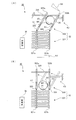
ここで図5は、第2の実施形態における陳列装置30を示した図である。なお図5(A
)は陳列装置30の上面図であり、図5(B)は陳列装置30を前方から眺めた場合の図
である。ここで図5(B)では容器20の図示を省略している。また第1の実施形態と同
様の機能については同様の符号を用いここではその説明を省略する。
-Second Embodiment-
Here, FIG. 5 is a diagram illustrating the
) Is a top view of the
本実施形態における規制板34は、同図(A)に示すように、陳列装置30の前方に向
かって凸となるように円弧状に形成されている。また回転テーブル312の外周縁に沿う
ように配置されている。さらに、規制板34は、内周面側(容器20と接触する側)に、
回転可能に設けられた球状部材341(例えばベアリング)を複数備えている。なお、本
形態では球状部材341を例示するが、回転可能なローラ状の部材を用いることもできる
。
The
A plurality of spherical members 341 (for example, bearings) provided rotatably are provided. In this embodiment, the
ここで本実施形態における回転テーブル312も、第1の実施形態と同様に、前方側が
後方側よりも下方に位置するように配置されている。即ち、前方に向かって下り傾斜した
状態で配置されている。このため、容器20は、回転テーブル312上で、前方側(規制
板34側)に位置するようになる。また、上記のように、規制板34は前方に向かって凸
となる円弧状に形成されている。このため、回転テーブル312上で回転する容器20は
、規制板34の略中央部に位置決めされることとなる。このため、容器20がより安定的
に回転するようになり、バーコード検知センサS1によるバーコードの検知精度をより高
めることができる。
Here, similarly to the first embodiment, the
さらに、本実施形態では上記のように、規制板34の内周面側に球状部材341が複数
設けられている。このため本実施形態では、容器20がより安定的に回転するようになる
。
なお、本実施形態においても、バーコード検知センサS1を、上下方向(容器20の高
さ方向)のスライドが可能なように配置している。また、バーコード検知センサS1を、
容器20の移動経路の中央部から外れた位置に配置している。
Furthermore, in this embodiment, as described above, a plurality of
Also in this embodiment, the barcode detection sensor S1 is arranged so as to be slidable in the vertical direction (the height direction of the container 20). In addition, the barcode detection sensor S1
It arrange | positions in the position which remove | deviated from the center part of the movement path | route of the
ところで、上記第1の実施形態では、第2モータM2の駆動制御(駆動停止)により、
容器20の停止を行った。一方で、本実施形態では、容器20の回転を停止させる停止機
構38を別途設けることで容器20の回転を停止させている。
By the way, in the first embodiment, by the drive control (drive stop) of the second motor M2,
The
ここで本実施形態における停止機構38は、容器20の移動経路を挟み一方側に配置さ
れ、この一方側から容器20の移動経路上(詳細には回転テーブル312上)に突出する
第1突出部材381を備える。また、停止機構38は、容器20の移動経路を挟み他方側
に配置され、この他方側から容器20の移動経路上(詳細には回転テーブル312上)に
突出する第2突出部材382を備える。さらに、停止機構38は、第1突出部材381を
移動経路上に突出させる第1駆動源K1、第2突出部材382を移動経路上に突出させる
第2駆動源K2を備えている。なお、容器20と第1突出部材381等との接触面積を確
保するため、第1突出部材381および第2突出部材382は、同図(A)に示すように
略T字状に形成することが好ましい。また、第1突出部材381および第2突出部材38
2の各々は、容器20と接触する箇所を、容器20の表面形状に倣った形状(例えば円弧
形状)とすることが好ましい。
ここで第1突出部材381および第2突出部材382は、通常、コイルスプリングなど
の付勢部材により容器20の移動経路上から退避している。そして、第1駆動源K1、第
2駆動源K2が制御部36によりオンされると、容器20の移動経路上に突出する。なお
、第1駆動源K1、第2駆動源K2には、例えばソレノイドを用いることができる。
Here, the
It is preferable that each of 2 makes the location which contacts the
Here, the first projecting
ここで、本実施形態では、上記ステップ101〜ステップ104と同様の処理が行われ
る。但し、ステップ104にてバーコードが検知された場合、制御部36は、バーコード
が検知されてから所定時間経過後、第1駆動源K1、第2駆動源K2をオンとし、第1突
出部材381および第2突出部材382を容器20の移動経路上に突出させる。
これによって図5(A)に示すように、接触部材として機能する第1突出部材381お
よび第2突出部材382が容器20の側部に接触し、容器20の回転が停止される。付言
すれば、容器20が第1突出部材381および第2突出部材382により挟まれ、容器2
0の回転が停止される。そして図1(A)にも示したように、識別標記23が前方を向い
た状態となる。
なお、制御部36は、その後、第2モータM2の駆動を停止させることで回転テーブル
312の回転を停止させる。次いで、第1駆動源K1、第2駆動源K2をオフとし、第1
突出部材381および第2突出部材382を容器20の移動経路上から退避させる。これ
により、陳列装置30からの容器20の取り出しが可能となる。
Here, in the present embodiment, the same processing as in the above-described steps 101 to 104 is performed. However, when a barcode is detected in step 104, the
As a result, as shown in FIG. 5A, the first projecting
Zero rotation is stopped. Then, as shown in FIG. 1A, the
In addition, the
The protruding
―第3の実施形態―
ここで図6は、第3の実施形態における陳列装置30を示した上面図である。
同図(A)に示すように、本実施形態におけるガイド32は、前方側ガイド321と、
この前方側ガイド321よりも後方に設けられた後方側ガイド322とから構成されてい
る。
ここで前方側ガイド321は、容器20の移動経路の左方側(一方側)に配置された第
1ガイド部材321aと、移動経路の右方側(他方側)に配置された第2ガイド部材32
1bとから構成されている。そしてこの前方側ガイド321は、この第1ガイド部材32
1aおよび第2ガイド部材321bを用い、容器20の移動経路(以下、この移動経路を
「前方側移動経路」と称する)を形成している。なお、第1ガイド部材321aおよび第
2ガイド部材321bは、陳列装置30の前後方向に沿って設けられている。このため、
上記前方側移動経路も陳列装置30の前後方向に沿った状態となっている。
-Third embodiment-
FIG. 6 is a top view showing the
As shown in FIG. 4A, the
The
Here, the
1b. The
1a and the
The front side movement path is also in a state along the front-rear direction of the
一方、後方側ガイド322は、前方側ガイド321と同様に、容器20の移動経路の左
方側(一方側)および右方側(他方側)に、ガイド部材を備えている。なお、本明細書で
は、左方側のガイド部材を第3ガイド部材322aと称し、右方側のガイド部材を第4ガ
イド部材322bと称する。そして、後方側ガイド322は、この第3ガイド部材322
aおよび第4ガイド部材322bを用い、容器20の移動経路(以下、この移動経路を「
後方側移動経路」と称する)を形成している。なお、第3ガイド部材322aおよび第4
ガイド部材322bは、陳列装置30の前後方向に対し傾きを有した状態で設けられてい
る。このため、後方側移動経路も陳列装置30の前後方向に対し傾きを有した状態となっ
ている。
On the other hand, the
a and the
This is referred to as a “rear-side movement path”. The
The
ここで、第3ガイド部材322aの前端部と第1ガイド部材321aの後端部とは、ヒ
ンジ323を介して接続されている。そして、第3ガイド部材322aは、このヒンジ3
23を中心として回転(揺動)可能となっている。また、第4ガイド部材322bの前端
部と第2ガイド部材321bの後端部もヒンジ324を介して接続されている。そして、
第4ガイド部材322bは、このヒンジ324を中心として回転(揺動)可能となってい
る。
Here, the front end of the
It is possible to rotate (swing) about the
The
また本実施形態では、第3ガイド部材322aおよび第4ガイド部材322bの両者に
取り付けられ、両者を連動させる連動部材325が設けられている。さらに本実施形態で
は、第4ガイド部材322bを側方から押圧し、ヒンジ324を中心として第4ガイド部
材322bを回転させる駆動源K3が設けられている。なおこの駆動源K3には、例えば
エアシリンダやソレノイドを用いることができる。また本実施形態では、第4ガイド部材
322bに、上記と同様、容器20に付されたバーコードを検知するバーコード検知セン
サS1が設けられている。
Moreover, in this embodiment, the interlocking
さらに本実施形態では、同図(A)の符号6Aに示すように、後方側移動経路は、第4
ガイド部材322b側の方が第3ガイド部材322a側よりも下方に位置するように傾斜
した状態で形成されている。即ち、後方側移動経路は、移動経路の幅方向に傾斜が付与さ
れた状態となっている。なお、前方側ガイド321により形成される前方側移動経路は、
同図(A)の符号6Bに示すように、幅方向における傾斜が付与されていない状態となっ
ている。
Furthermore, in this embodiment, as shown to the code |
The
As indicated by
ここで、後方側移動経路に投入された容器20は、前方への移動を開始する。この際、
容器20は、後方側移動経路に幅方向の傾斜が付与されているため、第4ガイド部材32
2bに接触するとともにこの第4ガイド部材322bから抗力を受ける状態となる。この
ため、容器20は、反時計回り方向に回転しながら前方へ移動していく(同図(A)参照
)。言い換えると、付与部の一例としての第4ガイド部材322bは、容器20の側部に
接触し、容器20を前方に向けて案内するとともに、この案内に伴い容器20に回転力を
付与している。
Here, the
Since the
2b and contact with the
その一方で、制御部36は、バーコード検知センサS1からの出力を監視している。そ
して、制御部36は、バーコードを検知した場合、この検知から所定時間経過後に、駆動
源K3をオンとする。この結果、同図(B)に示すように、第4ガイド部材322bの回
転が行われる。これにより、第4ガイド部材322bが容器20を後方側移動経路の中央
部方向に押しだすこととなる。そして、容器20は、第4ガイド部材322bから離れる
とともに、識別標記23が前方を向いた状態で前方側移動経路に進入する。その後、容器
20は、識別標記23が前方を向いた状態を維持したままさらに前方へ移動していく。こ
こで駆動源K3は、容器20の識別標記23が前方を向いた際に、第4ガイド部材322
bと容器20と非接触状態とし容器20の回転を停止させる回転停止部として捉えること
ができる。
On the other hand, the
b and the
なお、本実施形態では、第3ガイド部材322aと第4ガイド部材322bとを連動さ
せる連動部材325が上記の通り設けられている。このため、第4ガイド部材322bが
回転する際、第3ガイド部材322aも回転するようになる。このため、第4ガイド部材
322bから離れた容器20と第3ガイド部材322aとの接触を防止でき、識別標記2
3が意図しない方向に向くことを防止できる。
In the present embodiment, the interlocking
3 can be prevented from facing in an unintended direction.
なお、本実施形態では、前方側移動経路および後方側移動経路を有した移動経路が陳列
装置30の幅方向に複数設けられている。そして、各々の移動経路に、バーコード検知セ
ンサS1が設けられている。このため、他の移動経路においても、識別標記23を前方に
向けることができる。なお、駆動源K3は、複数の移動経路の各々に対応して設けられて
いない。即ち1つの駆動源K3のみが設けられている。そして本実施形態では、各移動経
路に設けられ容器20を押し出すガイド部材に対し、連動部材325を用い駆動力を供給
する。このため駆動源の削減が可能となり、陳列装置30をより安価に構成可能となる。
In the present embodiment, a plurality of movement paths having a front movement path and a rear movement path are provided in the width direction of the
在庫あるいは、販売の数量を含めた商品管理に最近ICタグが使用されているが、本発明の容器20にこれを組み込み、陳列システムの中の付加機能の一つとして利用できる。例えば、本システムを使用する装置、容器を用いれば容器の取出し口において、標記23に対応する位置に容器方向を向かせることができるので、ICタグの位置を標記と一定関係の位置に置けば近接した陳列装置の位置にリーダ・ライタを置くことができる。これにより、顧客の出し入れのリアルタイムでの動きを把握することができる。
Recently, an IC tag has been used for merchandise management including inventory or sales quantity, but it can be incorporated into the
ICタグは、例えばペットボトルのような場合は、フィルムのような包装体に事前に接着したものを容器20の側面に巻き付け、あるいはキャップ内部に挿入することが出来る。また、缶のような容器では、側面に貼付したり、タブ部分に埋め込む等の方法にていずれも各容器一個ごとに装着することができる。
リーダ・ライタは、取出し口付近の一定位置に置けば、本システムを使用した場合、ほぼ定位置に容器20の標記23が向くので標記と一定関係部分にICタグを設置することで、リーダ・ライタを固定設定することができオンラインで容器の動きが手作業をすることなく把握できる。
For example, in the case of a PET bottle, the IC tag can be wrapped around a side surface of the
If the reader / writer is placed at a fixed position near the outlet, when the system is used, the
リーダ・ライタからのデータ情報は、ホストコンピューターにて一括処理・管理され販売・在庫等の管理データとして活用される。 Data information from the reader / writer is collectively processed and managed by the host computer and used as management data for sales and inventory.
20…容器、23…識別標記、30…陳列装置、31…載置部、35…突出部材、36…
制御部、311…底板、322b…第4ガイド部材、381…第1突出部材、382…第
2突出部材、K3…駆動源、S1…バーコード検知センサ
DESCRIPTION OF
Control unit, 311 ... bottom plate, 322b ... fourth guide member, 381 ... first protrusion member, 382 ... second protrusion member, K3 ... drive source, S1 ... bar code detection sensor
Claims (10)
って、
前記容器が載せられる載置部と、
前記載置部に載せられた前記容器における前記標記が特定の方向に向くように当該容器
を回転させる回転手段と、
を含む陳列装置。 A display device for displaying a container having a mark for distinguishing it from other products and having a drink inside,
A placement section on which the container is placed;
Rotating means for rotating the container so that the mark on the container placed on the mounting portion is directed in a specific direction;
Including display device.
うことを特徴とする請求項1記載の陳列装置。 The display device according to claim 1, wherein the rotation unit rotates the container by rotating at least a part of the placement unit.
を更に備え、
前記回転手段は、回転させた前記容器の回転を前記マーク検知手段による検知結果に基
づき停止させ、前記標記を前記特定の方向に向けることを特徴とする請求項1又は2に記
載の陳列装置。 A mark detecting means for detecting a mark attached to the container and having a predetermined positional relationship with the mark;
The display device according to claim 1, wherein the rotation unit stops rotation of the rotated container based on a detection result of the mark detection unit, and directs the mark in the specific direction.
陳列装置。 The display device according to claim 3, wherein the mark is a bar code attached to the container.
前記回転手段が回転を行う前記容器と前記載置部に載せられた他の容器とを離間させる
離間手段を更に備えることを特徴とする請求項1乃至4のいずれかに記載の陳列装置。 It is possible to place a plurality of the containers on the mounting portion,
The display device according to claim 1, further comprising a separation unit that separates the container that the rotation unit rotates and the other container placed on the placement unit.
前記容器の側部に接触可能な接触部材を備え、回転させた当該容器の当該側部に当該接
触部材を接触させることで当該回転を停止させ、前記標記を前記特定の方向に向けること
を特徴とする請求項1乃至5のいずれかに記載の陳列装置。 The rotating means includes
A contact member capable of contacting the side portion of the container is provided, the rotation is stopped by bringing the contact member into contact with the side portion of the rotated container, and the mark is directed in the specific direction. The display device according to any one of claims 1 to 5.
前記載置部に載せられた前記容器の側部に接触し当該容器を当該容器の取り出し部に向
けて案内するとともに当該案内に伴い当該容器に回転力を付与する付与部と、
前記付与部により回転する前記容器の前記標記が前記特定の方向を向いた際に当該付与
部と当該容器とを非接触状態とし、当該付与部による当該容器の回転を停止させる回転停
止部と、
を備えていることを特徴とする請求項1記載の陳列装置。 The rotating means includes
An imparting unit that contacts a side portion of the container placed on the placement unit and guides the container toward the container take-out unit and applies a rotational force to the container with the guidance;
A rotation stop unit for bringing the application unit and the container into a non-contact state when the mark of the container rotated by the application unit is in the specific direction, and stopping rotation of the container by the application unit;
The display device according to claim 1, further comprising:
って、
傾斜して配置されることにより、載せられた前記容器を一方向に移動させる移動部材と
、
前記移動部材に載せられた前記容器における前記標記が前記一方向を向くように当該容
器を回転させる回転手段と、
を含む陳列装置。 A display device for displaying a container having a mark for distinguishing it from other products and having a drink inside,
A moving member for moving the placed container in one direction by being disposed at an inclination;
Rotating means for rotating the container so that the mark on the container placed on the moving member faces the one direction;
Including display device.
る陳列装置であって、
前記容器が載せられる載置部と、
前記載置部に載置された前記容器における前記標記が前記購入者側を向くように当該容
器を回転させる回転手段と、
を含む陳列装置。 A display device for displaying to a purchaser a container having a mark for distinguishing from other products and having a drink inside,
A placement section on which the container is placed;
Rotating means for rotating the container so that the mark on the container placed on the placing portion faces the purchaser side;
Including display device.
Priority Applications (1)
| Application Number | Priority Date | Filing Date | Title |
|---|---|---|---|
| JP2008326196A JP2010142591A (en) | 2008-12-22 | 2008-12-22 | Display device |
Applications Claiming Priority (1)
| Application Number | Priority Date | Filing Date | Title |
|---|---|---|---|
| JP2008326196A JP2010142591A (en) | 2008-12-22 | 2008-12-22 | Display device |
Publications (1)
| Publication Number | Publication Date |
|---|---|
| JP2010142591A true JP2010142591A (en) | 2010-07-01 |
Family
ID=42563618
Family Applications (1)
| Application Number | Title | Priority Date | Filing Date |
|---|---|---|---|
| JP2008326196A Pending JP2010142591A (en) | 2008-12-22 | 2008-12-22 | Display device |
Country Status (1)
| Country | Link |
|---|---|
| JP (1) | JP2010142591A (en) |
-
2008
- 2008-12-22 JP JP2008326196A patent/JP2010142591A/en active Pending
Similar Documents
| Publication | Publication Date | Title |
|---|---|---|
| JP6202702B1 (en) | Product display system | |
| US20240321064A1 (en) | Lottery ticket vending machine | |
| JP4242921B1 (en) | Display device | |
| CN111968307A (en) | Medicine taking method of intelligent medicine selling equipment | |
| JP2010168114A (en) | Method and system for manufacturing can body | |
| JP4242919B1 (en) | Display device and display system | |
| JP5154821B2 (en) | Dispensing device cassette recognition method and apparatus | |
| JP4242920B1 (en) | Display system and display device | |
| JP4279895B1 (en) | Display system and display device | |
| JP2008094541A (en) | Sorting cart and sorting system | |
| CA3242995A1 (en) | Automatic labeling system | |
| JPH11250342A (en) | Commodity carrying device for vending machine | |
| JP2010142583A (en) | Display device and display system | |
| JPH11161843A (en) | vending machine | |
| JP2010142568A (en) | Display system, display device, and container | |
| JP2010143638A (en) | Displaying system, displaying device and container | |
| JP4238738B2 (en) | vending machine | |
| JP2010142569A (en) | Display device and display system | |
| JP2010142589A (en) | Container for drinks | |
| JP4203118B1 (en) | Beverage container | |
| JP4242918B1 (en) | Display device and display system | |
| JP2010142614A (en) | Display system and display device | |
| JP2010168115A (en) | Method and system for manufacturing resin-made container, and container for beverage | |
| JP2010142590A (en) | Display system and display device | |
| JP2010143636A (en) | Beverage container and fitting member |