JP2010143065A - Liquid discharge method and liquid discharge device - Google Patents
Liquid discharge method and liquid discharge device Download PDFInfo
- Publication number
- JP2010143065A JP2010143065A JP2008322396A JP2008322396A JP2010143065A JP 2010143065 A JP2010143065 A JP 2010143065A JP 2008322396 A JP2008322396 A JP 2008322396A JP 2008322396 A JP2008322396 A JP 2008322396A JP 2010143065 A JP2010143065 A JP 2010143065A
- Authority
- JP
- Japan
- Prior art keywords
- liquid chamber
- liquid
- individual liquid
- diaphragm
- drive signal
- Prior art date
- Legal status (The legal status is an assumption and is not a legal conclusion. Google has not performed a legal analysis and makes no representation as to the accuracy of the status listed.)
- Pending
Links
Images


Landscapes
- Particle Formation And Scattering Control In Inkjet Printers (AREA)
- Coating Apparatus (AREA)
Abstract
【課題】液体を吐出する吐出口と、吐出口と連通する個別液室と、個別液室の内側面の一部をなす振動板と、該振動板を変形させることで前記個別液室の容積を変化させるアクチュエータと、を備え、アクチュエータに個別液室を膨張、収縮、再膨張、再収縮させるための駆動信号を入力することで液体を吐出させる液体吐出方法において、駆動信号入力完了後のメニスカスのオーバーシュートを防止して、突き出し液柱の屈曲を要因とした液体吐出方向の偏向を抑制する。
【解決手段】上記駆動信号入力完了後に出現する振動板の極小変位に対し、当該出現後から吐出口側にて液柱切断部が観察される時点までの振動板変位が極小変位を下回らないように、個別液室を膨張させるための波形部分と、個別液室を初期容積に戻すための波形部分とを含む補助駆動信号をアクチュエータに入力する。
【選択図】図7Disclosed is a discharge port for discharging a liquid, an individual liquid chamber communicating with the discharge port, a diaphragm forming a part of an inner surface of the individual liquid chamber, and a volume of the individual liquid chamber by deforming the diaphragm. In a liquid discharge method for discharging liquid by inputting a drive signal for expanding, contracting, re-expanding, and re-contracting an individual liquid chamber to the actuator, a meniscus after completion of input of the drive signal is provided. The overshooting of the liquid is prevented, and the deflection of the liquid ejection direction due to the bending of the protruding liquid column is suppressed.
With respect to the minimal displacement of the diaphragm that appears after the completion of the drive signal input, the displacement of the diaphragm from the appearance until the time when the liquid column cutting portion is observed on the discharge port side does not fall below the minimal displacement. In addition, an auxiliary drive signal including a waveform portion for expanding the individual liquid chamber and a waveform portion for returning the individual liquid chamber to the initial volume is input to the actuator.
[Selection] Figure 7
Description
本発明は、液体吐出方法および液体吐出装置に関する。特に本発明は、液体を吐出するための吐出口とこれに連通する個別液室とを具え、この個別液室の一部を構成する振動板をアクチュエータにより変形させることで液体を吐出させる液体吐出方法および液体吐出装置に関する。そして本発明は、紙,布,皮革,不織布,OHP用プラスチックフィルム等の記録媒体に記録を行う機器だけでなく、基板,板材,固体物等に液体を付着させることでパターニングや加工を行う装置、さらには塗装装置等にも適用可能なものである。 The present invention relates to a liquid ejection method and a liquid ejection apparatus. In particular, the present invention provides a liquid discharge device that includes a discharge port for discharging a liquid and an individual liquid chamber that communicates with the discharge port, and discharges liquid by deforming a diaphragm that forms a part of the individual liquid chamber by an actuator. The present invention relates to a method and a liquid ejection apparatus. The present invention is not only a device for recording on a recording medium such as paper, cloth, leather, nonwoven fabric, and OHP plastic film, but also an apparatus for patterning and processing by attaching a liquid to a substrate, a plate material, a solid material, etc. Furthermore, it can also be applied to a coating apparatus or the like.
従来より、電圧パルスの印加により変形する圧電素子を利用して液体(インクなど)を吐出する液体吐出ヘッドが知られている。かかる液体吐出ヘッドでは、液体を吐出する吐出口と、その吐出口と連通する個別液室とを備え、個別液室の側面の一部に振動板が配置されている。そして、圧電素子の変形により振動板を変形させて、個別液室の内容積の変化(膨張または収縮など)を生じさせることで液体を吐出する。圧電素子の変形を利用する方式としては、圧電素子の軸方向に伸張・収縮を生じさせる縦振動を利用するタイプや、圧電素子のたわみを利用するタイプ(以下、ベンダー型と称する)がある(例えば特許文献1参照)。 2. Description of the Related Art Conventionally, a liquid discharge head that discharges liquid (such as ink) using a piezoelectric element that is deformed by application of a voltage pulse is known. Such a liquid discharge head includes a discharge port for discharging a liquid and an individual liquid chamber communicating with the discharge port, and a diaphragm is disposed on a part of the side surface of the individual liquid chamber. Then, the diaphragm is deformed by the deformation of the piezoelectric element, and the liquid is discharged by causing a change (expansion or contraction, etc.) of the internal volume of the individual liquid chamber. As a method using deformation of a piezoelectric element, there are a type using longitudinal vibration that causes expansion / contraction in the axial direction of the piezoelectric element, and a type using bending of the piezoelectric element (hereinafter referred to as a vendor type) ( For example, see Patent Document 1).
圧電素子を使用した液体吐出ヘッドを使用して液滴を吐出させる代表的な方法の1つとして、個別液室の容積を「膨張−収縮−再膨張−再収縮」の順序で変化させるものがある。このような容積変化によって液体吐出ヘッドから吐出される液体は、柱状に伸びた後に途中で分断され、これにより分離した液滴が記録媒体などの受容体に到達する。そして特許文献1には、柱状に伸びた液体(液柱)が分断され、液滴が千切れる時刻は「再膨張」のプロセス中である旨が開示されている。
One of the typical methods for ejecting liquid droplets using a liquid ejection head using a piezoelectric element is to change the volume of individual liquid chambers in the order of “expansion-contraction-reexpansion-recontraction”. is there. The liquid ejected from the liquid ejection head due to such a volume change is divided in the middle after extending in a columnar shape, whereby the separated liquid droplets reach a receiver such as a recording medium.
ところが、本発明者が特許文献1と同じベンダー型の液体吐出ヘッド(インクジェットヘッド)を用いて、後述する図6(a)に示す駆動信号でインクの吐出実験を行ったところ、特許文献1の開示とは異なる現象が確認された。すなわち、液柱が吐出口付近のメニスカスから分断されて飛翔するのを詳細に観察した結果、実際に分断が生じるのは、上記変化を生じさせる駆動信号の入力が完了した後、すなわち「再収縮」のプロセス後であることが確認されたのである。
However, when the present inventor conducted an ink ejection experiment with a drive signal shown in FIG. 6A described later using the same vendor-type liquid ejection head (inkjet head) as in
この現象を確認した本発明者が鋭意検討を行ったところ、この「再収縮」のプロセス後に液柱分断を生じさせる吐出形態は、液滴量を確実に制御できるという意味で有効であるとの知見を得た。なぜならば、「再膨張」のプロセス中の時点では液柱分断が生じていないので、「再膨張」での制御量を液柱に伝えることが可能となり、その制御量が適切に変化するよう操作することによって液滴量を調整できるからである。 The present inventor who has confirmed this phenomenon has intensively studied and found that the discharge form that causes the liquid column division after the "reshrinking" process is effective in the sense that the droplet amount can be controlled reliably. Obtained knowledge. This is because the liquid column is not divided at the time of the “re-expansion” process, so the control amount in “re-expansion” can be transmitted to the liquid column, and the control amount can be changed appropriately. This is because the droplet amount can be adjusted.
しかしながら本発明者の検討に係る「再収縮」のプロセス後に液柱分断を生じさせる吐出形態において、当該分断前にメニスカスが吐出口の外に隆起するオーバーシュートが生じると、液柱の付け根が曲り、液滴吐出方向が偏向するという課題が見出された。 However, in the discharge mode in which the liquid column is divided after the "reshrinking" process according to the study of the present inventors, if an overshoot occurs in which the meniscus rises outside the discharge port before the division, the root of the liquid column is bent. A problem has been found that the droplet discharge direction is deflected.
本発明の目的は、個別液室の容積の2番目の膨張(再膨張)プロセスでの液滴量の制御性を確保しつつも、メニスカスのオーバーシュートを防止し、突出する液柱の屈曲を要因とした吐出方向の偏向をなくして高品位印刷が実現できるようにすることにある。 The object of the present invention is to prevent meniscus overshoot and to bend the protruding liquid column while ensuring the controllability of the droplet amount in the second expansion (reexpansion) process of the volume of the individual liquid chamber. The purpose is to realize high-quality printing by eliminating the deflection in the ejection direction as a factor.
そのために、本発明は、液体を吐出する吐出口と、該吐出口と連通する個別液室と、該個別液室の内側面の一部をなす振動板と、該振動板を変形させることで前記個別液室の容積を変化させるアクチュエータと、を備え、前記個別液室の容積変化によって液体を吐出させる液体吐出方法において、
前記液体の吐出を行わせるために、前記個別液室を膨張させるための波形部分と、前記個別液室を収縮させるための波形部分と、前記個別液室を再膨張させるための波形部分と、前記個別液室を収縮させるための波形部分とを含む主駆動信号を前記アクチュエータに入力し、
当該主駆動信号の入力完了後に出現する前記振動板の極小変位点δLに対し、当該出現の後、吐出口側にて液柱分断が観察される時間tBまでの振動板変位が極小変位点δLを下回らないように個別液室を膨張させるための波形部分と、前記個別液室の容積を収縮させて初期状態に戻すための波形部分とを含む補助駆動信号を前記アクチュエータに入力する、
ことを特徴とする。
For this purpose, the present invention provides a discharge port for discharging a liquid, an individual liquid chamber communicating with the discharge port, a diaphragm forming a part of the inner surface of the individual liquid chamber, and deforming the diaphragm. An actuator for changing the volume of the individual liquid chamber, and a liquid discharge method for discharging liquid by changing the volume of the individual liquid chamber.
A corrugated portion for expanding the individual liquid chamber, a corrugated portion for contracting the individual liquid chamber, and a corrugated portion for re-expanding the individual liquid chamber in order to cause the liquid to be discharged; A main drive signal including a waveform portion for contracting the individual liquid chamber is input to the actuator;
With respect to the minimum displacement point δ L of the diaphragm that appears after the completion of the input of the main drive signal, the diaphragm displacement until the time t B when the liquid column division is observed on the discharge port side after the appearance is minimal displacement. inputting a waveform portion for inflating the individual liquid chamber so as not to fall below the point [delta] L, an auxiliary drive signal including a waveform portion for the return to contract the volume of the individual liquid chamber initial state to the actuator ,
It is characterized by that.
また、本発明は、液体を吐出する吐出口と、該吐出口と連通する個別液室と、該個別液室の内側面の一部をなす振動板と、該振動板を変形させることで前記個別液室の容積を変化させるアクチュエータと、を備えた液体吐出ヘッドを用い、前記個別液室の容積変化によって液体を吐出させる液体吐出装置において、
前記アクチュエータに主駆動信号を入力し、当該入力後に補助駆動信号を入力する制御部を具え、
前記主駆動信号は、前記液体の吐出を行わせるために、前記個別液室を膨張させるための波形部分と、前記個別液室を収縮させるための波形部分と、前記個別液室を再膨張させるための波形部分と、前記個別液室を収縮させるための波形部分とを含み、
前記補助駆動信号は、前記主駆動信号の入力完了後に出現する前記振動板の極小変位点δLに対し、当該出現の後、吐出口側にて液柱分断が観察される時間tBまでの振動板変位が極小変位点δLを下回らないように個別液室を膨張させるための波形部分と、前記個別液室の容積を収縮させて初期状態に戻すための波形部分とを含む、
ことを特徴とする。
Further, the present invention provides a discharge port for discharging a liquid, an individual liquid chamber communicating with the discharge port, a diaphragm forming a part of an inner surface of the individual liquid chamber, and deforming the diaphragm to In a liquid ejecting apparatus that ejects liquid by changing the volume of the individual liquid chamber, using a liquid ejecting head including an actuator that changes the volume of the individual liquid chamber,
A main drive signal is input to the actuator, and a controller that inputs an auxiliary drive signal after the input is provided.
The main drive signal includes a waveform portion for expanding the individual liquid chamber, a waveform portion for contracting the individual liquid chamber, and a re-expansion of the individual liquid chamber in order to cause the liquid to be discharged. And a corrugated portion for contracting the individual liquid chamber,
Said auxiliary drive signal to the minimum displacement point [delta] L of the diaphragm appearing after completion of input of the main drive signal, after the occurrence of at the discharge port side to the time t B that the liquid column interrupted is observed including a corrugated portion for inflating the individual liquid chamber so that the vibration plate displacement does not fall below the minimum displacement point [delta] L, and a waveform portion for the contract the volume of the individual liquid chamber back into an initial state,
It is characterized by that.
本発明によれば、液体を吐出するための主駆動信号の入力後に補助駆動信号を入力することによって、吐出口から突出した液柱の分断が生じる前には、液柱の屈曲の要因となるメニスカスのオーバーシュートが発生しないようにすることが可能となった。このため、吐出方向の偏向をなくして高品位印刷が実現できるものとなる。なお、液体吐出ヘッドは、記録装置だけでなくパターニング装置や塗布装置など様々な分野に応用され、様々な物性の液体や様々なヘッド構造が用いられる。従って、適切かつ普遍的な液体吐出ヘッドの駆動制御の指針を与え、応用分野を拡大する上でも、本発明は好ましいものである。 According to the present invention, by inputting the auxiliary drive signal after inputting the main drive signal for discharging the liquid, the liquid column protruding from the discharge port is caused to be bent before the liquid column protrudes from the discharge port. It has become possible to prevent meniscus overshoot. For this reason, high-quality printing can be realized without deflection in the ejection direction. The liquid discharge head is applied not only to the recording apparatus but also to various fields such as a patterning apparatus and a coating apparatus, and liquids having various physical properties and various head structures are used. Therefore, the present invention is preferable in providing an appropriate and universal guide for driving control of the liquid discharge head and expanding the application field.
以下、図面を参照して本発明を詳細に説明する。 Hereinafter, the present invention will be described in detail with reference to the drawings.
1.液体吐出装置
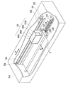
図1は、本発明が適用可能な液体吐出装置の一例として、インクジェット記録装置形態のものを示す概略斜視図である。液体吐出装置に挿入された記録媒体Pは、送りローラ107,108,109,110によって液体吐出ヘッドユニット100の記録可能領域へ搬送される。液体吐出ヘッドユニット100は、ガイド軸102によって、その延在方向に沿って移動可能に支持されている。そして、モータ103の駆動によってプーリ105,106に架けられたベルト104が移動し、これに伴って液体吐出ヘッドユニット100が記録領域をA方向に往復移動する。当該移動の過程で液体吐出を行うことが可能である。また、図において矢印Bで示す方向は記録媒体Pの搬送方向である。
1. FIG. 1 is a schematic perspective view showing an ink jet recording apparatus as an example of a liquid discharge apparatus to which the present invention can be applied. The recording medium P inserted into the liquid ejection device is conveyed to the recordable area of the liquid
液体吐出ヘッドユニット100には、複数色のインクを吐出するためのインクジェットヘッド形態の液体吐出ヘッド103と、それぞれの液体吐出ヘッド103にインクを供給するためのインクタンク101とが搭載されている。この例の液体吐出装置における複数色のインクは、ブラック(Bk)、シアン(C)、マゼンタ(M)、イエロー(Y)の4色である。なお、各色の位置は特に限定されるものではなく、また、用いる色調(色および濃度)の種類およびその数についても限定されるものではない。
The liquid
また、本例の場合、ブラック、シアン、マゼンタ、イエローの各色インク(Bk,C,M,Y)のインクタンクが全て独立に交換可能な構成となっている。液体吐出ヘッドユニット100には、Bk,C,M,Yの各色液滴を吐出する液体吐出ヘッドの群と、Bk用インクタンク101B、C用インクタンク101C、M用インクタンク101M、Y用インクタンク101Yが搭載される。各インクタンクは対応する液体吐出ヘッドと接続され、その液体吐出ヘッドの吐出口に連通する個別液室内にインクを供給する。この例以外にも、例えば、各色用のインクタンクと液体吐出ヘッドとが分離不能に一体となった構造としてもよい。また、液体吐出ヘッドユニットには液体吐出ヘッドのみを搭載し、装置の固定部位に設けたインクタンクから可撓性チューブ等を介してインクが供給されるものでもよい。これらの例以外にも、例えば、各色用のインクタンクを任意の組み合わせで一体構造としてもよい。
In the case of this example, the ink tanks of the respective color inks (Bk, C, M, Y) of black, cyan, magenta, and yellow are all replaceable independently. The liquid
液体吐出ヘッドユニット100が移動可能な主走査領域の一端(図では右端)の下部には、回復系ユニット112が配備されている。回復系ユニット112は、液体吐出ヘッドの吐出口形成面をキャッピングし、非記録動作時などにおいてはその保護を行ったり、あるいは吸引回復を行ったりするためのキャップや、吐出口形成面を払拭するワイパブレードなどを有したものとすることができる。
A
2.液体吐出ヘッド
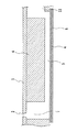
図2および図3は本発明に適用可能な液体吐出ヘッドの構成例であり、それぞれ、吐出口形成面側から見た模式的正面図およびそのC−C線断面図を示している。本実施形態で説明する液体吐出ヘッドは圧電素子の面外方向の歪を利用する所謂ベンダー型のヘッドである。
2. Liquid Discharge Head FIGS. 2 and 3 are configuration examples of a liquid discharge head applicable to the present invention, and show a schematic front view and a cross-sectional view taken along the line C-C as viewed from the discharge port forming surface side, respectively. . The liquid discharge head described in the present embodiment is a so-called bender type head that utilizes distortion in the out-of-plane direction of a piezoelectric element.
この例の液体吐出ヘッドは、インクを吐出する複数の吐出口2が設けられたオリフィスプレート1と、各吐出口に対応する個別液室3の複数およびこれらに共通に連通してインクを供給する共通液室11を画成する壁部が配置された基体6とを有する。個別液室3は、連通路7を介して吐出口2に連通している。
The liquid discharge head of this example supplies ink by communicating with an
個別液室3の側面の一部には変位可能な振動板4が設けられ、この振動板4に対して、個別液室の容積制御部である圧電素子(ピエゾ素子)および電極を含むアクチュエータ5が配置されている。圧電素子は、蒸着法,ゾル・ゲル法,CVD法,スパッタ法などによって成膜した圧電体薄膜であってもよい。アクチュエータ5に、記録情報に対応して駆動電圧信号を印加することにより振動板4を変位させ、個別液室3の容積変化を生じさせることで、吐出口2から液滴を吐出させることが可能である。アクチュエータ5は、これに印加される駆動電圧が下降する場合には個別液室の容積を増大させるよう、また駆動電圧が上昇する場合に個別液室の容積を減少させるよう、それぞれ厚み方向に変形するものとする。
A displaceable diaphragm 4 is provided on a part of the side surface of the individual liquid chamber 3, and an
なお、本発明を成すにあたって検討に使用した液体吐出ヘッドにおいて、吐出口2は直径30μmの円形状であり、吐出させる液体は、密度1.0×10³kg/m3、粘度2.0×10−3Pa・s、表面張力3.5×10−2N/mを持つインクとした。
In the liquid discharge head used in the study for forming the present invention, the
また、アクチュエータ5(上電極、圧電素子、下電極)、および振動板4はこれら自体の変形を容易にするために、振動板とアクチュエータとをあわせて10μmの厚みを持つ構成とした。圧電素子を圧電体薄膜として構成すればアクチュエータを薄く形成でき、この程度の厚みを実現できる。そして、この程度の薄膜形状であれば、個別液室の容積の増減を示す指標となる振動板変位の時間推移δ(t)は、アクチュエータ5の表面(上電極位置)の変位(面外変位)で表されているとみなすことができる。この変位は、振動板が形成されている面に対して垂直な方向の変位を指し、従って例えばレーザー・ドップラー方式によってその変位の測定を行うことで、振動板変位の時間推移ひいては個別液室3の体積変化(膨張、収縮)を知ることができる。
In addition, the actuator 5 (upper electrode, piezoelectric element, lower electrode) and the diaphragm 4 have a structure in which the diaphragm and the actuator are combined to have a thickness of 10 μm in order to facilitate deformation of the
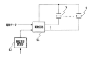
図4はアクチュエータ5を駆動するために用いられる駆動部の構成例を示す。アクチュエータ5は電力を供給するための電極配線を介して駆動回路51に接続されている。駆動回路51は、液体吐出情報(例えば記録情報)に対応する駆動データ(吐出の有無を定めるためのデータ)に応じ、制御部である駆動波形設定部53によって設定される駆動波形にて、アクチュエータ5を作動させることができる。
FIG. 4 shows a configuration example of a drive unit used for driving the
駆動波形設定部53は、好ましい液体吐出形態を生じさせる個別液室の容積増減の時間推移(振動板の面外変位の時間推移)が生じるような駆動波形を設定する。
The drive
3.比較例
ここで、本発明にあたって検討した例(比較例)について先に説明する。
3. Comparative Example Here, an example (comparative example) studied in the present invention will be described first.
図2および図3について説明したベンダー型の液体吐出ヘッドに対し、図4に示した駆動部を用いて、図5(a)に示す駆動信号を印加した。その際の振動板4の時間推移(振動板変位時刻歴線図)を図5(b)に示す。また、図6(a)〜(g)はこの際に観察された液滴の吐出状態を示す。図6を詳細に見ると、吐出口2側の液柱の付け根部が曲がっており、この影響で液滴の吐出方向の偏向(以下、「ヨレ」とも称する)が生じていることがわかる。
The drive signal shown in FIG. 5A was applied to the bender type liquid discharge head described with reference to FIGS. 2 and 3 using the drive unit shown in FIG. The time transition (diaphragm displacement time history diagram) of the diaphragm 4 at that time is shown in FIG. 6A to 6G show the droplet discharge state observed at this time. When FIG. 6 is seen in detail, it can be seen that the base of the liquid column on the
本発明者は、このヨレの発生の要因を鋭意検討した。まず、図5の(a)と(b)との比較から明らかなように、ベンダー型の液体吐出ヘッドの場合、電圧変化と振動板4の変位とが必ずしもそのまま一致する訳ではない。従って、駆動信号だけでなく、振動板変位時刻歴線図を基に要因分析することとした。 The inventor diligently investigated the cause of this twist. First, as is clear from a comparison between FIGS. 5A and 5B, in the case of a bender type liquid discharge head, the voltage change and the displacement of the diaphragm 4 do not always coincide with each other. Therefore, the factor analysis is performed based on not only the drive signal but also the diaphragm displacement time history diagram.
図5(b)の横軸は時間、縦軸は振動板の変位であって、変位量が増加する方向への推移は個別液室3を膨張させることを示している。また、図5(b)においてtBは吐出口側にて液柱の分断が観察される時点を示し、区間Tは図5(a)の駆動信号入力完了後に出現する振動板の極小変位点δL出現の時点から液柱の分断が観察される時点tBまでの時間を示す。 In FIG. 5B, the horizontal axis represents time and the vertical axis represents the displacement of the diaphragm, and the transition in the direction in which the amount of displacement increases indicates that the individual liquid chamber 3 is expanded. Further, in FIG. 5B, t B indicates a point in time when the liquid column is observed to be divided on the discharge port side, and a section T indicates the minimum displacement point of the diaphragm that appears after the completion of the drive signal input in FIG. It shows the time from the [delta] L emergence to time t B that dividing of the liquid column is observed.
上記方針に基づいて吐出過程を分析すると、以下のようになる。 The discharge process is analyzed based on the above policy as follows.
第一の信号波形部分P1によって、個別液室3を膨張させる方向に振動板4を変位させて(図5の(a)における振動板変位時刻歴線C1)、図6(a)のようにメニスカスを吐出口内に引き込む。次に第二の信号波形部分P2によって、個別液室3を収縮させる方向に振動板4を変位させて(図5の(a)における振動板変位時刻歴線C2)、図6(b)のようにメニスカスを盛り上げ、液柱を形成する。 The diaphragm 4 is displaced in the direction in which the individual liquid chamber 3 is expanded by the first signal waveform portion P1 (the diaphragm displacement time history line C1 in FIG. 5A), as shown in FIG. 6A. Pull the meniscus into the outlet. Next, the diaphragm 4 is displaced in the direction in which the individual liquid chamber 3 is contracted by the second signal waveform portion P2 (diaphragm displacement time history line C2 in FIG. 5A), and FIG. In this way, the meniscus is raised to form a liquid column.
次に第三の信号波形部分P3によって、個別液室3を再膨張させる方向に振動板4を変位させて(図5の(a)における振動板変位時刻歴線C3)、メニスカスを吐出口内に引き込み、図6(c)のように突出液柱の太さのリサイズ(調整)を行う。次に第四の信号波形部分P4により個別液室3を収縮させる方向に振動板4を変位させて(図5の(a)における振動板変位時刻歴線C4)、個別液室の容積を初期状態にするために初期待機電圧V1に復帰させる。第四の信号P4入力完了後の吐出状態が図6(d)であり、この図に示すように主駆動信号入力完了後も液柱は千切れない。 Next, the diaphragm 4 is displaced in the direction in which the individual liquid chamber 3 is re-expanded by the third signal waveform portion P3 (the diaphragm displacement time history line C3 in FIG. 5A), and the meniscus is placed in the discharge port. Pulling in and resizing (adjusting) the thickness of the protruding liquid column as shown in FIG. Next, the diaphragm 4 is displaced in the direction in which the individual liquid chamber 3 is contracted by the fourth signal waveform portion P4 (the diaphragm displacement time history line C4 in FIG. 5A), and the volume of the individual liquid chamber is initially set. To return to the initial state, the initial standby voltage V1 is restored. The discharge state after completion of the fourth signal P4 input is shown in FIG. 6D, and the liquid column does not break even after the main drive signal input is completed as shown in FIG.
図5(b)の振動板変位時刻歴線図において、第四の信号波形部分P4の入力完了後、インクとの連成挙動によって生じる個別液室3の内容積変動に伴って振動板の変位が極小となる極小変位点δLが出現し、次に極大となる振動板変位点が出現する。この極大変位点出現後、個別液室3を収縮させる方向に変位させると、時点tCで振動板変位が極小変位点δLを下回った。これに対応して、図6(e)に示すように液柱の付け根にはメニスカスのオーバーシュートが発生し、液柱の付け根が屈曲させられて、図6(f)および(g)のように液滴のヨレが生じたと考えられる。 In the diaphragm displacement time history diagram of FIG. 5B, the displacement of the diaphragm is accompanied by the change in the internal volume of the individual liquid chamber 3 caused by the coupled behavior with ink after the completion of the input of the fourth signal waveform portion P4. There appeared the minimum displacement point [delta] L of the minimum, the diaphragm displacement point next becomes maximum appears. After the maximum displacement point occurrence and is displaced in a direction to contract the individual liquid chamber 3, the diaphragm displacement at time t C falls below the minimum displacement point [delta] L. Correspondingly, as shown in FIG. 6 (e), a meniscus overshoot occurs at the base of the liquid column, and the base of the liquid column is bent, as shown in FIGS. 6 (f) and 6 (g). It is probable that the droplet was twisted.
4.実施例
そこで本発明者らは、外界から吐出口部を観察することによって、吐出口から突出した液柱が千切れる前にメニスカスのオーバーシュートが発生しないように制御することで、液滴のヨレを防止できるのではないかと考察した。
4). Embodiments Accordingly, the present inventors have observed the discharge port portion from the outside to control the occurrence of liquid droplets by controlling so that meniscus overshoot does not occur before the liquid column protruding from the discharge port is broken. I thought that it could be prevented.
ここで、本発明が有効に適用される構成をまとめると、次のとおりである。 Here, the configuration to which the present invention is effectively applied is summarized as follows.
液体吐出ヘッドは、液体(インク等)を吐出する吐出口と、この吐出口と連通する個別液室と、その個別液室の内側面の一部を形成している振動板と、その振動板をアクチュエータにより変形させ、個別液室の容積を変化させることで液体を吐出させるものである。ここで、当該吐出を行わせるためにアクチュエータに印加される主駆動信号の波形は、個別液室を膨張させるための波形部分と、個別液室を収縮させるための波形部分と、個別液室を再膨張させるための波形部分と、個別液室を収縮させるための波形部分とを含む。また、主駆動信号の入力完了後には振動板の変位が極小となる極小変位点δLが出現する。 The liquid ejection head includes an ejection port that ejects liquid (ink, etc.), an individual liquid chamber that communicates with the ejection port, a diaphragm that forms part of the inner surface of the individual liquid chamber, and the diaphragm Is deformed by an actuator, and the volume of the individual liquid chamber is changed to discharge the liquid. Here, the waveform of the main drive signal applied to the actuator to perform the discharge includes a waveform portion for expanding the individual liquid chamber, a waveform portion for contracting the individual liquid chamber, and an individual liquid chamber. A corrugated portion for reinflation and a corrugated portion for contracting the individual liquid chamber are included. Further, after completing the input of the main drive signal minimum displacement point [delta] L of the displacement of the vibration plate is minimum appears.
そして本発明の特徴構成では、主駆動信号の入力後に、次のような補助駆動信号を入力する。すなわち、振動板変位時刻歴線にて、極小変位点δLが出現した後、吐出口側にて液柱分断が観察される時間tBまでの振動板変位が極小変位点δLを下回らないように個別液室を膨張させる波形部分と、初期待機電圧に戻す波形部分とを含む補助駆動信号である。 In the characteristic configuration of the present invention, the following auxiliary drive signal is input after the main drive signal is input. That is, after the minimal displacement point δ L appears on the diaphragm displacement time history line, the diaphragm displacement until time t B when the liquid column division is observed on the discharge port side does not fall below the minimal displacement point δ L. Thus, the auxiliary drive signal includes a waveform portion for expanding the individual liquid chamber and a waveform portion for returning to the initial standby voltage.
本発明者らは、かかる補助駆動信号を用いれば確実に所期の効果が得られると考察し、下記実施例に基いてその検証を行った。 The present inventors considered that the desired effect can be surely obtained by using such an auxiliary drive signal, and verified the result based on the following examples.
実施例1
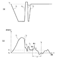
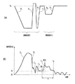
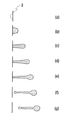
図2および図3について説明した液体吐出ヘッドに対し、図4に示した駆動部を用いて、図7(a)に示す駆動信号を印加した。その際の振動板4の変位時刻歴線図を図7(b)に示す。図5(b)と同様、図7(b)において横軸は時間、縦軸は振動板の変位を示し、変位量が増加する方向への推移は個別液室3を膨張させることを示している。また、図5(a)の時間tBは液柱の切断部が観察された時点を示す。図8(a)〜(f)は観察された液滴の吐出状態である。
Example 1
A drive signal shown in FIG. 7A is applied to the liquid ejection head described with reference to FIGS. 2 and 3 using the drive unit shown in FIG. FIG. 7B shows a displacement time history diagram of the diaphragm 4 at that time. As in FIG. 5B, in FIG. 7B, the horizontal axis indicates time, the vertical axis indicates the displacement of the diaphragm, and the transition in the direction in which the amount of displacement increases indicates that the individual liquid chamber 3 is expanded. Yes. The time t B of FIG. 5 (a) shows the time when the cutting portion of the liquid column was observed. FIGS. 8A to 8F show the observed droplet discharge state.
図7(a)において、第一の波形部分P1から第四の波形部分P4が主駆動信号の波形を形成している。本実施例の場合、第一の波形部分P1〜第四の波形部分P4は比較例と同一とした。従って、主駆動信号入力完了までの吐出過程は比較例と同様であり、個別液室3を膨張、収縮、再膨張および再収縮させることによって、図8(a)〜(d)に示すように液柱が形成される。主駆動信号入力完了後の吐出状態が図8(d)であり、この図に示すように主駆動信号入力完了後も液柱は千切れない。 In FIG. 7A, the first waveform portion P1 to the fourth waveform portion P4 form the waveform of the main drive signal. In this embodiment, the first waveform portion P1 to the fourth waveform portion P4 are the same as those in the comparative example. Accordingly, the discharge process up to the completion of the main drive signal input is the same as in the comparative example, and the individual liquid chamber 3 is expanded, contracted, re-expanded and re-contracted, as shown in FIGS. A liquid column is formed. The discharge state after the completion of the main drive signal input is shown in FIG. 8D. As shown in this figure, the liquid column is not broken even after the completion of the main drive signal input.
なお、主駆動信号の第二の波形部分P2および第三の波形部分P3の電圧は初期待機電圧V1と同一でも構わない。また、各波形部分の電圧や印加時間を変えることで振動板変位を適切に調整し、所望の吐出性能(吐出量Vd,吐出速度v)が得られるように設定することができる。 Note that the voltages of the second waveform portion P2 and the third waveform portion P3 of the main drive signal may be the same as the initial standby voltage V1. In addition, it is possible to appropriately adjust the diaphragm displacement by changing the voltage of each waveform portion and the application time so that desired discharge performance (discharge amount Vd, discharge speed v) can be obtained.
さて、主駆動信号入力を完了した後、振動板4はインクとの連成挙動によって振動板の極小変位点δLが出現し、次に個別液室3を膨張させる方向に振動板4が変位する。 Now, after the main drive signal input is completed, the diaphragm 4 has a minimum displacement point δ L of the diaphragm due to the coupled behavior with the ink, and then the diaphragm 4 is displaced in the direction in which the individual liquid chamber 3 is expanded. To do.
ここで本実施例においては、主駆動信号入力完了後に、補助駆動信号を入力する。図7(a)の第五の波形部分P5および第六の波形部分P6を含むものが補助駆動信号である。極小変位点δLが出現した後、この補助駆動信号に含まれる第五の波形部分P5によって個別液室3を膨張させる方向に振動板4を変位させ(図7(b)の振動板変位時刻歴線C5)、個別液室3を収縮させる方向への振動板変位を抑制した(図8(e))。そして、最後に第六の波形部分P6によって個別液室を初期容積に戻すための初期待機電圧V1に復帰させた。 Here, in this embodiment, the auxiliary drive signal is input after the main drive signal input is completed. The auxiliary drive signal includes the fifth waveform portion P5 and the sixth waveform portion P6 in FIG. After minimum displacement point [delta] L is encountered, the diaphragm displacement time of the fifth waveform portion P5 contained in the auxiliary drive signal to displace the vibrating plate 4 in the direction of expanding the individual liquid chamber 3 (FIG. 7 (b) History line C5), diaphragm displacement in the direction of contracting the individual liquid chamber 3 was suppressed (FIG. 8E). Finally, the sixth waveform portion P6 returns the individual liquid chamber to the initial standby voltage V1 for returning to the initial volume.
以上のような補助駆動信号を入力した結果、図8(f)に示すようにメニスカスのオーバーシュートが発生する前に液柱の切断部が観察され、液柱には屈曲が見られず、図8(g)に示すようにヨレのない吐出が実現できた。 As a result of inputting the auxiliary drive signal as described above, a cut portion of the liquid column is observed before the meniscus overshoot occurs as shown in FIG. 8F, and the liquid column is not bent. As shown in FIG. 8 (g), discharge without deviation was realized.
実施例2
実施例2においては、主駆動信号は実施例1と同一とし、その後に入力する補助駆動信号の第6の波形部分P6を、積極的に液柱の切断部が観察されてから入力するように変更した。このように変更を行っても、実施例1と同様に、図8(f)に示すようにメニスカスのオーバーシュートが発生する前に液柱の切断部が観察され、液柱には屈曲が見られず、図8(g)に示すようにヨレのない吐出が実現できた。
Example 2
In the second embodiment, the main drive signal is the same as that of the first embodiment, and the sixth waveform portion P6 of the auxiliary drive signal that is input thereafter is input after the liquid column cutting portion is positively observed. changed. Even if such a change is made, as in Example 1, as shown in FIG. 8 (f), the cut portion of the liquid column is observed before the meniscus overshoot occurs, and the liquid column is bent. As shown in FIG. 8 (g), discharge without deviation was realized.
5.その他
なお、上述した各種の数値は、例示であることは勿論である。
5). Others Of course, the various numerical values described above are merely examples.
また、上例ではインクジェット記録装置形態の液体吐出装置およびヘッドに本発明を適用した場合について説明したが、本発明は、記録装置だけでなくパターニング装置や塗布装置など様々な液体吐出装置に好ましく適用可能である。装置に応じて様々な物性の液体や様々なヘッド構造が用いられることに対して、吐出口を小径化せずに吐出液滴の微細化を達成し得る適切かつ普遍的な液体吐出ヘッドの駆動制御の指針を与えることができるからである。 In the above example, the case where the present invention is applied to the liquid ejecting apparatus and the head in the form of an ink jet recording apparatus has been described. However, the present invention is preferably applied not only to the recording apparatus but also to various liquid ejecting apparatuses such as a patterning apparatus and a coating apparatus. Is possible. Suitable and universal liquid ejection head drive that can achieve finer ejection droplets without reducing the diameter of the ejection port, as liquids with various physical properties and various head structures are used depending on the device This is because a control guideline can be given.
さらに、上記実施形態においてはアクチュエータ5に正の駆動電圧を与えることにより個別液室3が収縮する形態について説明したが、負の駆動電圧を与えることにより個別液室3が収縮する形態にも本発明が適用可能であることは言うまでもない。
Further, in the above-described embodiment, the form in which the individual liquid chamber 3 contracts by applying a positive drive voltage to the
2 吐出口
3 個別液室
4 振動板
5 アクチュエータ
2 Discharge port 3 Individual liquid chamber 4
Claims (5)
前記液体の吐出を行わせるために、前記個別液室を膨張させるための波形部分と、前記個別液室を収縮させるための波形部分と、前記個別液室を再膨張させるための波形部分と、前記個別液室を収縮させるための波形部分とを含む主駆動信号を前記アクチュエータに入力し、
当該主駆動信号の入力完了後に出現する前記振動板の極小変位点δLに対し、当該出現の後、吐出口側にて液柱分断が観察される時間tBまでの振動板変位が極小変位点δLを下回らないように個別液室を膨張させるための波形部分と、前記個別液室の容積を収縮させて初期状態に戻すための波形部分とを含む補助駆動信号を前記アクチュエータに入力する、
ことを特徴とする液体吐出方法。 A discharge port for discharging liquid, an individual liquid chamber communicating with the discharge port, a diaphragm that forms part of the inner surface of the individual liquid chamber, and a volume of the individual liquid chamber by deforming the diaphragm And a liquid ejecting method for ejecting a liquid by changing the volume of the individual liquid chamber.
A corrugated portion for expanding the individual liquid chamber, a corrugated portion for contracting the individual liquid chamber, and a corrugated portion for reexpanding the individual liquid chamber in order to cause the liquid to be discharged; A main drive signal including a waveform portion for contracting the individual liquid chamber is input to the actuator;
With respect to the minimum displacement point δ L of the diaphragm that appears after completion of the input of the main drive signal, the diaphragm displacement until the time t B at which the liquid column division is observed on the discharge port side after the appearance is minimal displacement. inputting a waveform portion for inflating the individual liquid chamber so as not to fall below the point [delta] L, an auxiliary drive signal including a waveform portion for the return to contract the volume of the individual liquid chamber initial state to the actuator ,
A liquid discharge method characterized by the above.
前記アクチュエータに主駆動信号を入力し、当該入力後に補助駆動信号を入力する制御部を具え、
前記主駆動信号は、前記液体の吐出を行わせるために、前記個別液室を膨張させるための波形部分と、前記個別液室を収縮させるための波形部分と、前記個別液室を再膨張させるための波形部分と、前記個別液室を収縮させるための波形部分とを含み、
前記補助駆動信号は、前記主駆動信号の入力完了後に出現する前記振動板の極小変位点δLに対し、当該出現の後、吐出口側にて液柱分断が観察される時間tBまでの振動板変位が極小変位点δLを下回らないように個別液室を膨張させるための波形部分と、前記個別液室の容積を収縮させて初期状態に戻すための波形部分とを含む、
ことを特徴とする液体吐出装置。 A discharge port for discharging liquid, an individual liquid chamber communicating with the discharge port, a diaphragm that forms part of the inner surface of the individual liquid chamber, and a volume of the individual liquid chamber by deforming the diaphragm In a liquid ejection apparatus that ejects liquid by a volume change of the individual liquid chamber, using a liquid ejection head that includes an actuator to be changed,
A main drive signal is input to the actuator, and a controller that inputs an auxiliary drive signal after the input is provided.
The main drive signal includes a waveform portion for expanding the individual liquid chamber, a waveform portion for contracting the individual liquid chamber, and a re-expansion of the individual liquid chamber in order to cause the liquid to be discharged. And a corrugated portion for contracting the individual liquid chamber,
Said auxiliary drive signal to the minimum displacement point [delta] L of the diaphragm appearing after completion of input of the main drive signal, after the occurrence of at the discharge port side to the time t B that the liquid column interrupted is observed including a corrugated portion for inflating the individual liquid chamber so that the vibration plate displacement does not fall below the minimum displacement point [delta] L, and a waveform portion for the contract the volume of the individual liquid chamber back into an initial state,
A liquid discharge apparatus characterized by the above.
Priority Applications (1)
| Application Number | Priority Date | Filing Date | Title |
|---|---|---|---|
| JP2008322396A JP2010143065A (en) | 2008-12-18 | 2008-12-18 | Liquid discharge method and liquid discharge device |
Applications Claiming Priority (1)
| Application Number | Priority Date | Filing Date | Title |
|---|---|---|---|
| JP2008322396A JP2010143065A (en) | 2008-12-18 | 2008-12-18 | Liquid discharge method and liquid discharge device |
Publications (1)
| Publication Number | Publication Date |
|---|---|
| JP2010143065A true JP2010143065A (en) | 2010-07-01 |
Family
ID=42563995
Family Applications (1)
| Application Number | Title | Priority Date | Filing Date |
|---|---|---|---|
| JP2008322396A Pending JP2010143065A (en) | 2008-12-18 | 2008-12-18 | Liquid discharge method and liquid discharge device |
Country Status (1)
| Country | Link |
|---|---|
| JP (1) | JP2010143065A (en) |
Cited By (1)
| Publication number | Priority date | Publication date | Assignee | Title |
|---|---|---|---|---|
| JP2017052153A (en) * | 2015-09-08 | 2017-03-16 | 株式会社リコー | Device for ejecting liquid, drive waveform generation device, and head drive method |
-
2008
- 2008-12-18 JP JP2008322396A patent/JP2010143065A/en active Pending
Cited By (1)
| Publication number | Priority date | Publication date | Assignee | Title |
|---|---|---|---|---|
| JP2017052153A (en) * | 2015-09-08 | 2017-03-16 | 株式会社リコー | Device for ejecting liquid, drive waveform generation device, and head drive method |
Similar Documents
| Publication | Publication Date | Title |
|---|---|---|
| US9067414B2 (en) | Liquid ejection head and method of driving the same | |
| JP2015096322A (en) | Printing device, inkjet head, and printing method | |
| JP6819050B2 (en) | Liquid discharge device, control method of liquid discharge device, and device driver | |
| US8449056B2 (en) | Driving method of liquid discharge head and liquid discharge apparatus | |
| JP5459695B2 (en) | Inkjet recording apparatus and inkjet recording method | |
| JP5905806B2 (en) | Method for driving liquid discharge head and image forming apparatus | |
| US9259923B2 (en) | Method of driving liquid ejection head and liquid ejection apparatus | |
| US8721053B2 (en) | Liquid droplet discharge head and image forming apparatus including same | |
| US12059895B2 (en) | Liquid discharging head | |
| JP2010503555A (en) | Fluid ejection device | |
| JP2010143065A (en) | Liquid discharge method and liquid discharge device | |
| US11919301B2 (en) | Liquid ejecting apparatus | |
| EP2342081B1 (en) | Electrostatic liquid-ejection actuation mechanism | |
| JP7377052B2 (en) | Liquid ejector and inkjet printer | |
| JP2005169963A (en) | Liquid discharge method and apparatus | |
| JP2008168531A (en) | Liquid ejection method and liquid ejection apparatus | |
| JP2008168533A (en) | Liquid ejection method and liquid ejection apparatus | |
| JP2008168532A (en) | Liquid ejection method and liquid ejection apparatus | |
| US20240359462A1 (en) | Liquid droplet ejecting head | |
| US12558894B2 (en) | Liquid droplet ejecting head | |
| US12508815B2 (en) | Liquid droplet discharging apparatus | |
| JP2015080945A (en) | Inkjet device and inkjet method | |
| JP2008173920A (en) | Liquid ejector | |
| JPH0976513A (en) | Ink jet device | |
| JP2007203664A (en) | Liquid ejection method and apparatus |
Legal Events
| Date | Code | Title | Description |
|---|---|---|---|
| RD02 | Notification of acceptance of power of attorney |
Free format text: JAPANESE INTERMEDIATE CODE: A7422 Effective date: 20101106 |