JP2010143300A - Conveying-out position adjustment system for landing conveyor - Google Patents
Conveying-out position adjustment system for landing conveyor Download PDFInfo
- Publication number
- JP2010143300A JP2010143300A JP2008320422A JP2008320422A JP2010143300A JP 2010143300 A JP2010143300 A JP 2010143300A JP 2008320422 A JP2008320422 A JP 2008320422A JP 2008320422 A JP2008320422 A JP 2008320422A JP 2010143300 A JP2010143300 A JP 2010143300A
- Authority
- JP
- Japan
- Prior art keywords
- conveyor
- landing
- expansion
- landing conveyor
- hull
- Prior art date
- Legal status (The legal status is an assumption and is not a legal conclusion. Google has not performed a legal analysis and makes no representation as to the accuracy of the status listed.)
- Pending
Links
- 230000008602 contraction Effects 0.000 claims abstract description 20
- 238000005259 measurement Methods 0.000 claims abstract description 7
- 239000013590 bulk material Substances 0.000 abstract description 11
- 238000006073 displacement reaction Methods 0.000 abstract 1
- 238000004873 anchoring Methods 0.000 description 6
- 230000007423 decrease Effects 0.000 description 4
- XEEYBQQBJWHFJM-UHFFFAOYSA-N Iron Chemical compound [Fe] XEEYBQQBJWHFJM-UHFFFAOYSA-N 0.000 description 2
- 239000000428 dust Substances 0.000 description 2
- XLYOFNOQVPJJNP-UHFFFAOYSA-N water Substances O XLYOFNOQVPJJNP-UHFFFAOYSA-N 0.000 description 2
- 235000019738 Limestone Nutrition 0.000 description 1
- 235000004789 Rosa xanthina Nutrition 0.000 description 1
- 241000109329 Rosa xanthina Species 0.000 description 1
- 239000003245 coal Substances 0.000 description 1
- 229910052742 iron Inorganic materials 0.000 description 1
- 239000006028 limestone Substances 0.000 description 1
- 238000000034 method Methods 0.000 description 1
- 230000000630 rising effect Effects 0.000 description 1
- 230000004580 weight loss Effects 0.000 description 1
- 239000002023 wood Substances 0.000 description 1
Images
Landscapes
- Ship Loading And Unloading (AREA)
Abstract
【課題】ばら物運搬船からセルフアンローディングシステムによりばら物を陸揚げする場合に埠頭に配置した搬入ホッパの中央位置に合わせた船体から突設した陸揚げコンベアの搬出端のずれを調整する。
【解決手段】陸揚げコンベア3がシャトルコンベアであって、その陸揚げコンベヤ3の搬出端31に備えた搬入ホッパ6との間の距離を測定するための伸縮方向位置センサー8と、この伸縮方向位置センサー8からの測定信号により陸揚げコンベア3の伸縮機構33を制御して陸揚げコンベアを伸縮させる制御装置9とからなる陸揚げコンベア伸縮装置10を備えた。
【選択図】図1Displacement of an unloading end of a landing conveyor protruding from a hull aligned with a central position of a loading hopper arranged on a wharf when a bulk material is unloaded from a bulk carrier by a self-unloading system is adjusted.
A landing conveyor 3 is a shuttle conveyor, and an expansion / contraction direction position sensor 8 for measuring a distance from a loading hopper 6 provided at a discharge end 31 of the landing conveyor 3 and the expansion / contraction direction position sensor. 8 is provided with a landing conveyor expansion / contraction device 10 including a control device 9 that controls the expansion / contraction mechanism 33 of the landing conveyor 3 by a measurement signal from 8 to expand and contract the landing conveyor.
[Selection] Figure 1
Description
本発明は、例えば石炭、鉄鉱石、ウッドチップ、石灰石、穀物などのばら物を運搬する運搬船、特に、セルフアンローディングシステムを備えたばら物運搬船の陸揚げ時における船体の埠頭に対する位置を調整するシステムに関するものであり、詳しくは、陸揚げ時において、船体に備えたばら物搬出に用いるシャトルコンベアからなる陸揚げコンベアの搬出端が埠頭側に備えた搬入ホッパに近接して位置するように調整するシステムに関するものである。 The present invention relates to a system for adjusting the position of a hull with respect to a wharf when landing a bulk carrier carrying a bulk material such as coal, iron ore, wood chips, limestone, and grains, in particular, a bulk material carrier equipped with a self-unloading system. More particularly, the present invention relates to a system that adjusts so that the unloading end of the landing conveyor, which is a shuttle conveyor used for unloading the bulk material provided on the hull, is positioned close to the loading hopper provided on the wharf side when landing. Is.
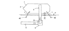
従来、セルフアンローディングシステムを備えたばら物運搬船が知られており、このようなばら物運搬船では搬送先の埠頭などに着いた際に、図2に示すように、ばら物運搬船1の船体2に備えられた陸揚げコンベア3の搬出端31を、埠頭4側に備えた搬送コンベア5への搬入ホッパ6に合致させて船内に貯留したばら物を陸揚げするが、ばら物運搬船1は陸揚げ時には、ばら物を陸揚げする埠頭4に所定の間隔を隔てて配置された一対の繋留柱42,42に張架させた繋留ロープ7,7により繋留するのが一般的であるが、潮位の変化や積荷の減少により船体2と埠頭4との間の高さ位置が変化して前記繋留ロープ7,7が弛むと船体2と埠頭4との距離が変化するので船体2に備えられた陸揚げコンベア3の搬出端31と埠頭4側に備えた搬送コンベア5への搬入ホッパ6との距離が変化することになり、運搬物であるばら物が作業ステージ41上にこぼれたり粉塵が飛散する等の問題が生じることになる。
Conventionally, a bulk carrier equipped with a self-unloading system is known. When such a bulk carrier arrives at a wharf or the like of a transport destination, as shown in FIG. 2, the hull 2 of the bulk carrier 1 is shown. The unloading
一方、例えば特開2005−88835号公報などに提示されているように、従来から船体内にバラストタンクを備えることによりに喫水を保って航海中の船の安定を計ることが行われているが、これらは積荷による船体の偏りや自重の軽減に伴う船体の偏りを解消するものであり、主として航海前に所定の調製をするものであることから、殆どが作業員が手動により調製するものであり、本発明のような短時間の内に刻々と変化する船体の昇降には対処できないものであった。 On the other hand, for example, as disclosed in Japanese Patent Application Laid-Open No. 2005-88835 and the like, conventionally, by providing a ballast tank in the hull, it is possible to keep the draft and measure the stability of the ship during voyage. These are intended to eliminate the deviation of the hull due to cargo and the deviation of the hull accompanying the reduction of its own weight, and are mainly prepared manually before voyage. In other words, it is impossible to cope with the rising and lowering of the hull which changes every moment within a short time as in the present invention.
また、特公平7−98513号公報や特開平10−236385号公報等には積荷を陸揚げする際にバラストタンクにより船体を水平に保つ技術が開示されているが、これらは例えば測定した各バラストタンクの水位をもとに積荷の位置などを加味して演算して給排水量を制御するなどきわめて複雑な機構と面倒な制御手段とが必要であるばかりか、対象となる積荷が大重量物であって、潮位の変化や積荷のばら物の減少による比較的長時間にわたって徐々に変位する船体の変化に対応することができないものであった。
本発明は前記従来の問題点であるばら物運搬船からセルフアンローディングシステムによりばら物を陸揚げする場合に潮位の変化や積載物の減少による埠頭と船体との間隔が変化しても搬入ホッパの中央に合わせた船体から突設したシャトルコンベアである陸揚げコンベアの搬出端がずれることなくばら物がこぼれたり粉塵が飛散するという問題点を解決することを課題とするものである。 In the present invention, when a bulk material is unloaded from a bulk carrier by the self-unloading system, the center of the loading hopper is changed even if the gap between the wharf and the hull is changed due to a change in tide level or a decrease in the load. It is an object of the present invention to solve the problem that loose matters are spilled or dust is scattered without shifting the unloading end of a landing conveyor that is a shuttle conveyor protruding from a hull matched to the hull.
前記課題を解決するためになされた本発明は、ばら物運搬船に装備されるセルフアンローディングシステムにおいて積載したばら物を埠頭側に備えた搬入ホッパに搬出する陸揚げコンベアの搬出位置調整手段において、前記陸揚げコンベアがシャトルコンベアであって、その陸揚げコンベヤの搬出端に備えた前記搬入ホッパとの間の距離を測定するための伸縮方向位置センサーと、この伸縮方向位置センサーからの測定信号により前記陸揚げコンベアの伸縮機構を制御して前記陸揚げコンベアを伸縮させる制御装置とからなる陸揚げコンベア伸縮装置を備えたこととした。 The present invention, which has been made to solve the above-mentioned problems, is the unloading position adjusting means of the landing conveyor for unloading the bulk material loaded in the self-unloading system equipped on the bulk carrier to the loading hopper provided on the wharf side. The landing conveyor is a shuttle conveyor, and an extension direction position sensor for measuring the distance between the loading hopper provided at the unloading end of the landing conveyor, and the landing conveyor by a measurement signal from the extension direction position sensor A landing conveyor expansion / contraction device comprising a control device for controlling the expansion / contraction mechanism to extend and contract the landing conveyor is provided.
シャトルコンベアである陸揚げコンベヤの搬出端に備えた前記搬入ホッパとの間の距離を測定するための伸縮方向位置センサーと、この伸縮方向位置センサーからの測定信号により前記陸揚げコンベアの伸縮機構を制御して前記陸揚げコンベアを伸縮させることにより搬出端の位置を調節して搬入ホッパの中央に合わせた前記搬出端がずれることを防止する。 The expansion / contraction direction position sensor for measuring the distance to the carry-in hopper provided at the carry-out end of the landing conveyor, which is a shuttle conveyor, and the expansion / contraction mechanism of the landing conveyor are controlled by a measurement signal from the expansion / contraction direction position sensor. Thus, the position of the unloading end is adjusted by expanding and contracting the landing conveyor to prevent the unloading end aligned with the center of the loading hopper from shifting.
本発明である陸揚げコンベアの位置調整システムによれば、ばら物運搬船に装備されるセルフアンローディングシステムにより陸揚げする際に、シャトルコンベアである陸揚げコンベアの搬出端を埠頭に配置した搬入ホッパの中央に合わせて陸揚げを開始するだけで、ばら物運搬船が潮位の変化や波浪、更には、船体自身の陸揚げに伴う重量減による喫水変化などにより船体と埠頭との距離が変化したとしても陸揚げコンベアの搬出端と搬入ホッパとの間隔が拡がることなく陸揚げを続けることができる。 According to the landing conveyor position adjustment system of the present invention, when landing by a self-unloading system equipped on a bulk carrier, the unloading end of the landing conveyor, which is a shuttle conveyor, is placed in the center of the loading hopper arranged at the wharf. Just by starting landing at the same time, the bulk carrier can carry out the landing conveyor even if the distance between the hull and the wharf changes due to changes in tide level, waves, and draft changes due to weight loss accompanying the landing of the hull itself. Landing can be continued without increasing the distance between the end and the carry-in hopper.
次に本発明の最良の形態について図面を参照して説明する。 Next, the best mode of the present invention will be described with reference to the drawings.
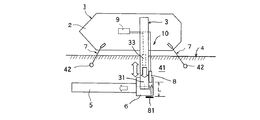
図1は本発明の好ましい実施の形態における側面概略を示すものであり、本実施の形態に用いられるばら物運搬船1は船体2に例えば運搬するばら物の貨物室並びに貨物室に貯蔵したばら物をブームコンベアにより形成される陸揚げコンベア3から埠頭4に設置した陸側コンベア5の基端に配置した搬入ホッパ6へ自動的に搬出するセルフアンローディングシステム(図示せず)を備えている。
FIG. 1 shows a schematic side view of a preferred embodiment of the present invention. A bulk carrier 1 used in the present embodiment is a bulk room for bulk material to be transported to a hull 2, for example, and bulk material stored in a cargo room. Is provided with a self-unloading system (not shown) that automatically unloads from a
船体2はその船首及び船尾において、ばら物を陸揚げする埠頭4の作業ステージ41に所定の間隔を隔てて配置された一対の繋留柱42,42に張架した繋留ロープ7,7により所定位置に繋留されている。
The hull 2 is placed at a predetermined position at the bow and stern by anchoring ropes 7 and 7 stretched between a pair of anchoring
そして、船体2に配置される陸揚げコンベア3が長さ方向に伸縮可能なシャトルコンベアにより形成され、その搬出端31に、搬入ホッパ6との間の距離を測定するための伸縮方向位置センサー8と、この伸縮方向位置センサー8からの測定信号により陸揚げコンベア3に装備された伸縮機構33を制御して陸揚げコンベア3を伸縮させる制御装置9とからなる陸揚げコンベア伸縮装置10を備えている。特に、本実施の形態では、伸縮方向位置センサー8はその対向面に配置されたターゲット81との間の距離Lを測定してその測定信号が前記制御装置9に送信される。
The
従って、本実施の形態によれば、陸揚げの開始時における陸揚げコンベア3の搬出端31が排出ホッパ6の中央部に合致して調製し、このときの搬出端31の排出ホッパ6に配置したターゲット81との間の距離Lを測定して制御装置9に送信した測定信号を基準隙間値として記憶しておき、陸揚げを継続して行っている際に、潮位の変化が生じたり積荷の減少等により船体2と埠頭4との距離が変化して伸縮方向位置センサー8と排出ホッパ6との距離Lが拡がって搬出端31とホッパ6との間隔が拡がると伸縮方向位置センサー8からの信号が制御装置9に送られて、伸縮機構33により陸揚げコンベア3が伸縮して伸縮方向位置センサー8とターゲット81との間の距離Lが元の前記基準隙間値に復帰するので陸揚げ作業中は陸揚げコンベア3の排出端31が船体2の幅方向については常に排出ホッパ6の中央部に位置することになる。
Therefore, according to the present embodiment, the carry-out
1 ばら物運搬船、2 船体、3 陸揚げコンベア、4 埠頭、6 搬入ホッパ、7 繋留装置、8 伸縮位置センサー、9 制御装置、33 伸縮機構
1 Bulk carrier, 2 hull, 3 landing conveyor, 4 wharf, 6 loading hopper, 7 anchoring device, 8 telescopic position sensor, 9 control device, 33 telescopic mechanism
Claims (1)
In the unloading position adjustment means of the landing conveyor for unloading the bulk loaded in the self-unloading system equipped on the bulk carrier to the loading hopper provided on the wharf side, the landing conveyor is a shuttle conveyor, and the landing conveyor An expansion / contraction direction position sensor for measuring a distance between the carry-in end and the carry-in hopper, and a measurement signal from the expansion / contraction direction position sensor controls an expansion / contraction mechanism of the landing conveyor to expand / contract the landing conveyor. A landing conveyor carry-out position adjusting means comprising a landing conveyor extending / contracting device comprising a control device.
Priority Applications (1)
| Application Number | Priority Date | Filing Date | Title |
|---|---|---|---|
| JP2008320422A JP2010143300A (en) | 2008-12-17 | 2008-12-17 | Conveying-out position adjustment system for landing conveyor |
Applications Claiming Priority (1)
| Application Number | Priority Date | Filing Date | Title |
|---|---|---|---|
| JP2008320422A JP2010143300A (en) | 2008-12-17 | 2008-12-17 | Conveying-out position adjustment system for landing conveyor |
Publications (1)
| Publication Number | Publication Date |
|---|---|
| JP2010143300A true JP2010143300A (en) | 2010-07-01 |
Family
ID=42564188
Family Applications (1)
| Application Number | Title | Priority Date | Filing Date |
|---|---|---|---|
| JP2008320422A Pending JP2010143300A (en) | 2008-12-17 | 2008-12-17 | Conveying-out position adjustment system for landing conveyor |
Country Status (1)
| Country | Link |
|---|---|
| JP (1) | JP2010143300A (en) |
Cited By (3)
| Publication number | Priority date | Publication date | Assignee | Title |
|---|---|---|---|---|
| CN109367708A (en) * | 2018-11-29 | 2019-02-22 | 广州发展瑞华新能源电动船有限公司 | A PLC control system applied to pure electric bulk carriers above 1,000 tons |
| CN110077873A (en) * | 2019-04-19 | 2019-08-02 | 中国神华能源股份有限公司 | Ship loader sliding tube anti-collision control method and device |
| CN113978539A (en) * | 2020-07-09 | 2022-01-28 | 明门瑞士股份有限公司 | Baby carriage brake mechanism and baby carriage with same |
Citations (2)
| Publication number | Priority date | Publication date | Assignee | Title |
|---|---|---|---|---|
| JPH11322083A (en) * | 1998-05-13 | 1999-11-24 | Nkk Corp | Unloading equipment for self-unloader ship |
| JP2000006881A (en) * | 1998-06-25 | 2000-01-11 | Mitsui Miike Mach Co Ltd | Position control device for unloading conveyor in bulk carrier |
-
2008
- 2008-12-17 JP JP2008320422A patent/JP2010143300A/en active Pending
Patent Citations (2)
| Publication number | Priority date | Publication date | Assignee | Title |
|---|---|---|---|---|
| JPH11322083A (en) * | 1998-05-13 | 1999-11-24 | Nkk Corp | Unloading equipment for self-unloader ship |
| JP2000006881A (en) * | 1998-06-25 | 2000-01-11 | Mitsui Miike Mach Co Ltd | Position control device for unloading conveyor in bulk carrier |
Cited By (4)
| Publication number | Priority date | Publication date | Assignee | Title |
|---|---|---|---|---|
| CN109367708A (en) * | 2018-11-29 | 2019-02-22 | 广州发展瑞华新能源电动船有限公司 | A PLC control system applied to pure electric bulk carriers above 1,000 tons |
| CN110077873A (en) * | 2019-04-19 | 2019-08-02 | 中国神华能源股份有限公司 | Ship loader sliding tube anti-collision control method and device |
| CN110077873B (en) * | 2019-04-19 | 2021-06-29 | 中国神华能源股份有限公司 | Anti-collision control method and device for sliding barrel of ship loader |
| CN113978539A (en) * | 2020-07-09 | 2022-01-28 | 明门瑞士股份有限公司 | Baby carriage brake mechanism and baby carriage with same |
Similar Documents
| Publication | Publication Date | Title |
|---|---|---|
| DE602004002109D1 (en) | Method and device for transferring cargo | |
| KR960016210B1 (en) | Ship weight cargo loading and unloading system | |
| WO2012105842A3 (en) | Unloading and loading crane arrangement, container terminal and method for unloading and loading a ship | |
| JP2010143256A (en) | Position adjustment system of ship's hull at landing of bulk carrying vessel | |
| AU2008202996B2 (en) | Omnidirectionally loadable system | |
| JP5336833B2 (en) | Hull position adjustment system when landing a bulk carrier | |
| DE60325424D1 (en) | DEVICE FOR LOADING AND UNLOADING FREIGHT ON THE WATER SIDE OF A SHIP | |
| KR101717973B1 (en) | Method of launching a ship on the ground by tilting system | |
| KR101652697B1 (en) | Bulk shipment method of transport barge for bulk shipment systems | |
| US20150307161A1 (en) | Device and method for interconnecting a tanker and a floating terminal | |
| KR101430740B1 (en) | Lifting device for a boat | |
| JP2010143298A (en) | Conveying-out position adjustment means for boom conveyor | |
| KR101652695B1 (en) | Bulk shipment systems use transport barge | |
| WO2013132579A1 (en) | Unloading apparatus | |
| JP2010143299A (en) | Conveying-out position adjustment means for landing conveyor | |
| JP2000006881A (en) | Position control device for unloading conveyor in bulk carrier | |
| JP6155299B2 (en) | Lifting equipment | |
| KR101621238B1 (en) | Bulk shipment method use transport barge | |
| RU66738U1 (en) | PORT RELOADING COMPLEX FOR BULK CARGOES | |
| KR20160052818A (en) | Conveyer chute apparatus on bulk shipment transport barge for bulk shipment systems | |
| KR20160041150A (en) | Bulk shipment transport barge for bulk shipment systems | |
| JPH0378339B2 (en) | ||
| WO2008013505A1 (en) | A bulk cargo transportation system | |
| WO2009138667A3 (en) | Structure for loading and unloading at least one fluid transport ship | |
| JP2744747B2 (en) | Gantry unloader for both berths |
Legal Events
| Date | Code | Title | Description |
|---|---|---|---|
| A621 | Written request for application examination |
Effective date: 20111216 Free format text: JAPANESE INTERMEDIATE CODE: A621 |
|
| A977 | Report on retrieval |
Effective date: 20130214 Free format text: JAPANESE INTERMEDIATE CODE: A971007 |
|
| A131 | Notification of reasons for refusal |
Free format text: JAPANESE INTERMEDIATE CODE: A131 Effective date: 20130222 |
|
| A02 | Decision of refusal |
Free format text: JAPANESE INTERMEDIATE CODE: A02 Effective date: 20130621 |