JP2010143345A - Indoor lighting device - Google Patents
Indoor lighting device Download PDFInfo
- Publication number
- JP2010143345A JP2010143345A JP2008321459A JP2008321459A JP2010143345A JP 2010143345 A JP2010143345 A JP 2010143345A JP 2008321459 A JP2008321459 A JP 2008321459A JP 2008321459 A JP2008321459 A JP 2008321459A JP 2010143345 A JP2010143345 A JP 2010143345A
- Authority
- JP
- Japan
- Prior art keywords
- light
- light source
- lighting device
- illumination
- transmitting portion
- Prior art date
- Legal status (The legal status is an assumption and is not a legal conclusion. Google has not performed a legal analysis and makes no representation as to the accuracy of the status listed.)
- Pending
Links
- 238000005286 illumination Methods 0.000 claims description 99
- 230000003028 elevating effect Effects 0.000 claims description 25
- 230000005540 biological transmission Effects 0.000 abstract description 15
- 230000000694 effects Effects 0.000 abstract description 12
- 230000002708 enhancing effect Effects 0.000 abstract 1
- 239000000463 material Substances 0.000 description 7
- 238000009434 installation Methods 0.000 description 6
- 238000007747 plating Methods 0.000 description 3
- 230000001174 ascending effect Effects 0.000 description 2
- 230000001965 increasing effect Effects 0.000 description 2
- 238000004519 manufacturing process Methods 0.000 description 2
- 238000005192 partition Methods 0.000 description 2
- 230000000630 rising effect Effects 0.000 description 2
- 238000005516 engineering process Methods 0.000 description 1
- 230000001747 exhibiting effect Effects 0.000 description 1
- 230000001788 irregular Effects 0.000 description 1
- 238000000034 method Methods 0.000 description 1
- 238000012986 modification Methods 0.000 description 1
- 230000004048 modification Effects 0.000 description 1
- 230000003287 optical effect Effects 0.000 description 1
- 238000009877 rendering Methods 0.000 description 1
- 239000011347 resin Substances 0.000 description 1
- 229920005989 resin Polymers 0.000 description 1
- 238000005549 size reduction Methods 0.000 description 1
Images
Landscapes
- Arrangements Of Lighting Devices For Vehicle Interiors, Mounting And Supporting Thereof, Circuits Therefore (AREA)
Abstract
Description
本発明は、室内照明装置に関し、さらに詳しくは、室内の照明による演出効果を高めることができる室内照明装置に関する。 The present invention relates to an indoor lighting device, and more particularly to an indoor lighting device that can enhance the effect of rendering by indoor lighting.
従来より、自動車等においては、夜間の車室内の照明を目的として天井部に室内灯が設置されていることが一般的である。しかし、最近では、単に車室内の照明だけを目的とするのではなく、車室内の雰囲気を向上させる目的も兼ね合わせた室内灯の要望が高まっている。
ここで、従来の室内灯として、多様な照明を行うことができるものが知られている(例えば、特許文献1及び2参照)。
上記特許文献1には、1つの光源と、この光源の光線を遮蔽する回動シェードと、を備え、回動シェードの回動操作により光源の光線を遮蔽又は非遮蔽することによって、車室内の全体照明(直接照明)とスポット照明(直接照明)とを切り替えることができる室内灯が開示されている。
また、上記特許文献2には、1つの光源と、この光源を覆う回動可能な円盤カバーと、を備え、この円盤カバーには数種類のレンズカット部が設けられており、円盤カバーの回動操作によって、車室内の全体照明(直接照明)とスポット照明(直接照明)とを切り替えることができる室内灯が開示されている。
しかし、上記特許文献1及び2では、直接照明でしか複数の照明パターンを切り替えることができないので、車室内の雰囲気を向上させるための光の演出効果が不足しているという問題点がある。
2. Description of the Related Art Conventionally, in an automobile or the like, an indoor lamp is generally installed on the ceiling for the purpose of illumination in the passenger compartment at night. Recently, however, there is an increasing demand for interior lighting that is not only intended for illumination in the passenger compartment but also for improving the atmosphere in the passenger compartment.
Here, what can perform various illumination is known as a conventional room light (for example, refer
The above-mentioned
Further,
However, in the
また、従来の室内灯として、光源の光線をリフレクタによって灯具の前方へ向けて反射させるように構成されたものが知られている(例えば、特許文献3参照)。
しかし、上記特許文献3では、直接照明でしか照明することができないので、やはり車室内の雰囲気を向上させるための光の演出効果が不足しているという問題点がある。
Moreover, what is comprised as a conventional room light so that the light beam of a light source may be reflected toward the front of a lamp with a reflector is known (for example, refer patent document 3).
However, since the above-mentioned
本発明は、上記現状に鑑みてなされたものであり、室内の照明による演出効果を高めることができる室内照明装置を提供することを目的とする。 This invention is made | formed in view of the said present condition, and aims at providing the indoor lighting apparatus which can improve the production effect by indoor lighting.
本発明は、以下の通りである。
1.光源と、
天井部に取り付けられ、前記光源を囲む本体と、
前記本体に対して昇降可能に設けられ、前記光源からの光線を反射する反射部を有する昇降部材と、を備え、
前記昇降部材には下方透光部が設けられており、前記昇降部材又は前記本体には側方透光部が設けられており、
前記昇降部材の昇降操作によって、該反射部により前記下方透光部が開放され且つ前記側方透光部が塞がれる第1照明状態と、該反射部により前記下方透光部が塞がれ且つ前記側方開口部が開放される第2照明状態と、を切り替えることができることを特徴とする室内照明装置。
2.前記反射部は、前記光源からの光線を側方に向けて反射するように構成されており、
前記側方透光部は、前記昇降部材に設けられており、
前記第1照明状態では、前記光源からの光線が前記下方透光部を透過し、
前記第2照明状態では、前記反射部により側方に向けて反射された前記光源からの光線が前記側方透光部を透過する上記1.記載の室内照明装置。
3.前記光源は、前記天井面より上側に配置されている上記2.記載の室内照明装置。
4.前記反射部は、前記光源からの光線を下方に向けて反射するように構成されており、
前記側方透光部は、前記本体に設けられており、
前記第1照明状態では、前記反射部により下方に向けて反射された前記光源からの光線が前記下方透光部を透過し、
前記第2照明状態では、前記光源からの光線が前記側方透光部を透過する上記1.記載の室内照明装置。
5.前記下方透光部には、前記光源からの光線の向きを変えるレンズカット部が設けられている上記1.乃至4.のいずれか一項に記載の室内照明装置。
6.前記側方透光部は複数設けられている上記1.乃至5.のいずれか一項に記載の室内照明装置。
7.前記光源は指向性を有する上記1.乃至6.のいずれか一項に記載の室内照明装置。
8.前記光源は1つである上記1.乃至7.のいずれか一項に記載の室内照明装置。
9.前記室内照明装置は車両用である上記1.乃至8.のいずれか一項に記載の室内照明装置。
The present invention is as follows.
1. A light source;
A body attached to the ceiling and surrounding the light source;
An elevating member that is provided so as to be movable up and down with respect to the main body and has a reflecting portion that reflects a light beam from the light source;
The elevating member is provided with a lower translucent part, and the elevating member or the main body is provided with a side translucent part,
By the raising / lowering operation of the elevating member, the lower light transmitting portion is opened by the reflecting portion and the side light transmitting portion is blocked, and the lower light transmitting portion is blocked by the reflecting portion. And the interior lighting apparatus characterized by being able to switch between the 2nd lighting states by which the said side opening part is open | released.
2. The reflection unit is configured to reflect the light beam from the light source toward the side,
The lateral translucent part is provided on the lifting member,
In the first illumination state, a light beam from the light source passes through the lower light transmitting part,
In the second illumination state, the light from the light source reflected toward the side by the reflecting portion passes through the side light transmitting portion. The interior lighting device described.
3. The light source is disposed above the ceiling surface in the above 2. The interior lighting device described.
4). The reflection portion is configured to reflect the light beam from the light source downward.
The lateral translucent part is provided in the main body,
In the first illumination state, a light beam from the light source reflected downward by the reflecting portion passes through the lower light transmitting portion,
In the second illumination state, the light from the light source passes through the side light transmitting part. The interior lighting device described.
5). The lower translucent part is provided with a lens cut part for changing the direction of light rays from the light source. To 4. The indoor lighting device according to any one of the above.
6). A plurality of the lateral translucent parts are provided in the above 1. To 5. The indoor lighting device according to any one of the above.
7). The light source has directivity as described above. To 6. The indoor lighting device according to any one of the above.
8). The number of the light sources is one. To 7. The indoor lighting device according to any one of the above.
9. The interior lighting device is for vehicles. To 8. The indoor lighting device according to any one of the above.
本発明の室内照明装置によると、昇降部材の昇降操作によって、反射部により下方透光部が開放され且つ側方透光部が塞がれる第1照明状態と、反射部により下方透光部が塞がれ且つ側方開口部が開放される第2照明状態とに切り替えられる。そして、第1照明状態では、光源からの光線は、塞がれた状態の側方透光部を介して側方に漏れず、直接的に又は反射部で反射されて開放状態の下方透光部を透過して下方に向かい、室内の直接照明が行われる。一方、第2照明状態では、光源からの光線は、塞がれた状態の下方透光部を介して下方に漏れず、反射部で反射されて又は直接的に開放状態の側方透光部を透過して側方に向かい、その光線が天井面で反射されて間接照明が行われる。このように、室内の直接照明である第1照明状態と天井面の間接照明である第2照明状態とを切り替えることができるので、室内の照明による演出効果を高めることができる。
また、前記反射部が、前記光源からの光線を側方に向けて反射するように構成されており、前記側方透光部が、前記昇降部材に設けられており、前記第1照明状態では、前記光源からの光線が前記下方透光部を透過し、前記第2照明状態では、前記反射部により側方に向けて反射された前記光源からの光線が前記側方透光部を透過する場合は、第1照明状態では、光源からの光線は、直接的に開放状態の下方透光部を透過して下方に向かい、室内の直接照明が行われる。一方、第2照明状態では、光源からの光線は、反射部で反射されて開放状態の側方透光部を透過して側方に向かい、その光線が天井面で反射されて間接照明が行われる。
また、前記光源が、前記天井面より上側に配置されている場合は、照明装置の天井面から下方側への突出量を小さくでき、見栄えを高めることができる。
また、前記反射部が、前記光源からの光線を下方に向けて反射するように構成されており、前記側方透光部が、前記本体に設けられており、前記第1照明状態では、前記反射部により下方に向けて反射された前記光源からの光線が前記下方透光部を透過し、前記第2照明状態では、前記光源からの光線が前記側方透光部を透過する場合は、第1照明状態では、光源からの光線は、反射部で反射されて開放状態の下方透光部を透過して下方に向かい、室内の直接照明が行われる。一方、第2照明状態では、光源からの光線は、直接的に開放状態の側方透光部を透過して側方に向かい、その光線が天井面で反射されて間接照明が行われる。
また、前記下方透光部に、前記光源からの光線の向きを変えるレンズカット部が設けられている場合は、第1照明状態において、適当な方向性を持つ室内の直接照明とすることができる。
また、前記側方透光部が複数設けられている場合は、第2照明状態において、任意の模様付きの間接照明を演出することができる。
また、前記光源が指向性を有する場合は、反射部での反射方向を正確に制御できる。そのため、より適当な直接照明及び間接照明を行うことができる。
また、前記光源が1つである場合は、照明装置の小型化が可能となる。
さらに、前記室内照明装置が車両用である場合は、車両の車室内天井を効果的に照明することができる。
According to the indoor lighting device of the present invention, the lower light-transmitting portion is opened by the reflecting portion by the first lighting state in which the lower light-transmitting portion is opened by the reflecting portion and the side light-transmitting portion is blocked by the lifting operation of the lifting member. It is switched to the second illumination state in which the side opening is closed and the side opening is opened. In the first illumination state, the light beam from the light source does not leak to the side via the side light-transmitting part in the blocked state, but is reflected directly or by the reflecting part and is transmitted in the lower light state in the open state. Directing the interior of the room is performed through the part and downward. On the other hand, in the second illumination state, the light from the light source does not leak downward through the lower light-transmitting portion in the blocked state, but is reflected by the reflecting portion or directly opened in the side light-transmitting portion. The light passes through and is directed to the side, and the light beam is reflected by the ceiling surface, so that indirect illumination is performed. Thus, since the 1st illumination state which is indoor direct illumination and the 2nd illumination state which is indirect illumination of a ceiling surface can be switched, the presentation effect by indoor illumination can be heightened.
Further, the reflecting portion is configured to reflect a light beam from the light source toward a side, the side light transmitting portion is provided in the lifting member, and in the first illumination state The light beam from the light source passes through the lower light transmitting part, and in the second illumination state, the light beam from the light source reflected toward the side by the reflecting part passes through the side light transmitting part. In this case, in the first illumination state, the light beam from the light source directly passes through the lower light-transmitting portion in the open state and travels downward, so that the room is directly illuminated. On the other hand, in the second illumination state, the light beam from the light source is reflected by the reflection unit, passes through the side light transmission unit in the open state, travels to the side, and the light beam is reflected by the ceiling surface to perform indirect illumination. Is called.
In addition, when the light source is disposed above the ceiling surface, the amount of protrusion of the lighting device from the ceiling surface to the lower side can be reduced, and the appearance can be enhanced.
Further, the reflection unit is configured to reflect the light beam from the light source downward, the side light transmission unit is provided in the main body, and in the first illumination state, When the light beam from the light source reflected downward by the reflection unit transmits the lower light transmission unit, and in the second illumination state, the light beam from the light source transmits the side light transmission unit, In the first illumination state, the light beam from the light source is reflected by the reflection unit, passes through the lower light transmission unit in the open state, and travels downward, so that the room is directly illuminated. On the other hand, in the second illumination state, the light from the light source directly passes through the open side transmissive part and travels sideways, and the light is reflected by the ceiling surface to perform indirect illumination.
In addition, when the lower light transmitting portion is provided with a lens cut portion that changes the direction of the light beam from the light source, in the first illumination state, the indoor direct illumination with an appropriate directionality can be obtained. .
Moreover, when the said side translucent part is provided with two or more, indirect illumination with arbitrary patterns can be produced in a 2nd illumination state.
In addition, when the light source has directivity, the reflection direction at the reflecting portion can be accurately controlled. Therefore, more appropriate direct illumination and indirect illumination can be performed.
Moreover, when the said light source is one, size reduction of an illuminating device is attained.
Furthermore, when the indoor lighting device is for a vehicle, the vehicle interior ceiling can be effectively illuminated.
1.室内照明装置
本実施形態1.に係る室内照明装置は、以下に述べる光源、本体及び昇降部材を備えている。なお、上記室内照明装置の用途等は特に問わないが、自動車等の車両用であることが好ましい。
1. Interior
上記「光源」は、光を発する限り、その構成、形状、大きさ、個数、設置形態等は特に問わない。この光源としては、例えば、発光ダイオード、白熱電球等のバルブ、蛍光灯、エレクトロルミネセンスライト等を挙げることができる。この光源は、例えば、指向性を有することができる。また、光源は、例えば、1つであることができる。 As long as the “light source” emits light, its configuration, shape, size, number, installation form, etc. are not particularly limited. Examples of the light source include a light emitting diode, a bulb such as an incandescent bulb, a fluorescent lamp, and an electroluminescent light. This light source can have directivity, for example. Moreover, the number of light sources can be one, for example.
上記「本体」は、天井部に取り付けられ、光源を囲む限り、その構成、形状、大きさ、材質、設置形態等は特に問わない。この天井部としては、例えば、天井材、車両ボディ等を挙げることができる。
上記本体には、例えば、上記光源が取り付けられていることができる。これにより、光源が一体化された本体を天井部に取り付けることができ、天井部に対する照明装置の取付性を高めることができる。
As long as the “main body” is attached to the ceiling and surrounds the light source, the configuration, shape, size, material, installation form, etc. are not particularly limited. As this ceiling part, a ceiling material, a vehicle body, etc. can be mentioned, for example.
For example, the light source may be attached to the main body. Thereby, the main body with which the light source was integrated can be attached to a ceiling part, and the attachment property of the illuminating device with respect to a ceiling part can be improved.
上記「昇降部材」は、上記本体に対して昇降可能に設けられ、光源からの光線を反射する反射部を有する限り、その構成、形状、大きさ、材質、設置形態、昇降形態等は特に問わない。この昇降部材は、例えば、本体と共同して光源を囲むようになっていることができる。また、上記反射部は、例えば、昇降部材の表面に反射層を設けてなることができる。この反射層は、例えば、メッキ処理により形成されたり、フィルム貼付により形成されたりできる。 As long as the “elevating member” is provided so as to be movable up and down with respect to the main body and has a reflection part that reflects light from the light source, its configuration, shape, size, material, installation form, elevating form, etc. are not particularly limited. Absent. For example, the elevating member can be configured to surround the light source in cooperation with the main body. Moreover, the said reflection part can provide a reflection layer on the surface of a raising / lowering member, for example. This reflective layer can be formed, for example, by plating or by film sticking.
上記実施形態1.の室内照明装置では、上記昇降部材には下方透光部が設けられており、昇降部材又は本体には側方透光部が設けられている。
上記下方透光部は、直接的な上記光源からの光線又は反射部で反射された光源からの光線が透過してその光線が下方に向かう限り、その構成、形状、大きさ、個数、設置形態等は特に問わない。この下方透光部には、例えば、光源からの光線の向きを変えるレンズカット部が設けられていることができる。このレンズカット部の照明パターン、形状、大きさ、個数、設置形態等は特に問わない。
上記側方透光部は、上記反射部で反射された光源からの光線又は直接的な光源からの光線が透過してその光線が側方に向かう限り、その構成、形状、大きさ、個数、設置形態等は特に問わない。この側方透光部は、例えば、複数設けられていることができる。この場合、複数の側方透光部の全てが同じ形状又は異なる形状であってもよいし、複数の側方透光部のうちの複数組が異なる形状であってもよい。
As long as the light from the light source directly reflected by the light source or the light from the light source reflected by the reflecting part is transmitted and the light is directed downward, the lower light transmitting part has a configuration, shape, size, number, and installation form. Etc. are not particularly limited. For example, a lens cut portion that changes the direction of the light beam from the light source can be provided in the lower light transmitting portion. The illumination pattern, shape, size, number, installation form, etc. of this lens cut part are not particularly limited.
As long as the light from the light source reflected by the reflecting part or the light from the direct light source is transmitted and the light is directed to the side, the side light transmitting part has its configuration, shape, size, number, The installation form is not particularly limited. For example, a plurality of side light transmitting portions can be provided. In this case, all of the plurality of side light transmitting portions may have the same shape or different shapes, or a plurality of sets of the plurality of side light transmitting portions may have different shapes.
上記実施形態1.の室内照明装置では、昇降部材の昇降操作によって、反射部により下方透光部が開放され且つ側方透光部が塞がれる第1照明状態と、反射部により下方透光部が塞がれ且つ側方開口部が開放される第2照明状態と、を切り替えることができるようになっている。
この場合、例えば、上記昇降部材の昇降操作によって、第1照明状態では、反射部により、本体内で、光源及び下方透光部が連絡される空間と、側方透光部が存在する空間とが仕切られ、第2照明状態では、本体内で、光源及び側方透光部が連絡される空間と、下方透光部が存在する空間とが仕切られることができる。
In this case, for example, by a lifting operation of the lifting member, in the first illumination state, a space where the light source and the lower light transmitting part are communicated with each other in the main body and a space where the side light transmitting part exists in the main body. In the second illumination state, the space where the light source and the lateral light transmitting part are communicated with the space where the lower light transmitting part exists can be partitioned in the main body.
ここで、上記実施形態1.の室内照明装置としては、例えば、以下に述べる(1)(2)形態を挙げることができる。
(1)上記反射部は、光源からの光線を側方に向けて反射するように構成されており、側方透光部は、昇降部材に設けられており、第1照明状態では、光源からの光線が下方透光部を透過し、第2照明状態では、反射部により側方に向けて反射された光源からの光線が側方透光部を透過する形態(例えば、図3及び4等参照)。
(2)上記反射部は、光源からの光線を下方に向けて反射するように構成されており、側方透光部は、本体に設けられており、第1照明状態では、反射部により下方に向けて反射された光源からの光線が下方透光部を透過し、第2照明状態では、光源からの光線が側方透光部を透過する形態(例えば、図8及び9等参照)。
Here, the first embodiment. Examples of the indoor lighting device include (1) and (2) modes described below.
(1) The reflection unit is configured to reflect the light beam from the light source toward the side, and the side light transmission unit is provided on the elevating member. In the second illumination state, the light beam from the light source reflected toward the side by the reflection unit is transmitted through the side light transmission unit (for example, FIGS. 3 and 4). reference).
(2) The reflection unit is configured to reflect the light beam from the light source downward, and the side light transmission unit is provided in the main body. In the first illumination state, the reflection unit is downward. The light beam reflected from the light source is transmitted through the lower light transmitting part, and in the second illumination state, the light beam from the light source is transmitted through the side light transmitting part (see, for example, FIGS. 8 and 9).
上記(1)形態では、例えば、上記光源は、天井面より上側に配置されていることができる。
上記(1)形態では、例えば、上記昇降部材には、この昇降部材が上昇端に位置した状態で光源の光線の指向方向に交差する部位に下方透光部が設けられていると共に、この昇降部材が下降端に位置した状態で反射部で反射された光源の光線の指向方向に交差する部位に側方透光部が設けられていることができる。
上記(2)形態では、例えば、上記昇降部材には、この昇降部材が上昇端に位置した状態で反射部で反射された光源の光線の指向方向に交差する部位に下方透光部が設けられていると共に、本体には、この昇降部材が下降端に位置した状態で光源の光線の指向方向と交差する部位に側方透光部が設けられていることができる。
In the form (1), for example, the light source can be arranged above the ceiling surface.
In the form (1), for example, the elevating member is provided with a lower light transmitting portion at a portion intersecting the direction of the light beam of the light source in a state where the elevating member is located at the ascending end. A side light transmitting portion may be provided at a portion that intersects the direction of the light beam of the light source reflected by the reflecting portion in a state where the member is located at the descending end.
In the above (2) mode, for example, the elevating member is provided with a lower translucent portion at a portion that intersects the direction of the light beam of the light source reflected by the reflecting portion in a state where the elevating member is located at the ascending end. In addition, the main body may be provided with a side light transmitting portion at a portion that intersects the direction of the light beam of the light source in a state where the elevating member is located at the lower end.
以下、図面を用いて実施例1及び2により本発明を具体的に説明する。なお、本実施例1及び2では、本発明に係る「室内照明装置」として、自動車用の室内照明装置を例示する。 Hereinafter, the present invention will be described in detail with reference to the first and second embodiments with reference to the drawings. In the first and second embodiments, as an “interior lighting device” according to the present invention, an indoor lighting device for an automobile is illustrated.
〔実施例1〕
(1)室内照明装置の構成
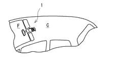
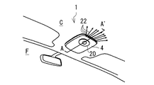
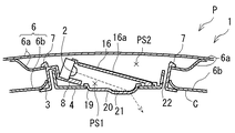
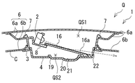
本実施例に係る室内照明装置1は、図1及び図2に示すように、自動車の車室内の天井面CのフロントガラスF寄り側に装着される。この室内照明装置1は、図3及び図4に示すように、1つの発光ダイオード2(本発明に係る「光源」として例示する。)、本体3及びカバー部材4(本発明に係る「昇降部材」として例示する。)を備えている。
[Example 1]
(1) Configuration of Indoor Lighting Device As shown in FIGS. 1 and 2, the
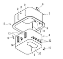
上記本体3は、上下方向を開放した角筒状に形成されている。この本体3は、カバー部材4と共同して発光ダイオード2を囲むようになっている。また、この本体3の上部には、天井部6を構成する車両ボディ6a及び天井材6bのうちの天井材6bの端部に係止する係止部7が設けられている。また、本体3の内部には、斜め下方に向かって延びる舌状の取付部8が設けられている。この取付部8には、その光線が車両の後方斜め下方に向かうように発光ダイオード2が取り付けられている。この発光ダイオード2は、天井面Cより上側に位置して配置されている。
The
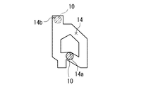
上記カバー部材4は、上方を開放した角箱状に形成されている。このカバー部材4と本体3との間には昇降機構5が設けられており、この昇降機構5により、本体3に対してカバー部材4が昇降可能に設けられている。この昇降機構5は、図6に示すように、本体3の左右側壁の内面に設けられた上下方向に延びる複数の突条9と、カバー部材4の左右側壁の外面に設けられ突条9を案内する複数の案内レール13とを有している。また、この昇降機構5は、本体3の左右側壁の内面に設けられクランク片10の上端部を軸支する軸支部11と、カバー部材4の左右側壁の外面に設けられクランク片10の下端部が挿入される周知のハート状のカム溝14とを有している。そして、図7に示すように、カバー部材4の昇降操作によって、カバー部材4の自重によりクランク片10の下端部をカム溝14の下側係止部14aに係止させる(図7中に実線で示す。)と、本体3に対してカバー部材4が上昇端に位置した状態(図3参照)に位置決めされる。一方、カバー部材4の自重によりクランク片10の下端部をカム溝14の上側係止部14bに係止させる(図7中に仮想線で示す。)と、本体3に対してカバー部材4が下降端に位置した状態(図4参照)に位置決めされるようになっている。
The
上記カバー部材4の底壁には、図3及び図4に示すように、本体3内で斜め上方に延びる反射板16(本発明に係る「反射部」として例示する。)が取り付けられている。この反射板16の上面には、斜め下方に向かう発光ダイオード2からの光線を側方に反射する反射層16a(例えば、メッキ層)が設けられている。この反射層16aは、発光ダイオード2の指向方向に対して僅かに傾斜した反射面を有している。
As shown in FIGS. 3 and 4, a reflecting plate 16 (illustrated as a “reflecting portion” according to the present invention) extending obliquely upward in the
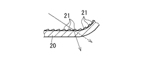
上記カバー部材4の底壁には、カバー部材4が上昇端に位置した状態(図3参照)で発光ダイオード2の指向方向に交差する部位に、長楕円孔状の下方透光部19が形成されている。また、カバー部材4の底壁には、この下方透光部19を覆うように半透明樹脂製のレンズ20が取り付けられている。このレンズ20の内表面には、レンズカット部21が形成されている。このレンズカット部21は、斜め後方に向かう発光ダイオード2の光線を車両の前方寄りに屈折させるような照明パターンとされている(図5参照)。さらに、カバー部材4の後方の側壁には、カバー部材4が下降端に位置した状態(図4参照)で反射板16で反射された発光ダイオード2の指向方向に交差する部位に、円孔状の複数の側方透光部22が形成されている(図6参照)。
On the bottom wall of the
ここで、本実施例の室内照明装置1では、カバー部材4の昇降操作によって、反射板16により下方透光部19が開放され且つ側方透光部22が塞がれる第1照明状態P(図3参照)と、反射板16により下方透光部19が塞がれ且つ側方開口部22が開放される第2照明状態Q(図4参照)と、を切り替えることができるようになっている。すなわち、第1照明状態Pでは、反射板16により、本体3内で、発光ダイオード2及び下方透光部19が連絡される空間PS1と、側方透光部22が存在する空間PS2とが仕切られる。一方、第2照明状態Qでは、本体3内で、発光ダイオード2及び側方透光部22が連絡される空間QS1と下方透光部19が存在する空間QS2とが仕切られるようになっている。
なお、カバー部材4が上昇した状態(図3参照)では、側方透光部22は、本体3の側壁により塞がれるになっている。
Here, in the
In the state where the
(2)室内照明装置の作用
次に、上記構成の室内照明装置1の作用について説明する。
カバー部材4を昇降操作して第1照明状態Pとすると、図3に示すように、反射板16により、下方透光部19が開放され且つ側方透光部22が塞がれる。すると、発光ダイオード2からの光線は、塞がれた状態の側方透光部22を介して側方に漏れず、直接的に開放状態の下方透光部19を透過してレンズ20のレンズカット部21により車両の前方に屈折されて斜め下方に向かい、室内の直接照明が行われる。
(2) Operation of the interior illumination device Next, the operation of the
When the
一方、カバー部材4を昇降操作して第2照明状態Qとすると、図4に示すように、下方透光部19が塞がれ且つ側方開口部22が開放される。すると、発光ダイオード2からの光線は、塞がれた状態の下方透光部19を介して下方に漏れず、反射板16の反射層16aで反射されて開放状態の側方透光部22を透過して側方に向かい、その光線が天井面Cで反射されて間接照明が行われる。この間接照明では、複数の側方透光部22からの光線により天井面Cには王冠状の照明模様が演出される。
On the other hand, when the
(3)実施例の効果
以上より、本実施例の室内照明装置1によると、反射板16を、発光ダイオード2からの光線を側方に向けて反射するように構成し、側方透光部22をカバー部材4に設け、カバー部材4の昇降操作によって、反射板16により下方透光部19が開放され且つ側方透光部22が塞がれる第1照明状態Pと、反射板16により下方透光部19が塞がれ且つ側方開口部22が開放される第2照明状態Qとに切り替え可能としたので、第1照明状態Pでは、発光ダイオード2からの光線は、塞がれた状態の側方透光部22を介して側方に漏れず、直接的に開放状態の下方透光部19を透過して下方に向かい、室内の直接照明が行われる。一方、第2照明状態Qでは、発光ダイオード2からの光線は、塞がれた状態の下方透光部19を介して下方に漏れず、反射板16で反射されて開放状態の側方透光部22を透過して側方に向かい、その光線が天井面Cで反射されて間接照明が行われる。このように、室内の直接照明である第1照明状態Pと天井面の間接照明である第2照明状態Qとを切り替えることができるので、室内の照明による演出効果を高めることができる。さらに、カバー部材4の昇降距離を必要最小限として、照明装置1の小型化を図ることができる。
(3) Effects of the Embodiment As described above, according to the
また、本実施例では、発光ダイオード2を天井面Cより上側に位置するように配置したので、照明装置1の天井面Cから下方側への突出量を小さくでき、見栄えを高めることができる。
Further, in the present embodiment, the
また、本実施例では、下方透光部19に、発光ダイオード2からの光線の向きを変えるレンズカット部21を設けたので、第1照明状態において、適当な方向性を持つ室内の直接照明とすることができる。
In the present embodiment, since the lower
また、本実施例では、側方透光部22を複数設けたので、第2照明状態において、任意の模様付きの間接照明を演出することができる。
In the present embodiment, since the plurality of side
また、本実施例では、光源として指向性を有する発光ダイオード2を用いたので、反射板16での反射方向を正確に制御できる。そのため、より適当な直接照明及び間接照明を行うことができる。
In this embodiment, since the
また、本実施例では、発光ダイオード2を1つとしたので、照明装置1の小型化が可能となる。
In this embodiment, since the number of the
また、本実施例では、本体3に発光ダイオード2を取り付けるようにしたので、発光ダイオード2が一体化された本体4を天井部6に取り付けることができ、天井部6に対する照明装置1の取付性を高めることができる。
In the present embodiment, since the
さらに、本実施例では、室内照明装置1を車両用としたので、車両の車室内天井を効果的に照明することができる。
Furthermore, in the present embodiment, since the
〔実施例2〕
次に、実施例2に係る室内照明装置について説明する。なお、本実施例2において、上記実施例1の室内照明装置と同じ構成部位には同符号を付けて詳説を省略し、以下に相違点について詳説する。
[Example 2]
Next, an interior lighting device according to Example 2 will be described. In the second embodiment, the same components as those in the indoor lighting device of the first embodiment are denoted by the same reference numerals and detailed description thereof is omitted, and the differences will be described in detail below.
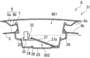
本実施例に係る室内照明層31は、図8及び図9に示すように、1つの発光ダイオード32(本発明に係る「光源」として例示する。)、本体33及びカバー部材34(本発明に係る「昇降部材」として例示する。)を備えている。
As shown in FIGS. 8 and 9, the
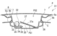
上記本体33は、上下方向を開放した角筒状に形成されている。この本体33は、カバー部材34と共同して発光ダイオード32を囲むようになっている。また、この本体33の上部には、天井部6を構成する車両ボディ6a及び天井材6bのうちの天井材6bの端部に係止する係止部7が設けられている。また、本体33の内部には、水平に向かって延びる舌状の取付部35が設けられている。この取付部35には、その光線が車両の側方に向かうように発光ダイオード32が取り付けられている。また、本体33の車両後方の側壁には、カバー部材34が下降端に位置した状態(図9参照)で発光ダイオード32の指向方向と交差する部位に複数の側方透光部36が形成されている。
The
上記カバー部材34は、上方を開放した角箱状に形成されている。このカバー部材34は、上記実施例1と同様の昇降機構5によって本体33内に昇降可能に設けられている。このカバー部材34の底壁には、本体33内で斜め上方に延びる反射板37(本発明に係る「反射部」として例示する。)が設けられている。この反射板37の下面には、側方に向かう発光ダイオード2からの光線を斜め下方に反射する反射層37a(例えば、メッキ層)が設けられている。この反射層37aは、発光ダイオード32の指向方向に対して傾斜した反射面を有している。
The
上記カバー部材34の底壁には、カバー部材34が上昇端に位置した状態(図8参照)で反射板37で反射された発光ダイオード32の指向方向に交差する部位に、長楕円孔状の下方透光部38が形成されている。
On the bottom wall of the
ここで、本実施例の室内照明装置31では、カバー部材34の昇降操作によって、反射板37により下方透光部38が開放され且つ側方透光部36が塞がれる第1照明状態P(図8参照)と、反射板37により下方透光部38が塞がれ且つ側方開口部36が開放される第2照明状態Q(図9参照)と、を切り替えることができるようになっている。すなわち、第1照明状態Pでは、反射板37により、本体33内で、発光ダイオード32及び下方透光部38が連絡される空間PS1と、側方透光部36が存在する空間PS2とが仕切られる。一方、第2照明状態Qでは、本体33内で、発光ダイオード32及び側方透光部36が連絡される空間QS1と、下方透光部38が存在する空間QS2とが仕切られるようになっている。
Here, in the
(2)室内照明装置の作用
次に、上記構成の室内照明装置31の作用について説明する。
カバー部材34を昇降操作して第1照明状態Pとすると、図8に示すように、反射板37により、下方透光部38が開放され且つ側方透光部36が塞がれる。すると、発光ダイオード32からの光線は、塞がれた状態の側方透光部36を介して側方に漏れず、反射板37で反射されて開放状態の下方透光部38を透過して車両後方の斜め下方に向かい、室内の直接照明が行われる。
(2) Operation of the interior illumination device Next, the operation of the
When the
一方、カバー部材34を昇降操作して第2照明状態Qとすると、図9に示すように、下方透光部38が塞がれ且つ側方開口部36が開放される。すると、発光ダイオード32からの光線は、塞がれた状態の下方透光部38を介して下方に漏れず、直接的に開放状態の側方透光部36を透過して側方に向かい、その光線が天井面Cで反射されて間接照明が行われる。この間接照明では、複数の側方透光部36からの光線により天井面Cには王冠状の照明模様が演出される。
On the other hand, when the
(3)実施例の効果
以上より、本実施例の室内照明装置31によると、上記実施例1の室内照明装置1と略同じ作用・効果を奏すると共に、反射部37を、発光ダイオード32からの光線を下方に向けて反射するように構成し、側方透光部36を本体33に設け、カバー部材34の昇降操作によって、反射板37により下方透光部38が開放され且つ側方透光部36が塞がれる第1照明状態Pと、反射板37により下方透光部38が塞がれ且つ側方開口部36が開放される第2照明状態Qとに切り替え可能としたので、第1照明状態Pでは、発光ダイオード32からの光線は、塞がれた状態の側方透光部36を介して側方に漏れず、反射板37で反射されて開放状態の下方透光部38を透過して下方に向かい、室内の直接照明が行われる。一方、第2照明状態Qでは、発光ダイオード32からの光線は、塞がれた状態の下方透光部38を介して下方に漏れず、直接的に開放状態の側方透光部36を透過して側方に向かい、その光線が天井面Cで反射されて間接照明が行われる。このように、室内の直接照明である第1照明状態Pと天井面Cの間接照明である第2照明状態Qとを切り替えることができるので、室内の照明による演出効果を高めることができる。さらに、カバー部材34の昇降距離を必要最小限として、照明装置1の小型化を図ることができる。
(3) Effect of Example As described above, according to the
尚、本発明においては、上記実施例1及び2に限られず、目的、用途に応じて本発明の範囲内で種々変更した実施例とすることができる。即ち、上記実施例1及び2では、第1及び第2照明状態P,Qの異なる2種類の照明状態を切り替えるようにしたが、これに限定されず、例えば、異なる3種類以上の照明状態を切り替えるようにしてもよい。 In the present invention, the present invention is not limited to the first and second embodiments, and various modifications can be made within the scope of the present invention depending on the purpose and application. That is, in the first and second embodiments, two types of illumination states having different first and second illumination states P and Q are switched. However, the present invention is not limited to this, and for example, three or more different illumination states are selected. You may make it switch.
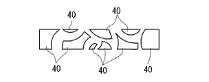
また、上記実施例1及び2では、円孔状の側方透光部22,36を例示したが、これに限定されず、例えば、図10に示すように、所定の図柄形状(例えば、異形状、星形状、ハート形状等)に形成された側方透光部40としてもよい。
Further, in the first and second embodiments, the circular hole-shaped side light-transmitting
また、上記実施例1及び2では、複数の側方透光部22,36の全てを同じ形状とした形態を例示したが、これに限定されず、例えば、図10に示すように、複数の側方透光部40の全てを異なる形状としてもよい。また、複数の側方透光部を複数組に分けてそれらの複数組で異なる形状としてもよい。
Moreover, in the said Example 1 and 2, although the form which made all the some side
また、上記実施例1及び2では、カバー部材4,34に下方透光部19,38を覆うレンズ20を設けるようにしたが、これに限定されず、例えば、カバー部材4,34に下方透光部19,38を覆う半透明フィルムを設けるようにしてもよい。これにより、半透明フィルムにより本体の内部構造を隠すことができ、見栄えを高めることができる。この半透明フィルムは、例えば、ハーフミラーからなっていることができる。
In the first and second embodiments, the
また、上記実施例1及び2では、室内照明装置1,31として平面矩形の形態を例示したが、これに限定されず、例えば、平面円形、楕円、異形等の室内照明装置としてもよい。
Moreover, in the said Example 1 and 2, although the planar rectangular form was illustrated as the
さらに、上記実施例1及び2では、車両の天井面CのフロントガラスF寄り側に配置される室内照明装置1,31を例示したが、これに限定されず、例えば、車両の天井面Cの略中央部に配置される室内照明装置としてもよい。
Furthermore, in the said Example 1 and 2, although the
演出効果を高めて室内を照明する技術として広く利用される。特に、車両の車室内を照明する技術として好適に利用される。 Widely used as a technology to enhance the production effect and illuminate the room. In particular, it is suitably used as a technique for illuminating the interior of a vehicle.
1,31;室内照明装置、2,32;発光ダイオード、3,33;本体、4,34;カバー部材、6;天井部、16,37;反射板、19,38;下方透光部、21;レンズカット部、22,36;側方透光部、C;天井面、P;第1照明状態、Q;第2照明状態。
DESCRIPTION OF
Claims (9)
天井部に取り付けられ、前記光源を囲む本体と、
前記本体に対して昇降可能に設けられ、前記光源からの光線を反射する反射部を有する昇降部材と、を備え、
前記昇降部材には下方透光部が設けられており、前記昇降部材又は前記本体には側方透光部が設けられており、
前記昇降部材の昇降操作によって、該反射部により前記下方透光部が開放され且つ前記側方透光部が塞がれる第1照明状態と、該反射部により前記下方透光部が塞がれ且つ前記側方開口部が開放される第2照明状態と、を切り替えることができることを特徴とする室内照明装置。 A light source;
A body attached to the ceiling and surrounding the light source;
An elevating member that is provided so as to be movable up and down with respect to the main body and has a reflecting portion that reflects a light beam from the light source;
The elevating member is provided with a lower translucent part, and the elevating member or the main body is provided with a side translucent part,
By the raising / lowering operation of the elevating member, the lower light transmitting portion is opened by the reflecting portion and the side light transmitting portion is blocked, and the lower light transmitting portion is blocked by the reflecting portion. And the interior lighting apparatus characterized by being able to switch between the 2nd lighting states by which the said side opening part is open | released.
前記側方透光部は、前記昇降部材に設けられており、
前記第1照明状態では、前記光源からの光線が前記下方透光部を透過し、
前記第2照明状態では、前記反射部により側方に向けて反射された前記光源からの光線が前記側方透光部を透過する請求項1記載の室内照明装置。 The reflection unit is configured to reflect the light beam from the light source toward the side,
The lateral translucent part is provided on the lifting member,
In the first illumination state, a light beam from the light source passes through the lower light transmitting part,
The indoor lighting device according to claim 1, wherein in the second illumination state, a light beam from the light source reflected toward the side by the reflecting portion passes through the side light transmitting portion.
前記側方透光部は、前記本体に設けられており、
前記第1照明状態では、前記反射部により下方に向けて反射された前記光源からの光線が前記下方透光部を透過し、
前記第2照明状態では、前記光源からの光線が前記側方透光部を透過する請求項1記載の室内照明装置。 The reflection portion is configured to reflect the light beam from the light source downward.
The lateral translucent part is provided in the main body,
In the first illumination state, a light beam from the light source reflected downward by the reflecting portion passes through the lower light transmitting portion,
The indoor lighting device according to claim 1, wherein in the second illumination state, a light beam from the light source passes through the side light transmitting portion.
Priority Applications (1)
| Application Number | Priority Date | Filing Date | Title |
|---|---|---|---|
| JP2008321459A JP2010143345A (en) | 2008-12-17 | 2008-12-17 | Indoor lighting device |
Applications Claiming Priority (1)
| Application Number | Priority Date | Filing Date | Title |
|---|---|---|---|
| JP2008321459A JP2010143345A (en) | 2008-12-17 | 2008-12-17 | Indoor lighting device |
Publications (1)
| Publication Number | Publication Date |
|---|---|
| JP2010143345A true JP2010143345A (en) | 2010-07-01 |
Family
ID=42564229
Family Applications (1)
| Application Number | Title | Priority Date | Filing Date |
|---|---|---|---|
| JP2008321459A Pending JP2010143345A (en) | 2008-12-17 | 2008-12-17 | Indoor lighting device |
Country Status (1)
| Country | Link |
|---|---|
| JP (1) | JP2010143345A (en) |
-
2008
- 2008-12-17 JP JP2008321459A patent/JP2010143345A/en active Pending
Similar Documents
| Publication | Publication Date | Title |
|---|---|---|
| EP2524841B1 (en) | Vehicle lighting unit | |
| JP4937649B2 (en) | Vehicle lighting | |
| JP5210061B2 (en) | Lamp | |
| JP2006236588A (en) | Light illumination device and vehicular lamp | |
| CN104937329B (en) | Vehicle lamp structure | |
| WO2014112288A1 (en) | Vehicle lamp structure | |
| US9695990B2 (en) | Arrangement for light emission | |
| JP6975587B2 (en) | Vehicle lighting | |
| JP2015076249A (en) | Vehicular lighting fixture | |
| JP2010021002A (en) | Lighting fixture | |
| JP2020087624A (en) | Vehicular lighting fixture | |
| JP2017033661A (en) | Vehicular lighting fixture | |
| JP2011148406A (en) | Luminaire for vehicle | |
| JP6383583B2 (en) | Vehicle lighting device | |
| JP2010143346A (en) | Indoor lighting device | |
| JP6221438B2 (en) | Vehicle lighting | |
| JP2010143345A (en) | Indoor lighting device | |
| JP5457780B2 (en) | Vehicle lamp | |
| KR101176509B1 (en) | Automotive LED lights indirect lighting | |
| JP2016043727A (en) | Illumination device for vehicle cabin | |
| JP2013201101A (en) | Luminaire | |
| JP2008171747A (en) | lamp | |
| JP2011018563A (en) | Lighting tool for vehicle | |
| JP2011086466A (en) | Lamp unit | |
| JP2010102888A (en) | Lighting system for window |