JP2010143555A - Vehicular door - Google Patents
Vehicular door Download PDFInfo
- Publication number
- JP2010143555A JP2010143555A JP2008326621A JP2008326621A JP2010143555A JP 2010143555 A JP2010143555 A JP 2010143555A JP 2008326621 A JP2008326621 A JP 2008326621A JP 2008326621 A JP2008326621 A JP 2008326621A JP 2010143555 A JP2010143555 A JP 2010143555A
- Authority
- JP
- Japan
- Prior art keywords
- door
- vehicle
- upward
- panel
- moving
- Prior art date
- Legal status (The legal status is an assumption and is not a legal conclusion. Google has not performed a legal analysis and makes no representation as to the accuracy of the status listed.)
- Withdrawn
Links
Images


Landscapes
- Air Bags (AREA)
- Vehicle Interior And Exterior Ornaments, Soundproofing, And Insulation (AREA)
Abstract
Description
本発明は、車両用ドアに関するものであり、側方からの衝突などの荷重入力時に乗員を保護することができる車両用ドアに関するものである。 The present invention relates to a vehicle door, and more particularly to a vehicle door that can protect an occupant when a load such as a collision from the side is input.
図5は従来のドア及び乗員を示した一例の概略図である。車両のドア104の車両内側にはシート132が配置され、シート132に乗員102が座るように構成されている。
ドア104は、車両の外板をなすアウタパネル110と、アウタパネル110の車両内側に配されてアウタパネル110とともにウインドガラス(不図示)、ドアロックシステム(不図示)等の収容空間を形成するインナパネル108と、インナパネル108の車両内側に取り付けられたドアトリム106とから構成されている。
FIG. 5 is a schematic diagram showing an example of a conventional door and an occupant. A
The door 104 includes an
アウタパネル110とインナパネル108の間、及びインナパネル108とドアトリム106の間であり、乗員102の腰部Wと略同じ高さ位置には車両前後方向に延びるエネルギー吸収部材(以下EA部材と称する)136が配されている。また、車両側方から衝突するなど、車両への側方からの荷重入力時には、乗員102とドア104との間にサイドエアバック(SAB)138が作動して乗員を保護するように構成されている。
また、図5に示した車両は、視認性を向上させるためにドア104の上部に位置するドアガラス(不図示)を広くとると同時にベルトライン134の高さ位置が下がり、乗員102が一般成人である場合には肩部Xがベルトライン134よりも上方に位置するようなドア104構造となっている。
An energy absorbing member (hereinafter referred to as an EA member) 136 extending between the
Further, in the vehicle shown in FIG. 5, the door glass (not shown) located above the door 104 is widened to improve the visibility, and at the same time the height of the
このようなドア104を有する車両が側面衝突した場合に乗員が受ける衝撃について図6を用いて説明する。図6は従来のドア104を有する車両が側面から衝突した場合に乗員が受ける衝撃の説明図であり、図6(A)は衝突前を表す図であり、図6(B)は衝突時を表す図である。
図6(A)に示したような衝突前の状態から、ドア104に衝突物130が側面から衝突すると、乗員102を保護するためにサイドエアバック138が作動する。そして、図6(B)に示したように衝撃により乗員102は車両外側に傾き、ドア104の上部に位置する胸部Yと、ドア104の下部に位置する腰部Wに大きな荷重が入力される。腰部は人体耐性が高いことに加え、EA部材136により荷重の一部が吸収されるため保護が可能であるが、胸部は人体耐性が低いため、サイドエアバック138のみならず更なる保護が必要である。
The impact received by the occupant when a vehicle having such a door 104 undergoes a side collision will be described with reference to FIG. FIG. 6 is an explanatory view of the impact received by the occupant when a vehicle having a conventional door 104 collides from the side, FIG. 6 (A) is a diagram showing the state before the collision, and FIG. FIG.
When the
人体耐性は、肩部X及び腰部Wが高く、胸部Yが低い。そのため、車両が側面から衝突した時に乗員102を保護するためには、人体耐性の高い肩部X及び腰部Wへ衝突によるエネルギーを伝達し、衝突によって車両内側へ侵入してくるドア104から乗員102をいち早く遠ざけ、且つ人体耐性の低い胸部Yへの入力を低減するため胸部Yとドア104との間にスペースを確保することが必要である。しかし、図5に示したような肩部がベルトライン134よりも上方に位置するようなドアの構造では、肩部Xとドア104との接触位置にEA材の設置が不可能であり、そのため肩部Xへの荷重の入力と、胸部Yとドア104との間のスペースの確保が困難であり、人体耐性の低い胸部Yへの入力を低減することができない。
The human body tolerance is high in the shoulder X and the waist W and low in the chest Y. Therefore, in order to protect the
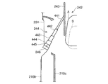
そのため、乗員の肩部がベルトラインよりも上方となるドア構造であっても肩部に荷重を入力する技術が特許文献1に開示されている。図7は特許文献1に係る実施形態を示す図である。
図7に示したように、ドアトリム216cの上方部分に、可動パネル(衝撃吸収パネル)243と、5つの円筒状パネル441〜445から形成される伸縮機構(移動部材)244とから構成された隔離手段242が配置されており、通常時は隔離手段242はドアトリムの一部を成し、車両の側面衝突時は伸縮機構244が駆動することで図7に示したように可動パネル243が上方且つ車両内側方向へ移動し乗員の肩部に荷重が入力されるように構成されている。
For this reason, Patent Document 1 discloses a technique for inputting a load to a shoulder portion even in a door structure in which the shoulder portion of the occupant is above the belt line. FIG. 7 is a diagram showing an embodiment according to Patent Document 1. In FIG.
As shown in FIG. 7, in the upper part of the
しかしながら、特許文献1に開示された技術においては、衝撃吸収パネルである可動パネル243が車両内側方向即ち乗員方向に移動するため、可動パネル243が乗員に近づくことによる乗員へ大きな荷重がかかり、肩部への負担が過度に大きくなる。特に車両への衝突の衝撃が大きいとその負担が大きい。
また、隔離手段242の稼動時には伸縮機構244が外部に露出されるため、衝突の衝撃により乗員身体の一部が伸縮機構244を構成する円筒状パネル441〜445間に挟まれるなど、乗員へ危害を加える恐れがある。
従って、胸部への負担低減を含めた安全性向上の観点では十分とはいえない。
However, in the technique disclosed in Patent Document 1, since the
Further, since the expansion /
Therefore, it cannot be said that it is sufficient in terms of safety improvement including reduction of the burden on the chest.
従って、本発明はかかる従来技術の問題に鑑み、ベルトラインが乗員の肩部よりも低い車両においても、車両の側面への衝突時に、人体耐性の高い肩部及び腰部へ衝突によるエネルギーを伝達し、衝突によって車両内側へ侵入してくるドアから乗員をいち早く遠ざけ、且つ人体耐性の低い胸部へのエネルギーの入力を低減するため胸部とドアとの間にスペースを確保することができる車両用ドアを提供することを目的とする。 Therefore, in view of such a problem of the prior art, the present invention transmits energy due to the collision to the shoulder and waist which are highly resistant to the human body, even in a vehicle where the belt line is lower than the shoulder of the occupant. A vehicle door which can secure a space between the chest and the door in order to keep the occupant away from the door entering the vehicle due to the collision and reduce the input of energy to the chest with low human resistance. The purpose is to provide.
上記課題を解決するため本発明においては、車両のドアパネルと、該ドアパネルの室内側に取り付けられるドアトリムからなる車両用ドアにおいて、前記ドアトリムは、前記ドアパネルに固定されるドアトリム本体と、該ドアトリム本体と分割されて上方に移動可能な上方移動部とから構成され、前記上方移動部とドアパネルとの間に、前記上方移動部とともに上方に移動可能な衝撃吸収材を収容し、前記車両への側方からの荷重入力時に、前記上方移動部を前記衝撃吸収材とともに上方に移動させる移動手段を設けたことを特徴とする。 In order to solve the above problems, in the present invention, in a vehicle door comprising a vehicle door panel and a door trim attached to the interior side of the door panel, the door trim includes a door trim main body fixed to the door panel, the door trim main body, An upward moving part that is divided and movable upward is housed between the upward moving part and the door panel, and accommodates an impact absorbing material that is movable upward together with the upward moving part, and is lateral to the vehicle. A moving means is provided for moving the upward moving part upward together with the shock absorbing material when a load is input from the vehicle.
車両への側方からの荷重入力時に、前記上方移動部を前記衝撃吸収材とともに上方へ移動させることで、上方移動部及び衝撃吸収材を乗員の肩部の高さ位置まで移動することができ、ベルトラインが乗員の肩部よりも低い車両においても、車両への側方からの荷重入力によるエネルギーを適切に肩部へ伝達することができる。
また、車両への側方からの荷重入力時に前記上方移動部が衝撃吸収材とともに上方へ移動するため、通常時、即ち側方からの荷重非入力時に前記上方移動部及び衝撃吸収材が位置していた場所にスペースができる。該スペースの存在により、車両の側方からの荷重入力時に乗員の胸部とドアとの間のスペースを確保することができ、乗員の胸部への車両側方からの荷重入力によるエネルギーの伝達を低減することができる。
これにより、ベルトラインの高さ位置が乗員の肩部の高さ位置よりも低い車両においても、側方からの荷重の入力に対して乗員を保護することができるため、車両のレイアウトの自由度が高まる。
When the load is input from the side to the vehicle, the upper moving portion and the shock absorbing material can be moved to the height position of the occupant's shoulder by moving the upper moving portion together with the shock absorbing material. Even in a vehicle in which the belt line is lower than the shoulder portion of the occupant, energy due to load input from the side to the vehicle can be appropriately transmitted to the shoulder portion.
In addition, since the upward moving portion moves upward together with the shock absorber when a load is input from the side to the vehicle, the upward moving portion and the shock absorber are located in a normal state, that is, when no load is input from the side. There is a space where it was. Due to the existence of this space, a space between the passenger's chest and the door can be secured when a load is input from the side of the vehicle, and energy transmission due to the load input from the side of the vehicle to the passenger's chest is reduced. can do.
As a result, even in a vehicle in which the height position of the belt line is lower than the height position of the shoulder portion of the occupant, the occupant can be protected against the input of a load from the side. Will increase.
また、前記移動手段は、前記ドアトリム本体と前記ドアパネルとの間に配置したことを特徴とする。
このようにして前記移動手段を配置することで、移動手段は車両内側ではドアトリム本体に覆われる。移動手段が外部に露出されずにドアトリム本体に覆われていることによって、乗員に直接移動手段が衝突することを回避することができる。
Further, the moving means is arranged between the door trim main body and the door panel.
By disposing the moving means in this way, the moving means is covered with the door trim body inside the vehicle. Since the moving means is covered with the door trim main body without being exposed to the outside, it is possible to prevent the moving means from directly colliding with the occupant.
また、前記上方移動部は、前記ドアトリム本体と車幅方向にオーバーラップして、前記上方移動部と前記ドアトリムとの間に、前記衝撃吸収材を収容していることを特徴とする。
これにより、荷重非入力時の前記衝撃吸収材の収容部は、前記上方移動部及び衝撃吸収材が上方へ移動したときに、車両外側へへこむ凹部(スペース)を形成することとなり、車両側方からの荷重入力時に、乗員と車両(ドアトリム)との距離を長く確保することができる。
In addition, the upward movement part overlaps the door trim main body in the vehicle width direction, and houses the shock absorbing material between the upward movement part and the door trim.
As a result, when the load is not input, the shock absorber housing portion forms a recess (space) that is recessed toward the outside of the vehicle when the upward moving portion and the shock absorber move upward. When a load is input from the vehicle, a long distance between the passenger and the vehicle (door trim) can be secured.
また、前記ドアパネルは、室外側から順にアウタパネルとインナパネルが配されており、前記移動手段は、下部を前記インナパネルに固定され、上部を前記上方移動部に固定された圧縮バネと、前記上方移動部に取り付けられた車両外側を向いた突起部と、前記インナパネルに設けられ前記突起部を嵌合可能な嵌合孔と、前記突起部先端と対向する位置で前記アウタパネルの車両内側に取り付けられたプッシュロッドとから構成され、前記圧縮バネが弾性変形した状態で前記突起部を前記嵌合孔に嵌合させることで、前記上方移動部を前記インナパネルに固定し、前記車両への側方からの荷重入力時に、該荷重により前記プッシュロッドが車両内側方向へ移動することで前記突起部を前記嵌合孔から外し、前記圧縮バネの復元力により前記上方移動部を上方へ移動させることを特徴とする。 The door panel includes an outer panel and an inner panel in order from the outdoor side, and the moving means includes a compression spring having a lower part fixed to the inner panel and an upper part fixed to the upper moving part, and the upper part Mounted on the inner side of the outer panel at a position facing the front end of the protrusion, a protrusion provided on the moving part facing the outside of the vehicle, a fitting hole provided in the inner panel and capable of fitting the protrusion. The upper moving portion is fixed to the inner panel by fitting the protrusion into the fitting hole in a state where the compression spring is elastically deformed, and the side toward the vehicle is configured. When the load is input from the direction, the push rod is moved inward of the vehicle by the load, so that the protrusion is removed from the fitting hole, and the upper force is restored by the restoring force of the compression spring. And wherein the moving the moving portion upward.
車両の側方からの荷重入力時には、前記アウタパネルが衝撃により車両内側方向に押され、前記プッシュロッドが内側に移動する。プッシュロッドの移動により前記突起部を嵌合穴から押し出すことで、前記上方移動部とインナパネルとの固定が解除されるため、前記圧縮バネの復元力により上方移動部を上方へ移動させることができる。
これにより、簡単な機構で側方からの荷重の入力に対して乗員を保護することができる。
When a load is input from the side of the vehicle, the outer panel is pushed inward by the impact and the push rod moves inward. By pushing out the protrusion from the fitting hole by moving the push rod, the upper moving part and the inner panel are released from being fixed. Therefore, the upper moving part can be moved upward by the restoring force of the compression spring. it can.
Thereby, a passenger | crew can be protected with respect to the input of the load from a side with a simple mechanism.
また、前記移動手段は、前記車両への側方からの荷重入力を検知する検知手段と、火薬の爆発によってシリンダ内のピストンを作動させる火薬シリンダから構成され、前記火薬シリンダのシリンダを前記ドアパネルに固定するとともに、前記ピストンを前記上方移動部に固定し、前記検知手段により車両への側方からの荷重入力を検知すると、前記火薬シリンダを作動させ、前記上方移動部を上方へ移動させることを特徴とする。 The moving means includes detection means for detecting a load input from the side to the vehicle, and a gunpowder cylinder that operates a piston in the cylinder by an explosion of gunpowder, and the cylinder of the gunpowder cylinder is attached to the door panel. And fixing the piston to the upward movement part, and detecting the load input from the side to the vehicle by the detection means, actuating the explosive cylinder and moving the upward movement part upward. Features.
前記検知手段としては、車両のBピラー内部に備えられた側面衝突を検知するセンサや、サイドエアバックを作動させるためのエアバックECUなど、従来より備えられているものを兼用することができる。
これにより、例えばアウタパネルが真っ直ぐ車両内側方向に移動せず、車両内側後方などに移動した場合などにおいても、車両への側方からの荷重入力を検知すると前記上方移動部を上方へ移動させることが可能であり、衝突の状態に左右されず乗員の保護が可能となる。
As the detection means, those conventionally provided such as a sensor for detecting a side collision provided in the B pillar of the vehicle and an airbag ECU for operating the side airbag can be used.
As a result, for example, even when the outer panel does not move straight inward of the vehicle but moves backward inward of the vehicle, the upward moving portion can be moved upward when a load input from the side to the vehicle is detected. It is possible to protect the passengers regardless of the state of the collision.
また、前記移動手段は、前記車両への側方からの荷重入力を検知する検知手段と、下部を前記ドアパネルに固定され上部を前記上方移動部に固定された圧縮バネと、前記上方移動部に設けられ車両外側を向いた突起部と、前記ドアパネルに設けられ、前記突起部を嵌合可能な嵌合孔と、前記突起部を嵌合穴から取り外し可能な取り外し手段とから構成され、前記圧縮バネが弾性変形した状態で前記突起部を前記嵌合孔に嵌合させることで、前記上方移動部を前記インナパネルに固定し、前記検知手段により車両への側方からの荷重入力を検知すると、前記取り外し手段によって前記突起部を前記嵌合孔から外し、前記圧縮バネの復元力により前記上方移動部を上方へ移動させることを特徴とする。 The moving means includes a detecting means for detecting a load input from the side to the vehicle, a compression spring having a lower part fixed to the door panel and an upper part fixed to the upper moving part, and an upper moving part. A protrusion provided on the door panel, a fitting hole provided in the door panel, into which the protrusion can be fitted, and a detaching means capable of removing the protrusion from the fitting hole; When the protrusion is fitted into the fitting hole in a state where the spring is elastically deformed, the upper moving portion is fixed to the inner panel, and when the load input from the side to the vehicle is detected by the detecting means. The protruding portion is removed from the fitting hole by the removing means, and the upward moving portion is moved upward by the restoring force of the compression spring.
これにより、衝突の状態に左右されず乗員の保護が可能であるとともに、簡単な機構で乗員の保護が可能となる。 Accordingly, the occupant can be protected regardless of the state of the collision, and the occupant can be protected with a simple mechanism.
以上記載のごとく本発明によれば、ベルトラインが乗員の肩部よりも低い車両においても、車両の側面への衝突時に、人体耐性の高い肩部及び腰部へ衝突によるエネルギーを伝達し、衝突によって車両内側へ侵入してくるドアから乗員をいち早く遠ざけ、且つ人体耐性の低い胸部へのエネルギーの入力を低減するため胸部とドアとの間にスペースを確保することができる車両用ドアを提供することができる。
また、ベルトラインの高さに寄与することなく乗員保護性能を確保できるので、デザインの自由度が増す。
As described above, according to the present invention, even in a vehicle in which the belt line is lower than the shoulder of the occupant, energy caused by the collision is transmitted to the shoulder and waist that have high human body resistance when the vehicle collides with the side of the vehicle. To provide a vehicle door capable of ensuring a space between the chest and the door in order to quickly move an occupant away from the door entering the vehicle and reduce the input of energy to the chest with low human resistance. Can do.
In addition, occupant protection performance can be ensured without contributing to the height of the belt line, thereby increasing the degree of freedom in design.
以下、図面を参照して本発明の好適な実施例を例示的に詳しく説明する。但しこの実施例に記載されている構成部品の寸法、材質、形状、その相対的配置等は特に特定的な記載がない限りは、この発明の範囲をそれに限定する趣旨ではなく、単なる説明例に過ぎない。 Hereinafter, exemplary embodiments of the present invention will be described in detail with reference to the drawings. However, the dimensions, materials, shapes, relative arrangements, and the like of the components described in this embodiment are not intended to limit the scope of the present invention unless otherwise specified, but are merely illustrative examples. Not too much.
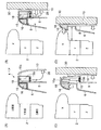
図1は、実施例1における車両のドア及び乗員を示した概略図である。図1(A)は通常時、図1(B)〜図1(D)は側面衝突時を表し、図1(A)の状態から車両が衝突物に側面衝突し、図1(B)、図1(C)、図1(D)の順に時間が経過している。 FIG. 1 is a schematic diagram illustrating a vehicle door and an occupant in the first embodiment. FIG. 1A shows a normal state, and FIGS. 1B to 1D show a side collision, and the vehicle collides with a collision object from the state of FIG. 1A. Time elapses in the order of FIG. 1C and FIG.
図1(A)において、ドア4の車両内側にはシート(不図示)が配置され、該シートに乗員2が座るように構成されている。
ドア4は、車両の外板をなすアウタパネル10と、アウタパネル10の車両内側に配されてアウタパネル10とともにウインドガラス(不図示)、ドアロックシステム(不図示)等の収容空間を形成するインナパネル8と、インナパネル8の車両内側に取り付けられ内装品(不図示)が取り付けられるドアトリムとから構成されている。
また、視認性を向上させるためにドア4の上部に位置するドアガラス(不図示)を広くとると同時にベルトラインの高さ位置が下がり、乗員2が一般成人である場合には肩部Xがベルトラインよりも上方に位置するようなドア4構造となっている。
In FIG. 1A, a seat (not shown) is arranged on the vehicle interior side of the
The
Further, in order to improve the visibility, a wide door glass (not shown) located at the top of the
前記ドアトリムは、ドアトリム(ロア)(以下ドアトリム本体と称する)6と、ドアトリム(アッパ)(以下上方移動部と称する)18とから構成されている。また、上方移動部18の下部には圧縮バネ14の上部が固定されており、該圧縮バネ14の下部はインナパネル8の上部に固定されている。上方移動部18に設けた突起状のストッパ20をインナパネル8に設けた嵌合孔に嵌合させることで前記圧縮バネ14が十分に圧縮された状態で、上方移動部18がドアトリム本体6の上部でドアトリム本体6と一体化するように固定されている。また、圧縮バネ14の軸心には車両上下方向に立設されたロッド状のガイド22が設けられている。
また、ストッパ20の先端部と対向する位置で、アウタパネル10の車両内側にプッシュロッド12が取り付けられている。
The door trim includes a door trim (lower) (hereinafter referred to as a door trim main body) 6 and a door trim (upper) (hereinafter referred to as an upward moving portion) 18. The upper part of the
A
さらに、上方移動部18とドアトリム本体6とは、ドアトリム本体6の上部で車幅方向にオーバーラップしており、上方移動部18とドアトリム本体6との間に出来る空間には車両前後方向に延びるエネルギー吸収材(以下EA部材と称する)16が上方移動部18に固定されて配置されている。
Further, the upper moving
図1(A)に示された構成のドア4の側面に衝突物30が衝突すると、図1(B)に示したように衝突による荷重の車両内側方向への入力によって、ドア4を構成するアウタパネル10が車両内側方向へ侵入する。アウタパネル10の車両内側方向への侵入により、上方移動部18に設けられた突起状のストッパ20と対向する位置に設けられたプッシュロッド12がストッパ20に徐々に近づき、最後にはストッパ20をインナパネル8に設けた嵌合孔から押し出す。
When the colliding
プッシュロッド12によってストッパ20がインナパネル8に設けた嵌合孔から押し出されると、上方移動部18のインナパネル8への固定が解除されるため、図1(C)に示したように、圧縮バネ14の復元力によって上方移動部18及びEA部材16がガイド22に沿って乗員2の肩部Xの高さ位置と略同じ高さ位置まで上方に移動する。
When the
衝突物30による荷重の入力が進むと、ドア4と乗員2が衝突するが、図1(D)に示したように、上方移動部18及びEA部材16が肩部Xと略同じ高さ位置まで移動しているため、衝突によるエネルギーが適切に人体耐性の高い肩部に伝達される。
さらに、図1(A)に示した通常時に上方移動部18及びEA部材16が位置していた場所は、上方移動部18及びEA部材16が上方に移動することによってスペースができるため、人体耐性の低い胸部への衝突によるエネルギーの伝達を低減することができる。このようにして出来るスペースで開くように車両の側面衝突時に作動するサイドエアバックを設けることもできる。
さらにまた、圧縮バネ14、ストッパ20、ガイド22、プッシュロッド12から構成され、通常時は上方移動手段を定位置に固定し、側方からの荷重入力時には上方移動部18を上方へ移動させる移動手段は、ドアトリム本体に覆われているため、前記移動手段と乗員とが直接衝突することを回避することができる。
When the input of the load by the colliding
Furthermore, the place where the upward moving
Furthermore, it is composed of a
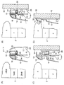
図2は、実施例2における車両のドア及び乗員を示した概略図である。図2(A)は通常時、図2(B)〜図2(D)は側面衝突時を表し、図2(A)の状態から車両が衝突物に側面衝突し、図2(B)、図2(C)、図2(D)の順に時間が経過している。 FIG. 2 is a schematic diagram illustrating a vehicle door and an occupant in the second embodiment. 2 (A) shows a normal state, and FIGS. 2 (B) to 2 (D) show side collisions. From the state of FIG. 2 (A), the vehicle collides sideways with a collision object, and FIG. Time elapses in the order of FIG. 2 (C) and FIG. 2 (D).
図2(A)において、ドア4の車両内側にはシート(不図示)が配置され、該シートに乗員2が座るように構成されている。
ドア4は、車両の外板をなすアウタパネル10と、アウタパネル10の車両内側に配されてアウタパネル10とともにウインドガラス(不図示)、ドアロックシステム(不図示)等の収容空間を形成するインナパネル8と、インナパネル8の車両内側に取り付けられ内装品(不図示)が取り付けられるドアトリムとから構成されている。
また、視認性を向上させるためにドア4の上部に位置するドアガラス(不図示)を広くとると同時にベルトラインの高さ位置が下がり、乗員2が一般成人である場合には肩部Xがベルトラインよりも上方に位置するようなドア4構造となっている。
In FIG. 2A, a seat (not shown) is disposed on the vehicle inner side of the
The
Further, in order to improve the visibility, a wide door glass (not shown) located at the top of the
前記ドアトリムは、ドアトリム本体6と、上方移動部18とから構成されている。また、上方移動部18の下方には、シリンダ15bとピストン15aから構成されるアクチュエーター15が配置されており、アクチュエーター15構成するピストン15aの上部が上方移動部18の下部に固定されるとともに、シリンダ15bの下部はインナパネル8の上部に固定されている。
The door trim includes a door trim
また、衝突検知センサ28が設けられている。衝突検知センサ28は車両の側面衝突を検知するものであり、実施例2に係る車両用ドア4専用に設けてもいいが、車両のBピラー内部に備えられた側面衝突を検知するセンサや、サイドエアバックを作動させるためのエアバックECUの衝突検知信号など、他の設備と兼用するものでもよい。
衝突検知センサ28とアクチュエーター15とはケーブルを介して接続されており、衝突検知センサ28で車両の側面衝突を検知するとケーブルを介してアクチュエーター15に作動命令信号が送られ、アクチュエーター15が作動するように構成されている。
Further, a
The
さらに、上方移動部18とドアトリム本体6とは、ドアトリム本体6の上部で車幅方向にオーバーラップしており、上方移動部18とドアトリム本体6との間に出来る空間には車両前後方向に延びるEA部材16が上方移動部18に固定されて配置されている。
Further, the upper moving
図2(A)に示された構成のドア4の側面に衝突物30が衝突すると、図2(B)に示したように衝突による荷重の車両内側方向への入力によって、ドア4を構成するアウタパネル10が車両内側方向へ侵入する。この衝突を衝突検知センサ28が検知すると、図2(B)に示したようにケーブルを介してアクチュエーター15に作動命令信号が送られる。
When the colliding
前記作動命令信号を受けると図2(C)に示したように、アクチュエーター15のピストン15aが押し上げられ、それに伴ってピストン15aの上部に固定されている上方移動部18及びEA部材16が乗員2の肩部Xの高さ位置と略同じ高さ位置まで上方に移動する。
When the operation command signal is received, as shown in FIG. 2 (C), the
さらに衝突物30による荷重の入力が進むと、ドア4と乗員2が衝突するが、図2(D)に示したように、上方移動部18及びEA部材16が肩部Xと略同じ高さ位置まで移動しているため、衝突によるエネルギーが適切に人体耐性の高い肩部に伝達される。
さらに、図2(A)に示した通常時に上方移動部18及びEA部材16が位置していた場所は、上方移動部18及びEA部材16が上方に移動することによってスペースができるため、人体耐性の低い胸部への衝突によるエネルギーの伝達を低減することができる。このようにして出来るスペースで開くように車両の側面衝突時に作動するサイドエアバックを設けることもできる。
さらにまた、通常時は上方移動手段を定位置に固定し、側方からの荷重入力時には上方移動部18を上方へ移動させる火薬シリンダ15は、ドアトリム本体に覆われているため、前記移動手段と乗員とが直接衝突することを回避することができる。
When the input of the load by the colliding
Further, the place where the upward moving
Furthermore, the
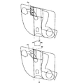
図3は、実施例3における車両のドア及び乗員を示した概略図である。図3(A)は通常時、図3(B)〜図3(D)は側面衝突時を表し、図3(A)の状態から車両が衝突物に側面衝突し、図3(B)、図3(C)、図3(D)の順に時間が経過している。 FIG. 3 is a schematic diagram illustrating a vehicle door and an occupant in the third embodiment. 3A shows a normal state, and FIGS. 3B to 3D show a side collision, and the vehicle collides with the collision object from the state of FIG. 3A, and FIG. Time elapses in the order of FIG. 3C and FIG.
図3(A)において、ドア4の車両内側にはシート(不図示)が配置され、該シートに乗員2が座るように構成されている。
ドア4は、車両の外板をなすアウタパネル10と、アウタパネル10の車両内側に配されてアウタパネル10とともにウインドガラス(不図示)、ドアロックシステム(不図示)等の収容空間を形成するインナパネル8と、インナパネル8の車両内側に取り付けられ内装品(不図示)が取り付けられるドアトリムとから構成されている。
また、視認性を向上させるためにドア4の上部に位置するドアガラス(不図示)を広くとると同時にベルトラインの高さ位置が下がり、乗員2が一般成人である場合には肩部Xがベルトラインよりも上方に位置するようなドア4構造となっている。
In FIG. 3A, a seat (not shown) is arranged on the vehicle inner side of the
The
Further, in order to improve the visibility, a wide door glass (not shown) located at the top of the
前記ドアトリムは、ドアトリム本体6と、上方移動部18とから構成されている。また、上方移動部18の下部に圧縮バネ14の上部が固定されており、該圧縮バネ14の下部はインナパネル8の上部に固定されている。上方移動部18に設けた突起状のストッパ20をインナパネル8に設けた嵌合孔に嵌合させることで前記圧縮バネ14が十分に圧縮された状態で、上方移動部18がドアトリム本体6の上部でドアトリム本体6と一体化するように固定されている。また、圧縮バネ14の軸心には車両上下方向に立設されたロッド状のガイド22が設けられている。
The door trim includes a door trim
前記ストッパ20にはワイヤケーブル26の一端が取り付けられており、ワイヤケーブル26の他端はワイヤ巻取り装置24に収納されている。
また、衝突検知センサ28が設けられている。衝突検知センサ28は車両の側面衝突を検知するものであり、実施例3に係る車両用ドア4専用に設けてもいいが、図2を用いて説明した実施例2における衝突検知センサと同様に、車両のBピラー内部に備えられた側面衝突を検知するセンサや、サイドエアバックを作動させるためのエアバックECUの衝突検知信号など、他の設備と兼用するものでもよい。
衝突検知センサ28とワイヤ巻取り装置24とはケーブルを介して接続されており、衝突検知センサ28で車両の側面衝突を検知すると前記ケーブルを介してワイヤ巻取り装置24に作動命令信号が送られ、ワイヤ巻取り装置24が作動してワイヤケーブル26を巻取るように構成されている。
One end of a
Further, a
The
さらに、上方移動部18とドアトリム本体6とは、ドアトリム本体6の上部で車幅方向にオーバーラップしており、上方移動部18とドアトリム本体6との間に出来る空間には車両前後方向に延びるEA部材16が上方移動部18に固定されて配置されている。
Further, the upper moving
図3(A)に示された構成のドア4の側面に衝突物30が衝突すると、図3(B)に示したように衝突による荷重の車両内側方向への入力によって、ドア4を構成するアウタパネル10が車両内側方向へ侵入する。この衝突を衝突検知センサ28が検知すると、図3(B)に示したようにケーブルを介してワイヤ巻取り装置24に作動命令信号が送られる。
前記作動命令信号を受けると、ワイヤ巻取り装置24はワイヤケーブル26を巻取る。これにより、ワイヤケーブル26のワイヤ巻取り装置24と反対側の端部に取り付けられたストッパ20がインナパネル8に設けた嵌合孔から引き抜かれる。
When the colliding
When receiving the operation command signal, the
ワイヤ巻取り装置24の作動によってストッパ20がインナパネル8に設けた嵌合孔から引き抜かれると、上方移動部18のインナパネル8への固定が解除されるため、図3(C)に示したように、圧縮バネ14の復元力によって上方移動部18及びEA部材16がガイド22に沿って乗員2の肩部Xの高さ位置と略同じ高さ位置まで上方に移動する。
When the
さらに衝突物30による荷重の入力が進むと、ドア4と乗員2が衝突するが、図3(D)に示したように、上方移動部18及びEA部材16が肩部Xと略同じ高さ位置まで移動しているため、衝突によるエネルギーが適切に人体耐性の高い肩部に伝達される。
さらに、図3(A)に示した通常時に上方移動部18及びEA部材16が位置していた場所は、上方移動部18及びEA部材16が上方に移動することによってスペースができるため、人体耐性の低い胸部への衝突によるエネルギーの伝達を低減することができる。このようにして出来るスペースで開くように車両の側面衝突時に作動するサイドエアバックを設けることもできる。
さらにまた、通常時は上方移動手段を定位置に固定し、側方からの荷重入力時には上方移動部18を上方へ移動させる火薬シリンダ15は、ドアトリム本体に覆われているため、前記移動手段と乗員とが直接衝突することを回避することができる。
When the input of the load by the colliding
Furthermore, the place where the
Furthermore, the
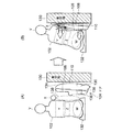
図1、図2及び図3を用いて説明した実施例1、2及び3におけるEA部材16の配置位置について図4を用いて説明する。
EA部材16は、車両の側面衝突時に肩部Xに位置していればよい。そのため、通常時は、図4左図に示したように、EA部材16はその高さ位置が肩部Xよりも低い位置に配置される。また、車両前後方向は、EA部材16の配置される範囲が肩部Xの車両前後方向よりも広い範囲となるように配置される。ドア4の後方からドア全体の1/3〜1/2程度の範囲にEA部材16を配置すればよい。このようなEA部材の配置により衝突時は図4右図に示したようにEA部材16が上方に移動し、肩部に衝突によるエネルギーを伝達することができる。
The arrangement position of the
The
ベルトラインが乗員の肩部よりも低い車両においても、車両の側面への衝突時に、人体耐性の高い肩部及び腰部へ衝突によるエネルギーを伝達し、衝突によって車両内側へ侵入してくるドアから乗員をいち早く遠ざけ、且つ人体耐性の低い胸部へのエネルギーの入力を低減するため胸部とドアとの間にスペースを確保することができる車両用ドアとして利用することができる。 Even in vehicles where the beltline is lower than the shoulder of the occupant, when the vehicle collides with the side of the vehicle, energy from the collision is transmitted to the shoulder and waist where the human body is highly resistant. Can be used as a vehicle door that can secure a space between the chest and the door in order to reduce the input of energy to the chest with low human body resistance.
2 乗員
4 ドア
6 ドアトリム本体
8 インナパネル
10 アウタパネル
12 プッシュロッド
14 圧縮バネ
15 アクチュエーター
16 エネルギー吸収材
18 上方移動部
20 ストッパ
22 ガイド
24 ワイヤ巻取り装置
26 ワイヤケーブル
28 衝突検知センサ
30 衝突物
2
Claims (6)
前記ドアトリムは、前記ドアパネルに固定されるドアトリム本体と、該ドアトリム本体と分割されて上方に移動可能な上方移動部とから構成され、
前記上方移動部とドアパネルとの間に、前記上方移動部とともに上方に移動可能な衝撃吸収材を収容し、
前記車両への側方からの荷重入力時に、前記上方移動部を前記衝撃吸収材とともに上方に移動させる移動手段を設けたことを特徴とする車両用ドア。 In a vehicle door comprising a vehicle door panel and a door trim attached to the interior side of the door panel,
The door trim is composed of a door trim main body fixed to the door panel, and an upper moving portion that is divided from the door trim main body and is movable upward.
Between the upper moving part and the door panel, a shock absorber that can move upward together with the upper moving part is accommodated,
A vehicle door comprising a moving means for moving the upper moving portion together with the shock absorber when a load is applied from the side to the vehicle.
前記移動手段は、
下部を前記インナパネルに固定され、上部を前記上方移動部に固定された圧縮バネと、
前記上方移動部に取り付けられた車両外側を向いた突起部と、
前記インナパネルに設けられ、前記突起部を嵌合可能な嵌合孔と、
前記突起部先端と対向する位置で、前記アウタパネルの車両内側に取り付けられたプッシュロッドとから構成され、
前記圧縮バネが弾性変形した状態で前記突起部を前記嵌合孔に嵌合させることで、前記上方移動部を前記インナパネルに固定し、
前記車両への側方からの荷重入力時に、該荷重により前記プッシュロッドが車両内側方向へ移動することで前記突起部を前記嵌合孔から外し、前記圧縮バネの復元力により前記上方移動部を上方へ移動させることを特徴とする請求項1乃至3のいずれか記載の車両用ドア。 In the door panel, an outer panel and an inner panel are arranged in order from the outdoor side,
The moving means is
A compression spring having a lower part fixed to the inner panel and an upper part fixed to the upward movement part;
A projecting portion facing the outside of the vehicle attached to the upward moving portion;
A fitting hole provided in the inner panel and capable of fitting the protrusion;
It is composed of a push rod attached to the inner side of the outer panel at a position facing the protrusion tip,
By fitting the protrusion in the fitting hole in a state where the compression spring is elastically deformed, the upper moving part is fixed to the inner panel,
When a load is input from the side to the vehicle, the push rod is moved toward the inside of the vehicle by the load so that the protrusion is removed from the fitting hole, and the upward moving portion is removed by the restoring force of the compression spring. 4. The vehicle door according to claim 1, wherein the vehicle door is moved upward.
前記車両への側方からの荷重入力を検知する検知手段と、
火薬の爆発によってシリンダ内のピストンを作動させる火薬シリンダから構成され、
前記火薬シリンダのシリンダを前記ドアパネルに固定するとともに、前記ピストンを前記上方移動部に固定し、
前記検知手段により車両への側方からの荷重入力を検知すると、前記火薬シリンダを作動させ、前記上方移動部を上方へ移動させることを特徴とする請求項1乃至3のいずれか記載の車両用ドア。 The moving means is
Detecting means for detecting a load input from a side to the vehicle;
It consists of a gunpowder cylinder that activates the piston in the cylinder by the explosion of gunpowder,
While fixing the cylinder of the gunpowder cylinder to the door panel, the piston is fixed to the upward movement part,
4. The vehicle according to claim 1, wherein when the load input from the side to the vehicle is detected by the detection unit, the gunpowder cylinder is operated to move the upward moving portion upward. 5. door.
前記車両への側方からの荷重入力を検知する検知手段と、
下部を前記ドアパネルに固定され、上部を前記上方移動部に固定された圧縮バネと、
前記上方移動部に設けられ車両外側を向いた突起部と、
前記ドアパネルに設けられ、前記突起部を嵌合可能な嵌合孔と、
前記突起部を嵌合穴から取り外し可能な取り外し手段とから構成され、
前記圧縮バネが弾性変形した状態で前記突起部を前記嵌合孔に嵌合させることで、前記上方移動部を前記ドアパネルに固定し、
前記検知手段により車両への側方からの荷重入力を検知すると、前記取り外し手段によって前記突起部を前記嵌合孔から外し、前記圧縮バネの復元力により前記上方移動部を上方へ移動させることを特徴とする請求項1乃至3のいずれか記載の車両用ドア。 The moving means is
Detecting means for detecting a load input from a side to the vehicle;
A compression spring having a lower part fixed to the door panel and an upper part fixed to the upward movement part;
A protrusion provided on the upward movement portion and facing the vehicle outside;
A fitting hole provided in the door panel and capable of fitting the protrusion;
The protrusion is composed of detachable means that can be removed from the fitting hole,
By fixing the projection to the fitting hole in a state where the compression spring is elastically deformed, the upper moving part is fixed to the door panel,
When the load input from the side to the vehicle is detected by the detection means, the protrusion is removed from the fitting hole by the removal means, and the upward movement portion is moved upward by the restoring force of the compression spring. The vehicle door according to any one of claims 1 to 3.
Priority Applications (1)
| Application Number | Priority Date | Filing Date | Title |
|---|---|---|---|
| JP2008326621A JP2010143555A (en) | 2008-12-22 | 2008-12-22 | Vehicular door |
Applications Claiming Priority (1)
| Application Number | Priority Date | Filing Date | Title |
|---|---|---|---|
| JP2008326621A JP2010143555A (en) | 2008-12-22 | 2008-12-22 | Vehicular door |
Publications (1)
| Publication Number | Publication Date |
|---|---|
| JP2010143555A true JP2010143555A (en) | 2010-07-01 |
Family
ID=42564416
Family Applications (1)
| Application Number | Title | Priority Date | Filing Date |
|---|---|---|---|
| JP2008326621A Withdrawn JP2010143555A (en) | 2008-12-22 | 2008-12-22 | Vehicular door |
Country Status (1)
| Country | Link |
|---|---|
| JP (1) | JP2010143555A (en) |
Cited By (3)
| Publication number | Priority date | Publication date | Assignee | Title |
|---|---|---|---|---|
| JP2012126315A (en) * | 2010-12-16 | 2012-07-05 | Mitsubishi Motors Corp | Door structure of vehicle |
| JP2018069956A (en) * | 2016-10-31 | 2018-05-10 | ダイハツ工業株式会社 | Vehicle structure |
| CN116215436A (en) * | 2023-04-21 | 2023-06-06 | 东风汽车有限公司东风日产乘用车公司 | Vehicle side air curtain mounting mechanism, control method, electronic device and storage medium |
-
2008
- 2008-12-22 JP JP2008326621A patent/JP2010143555A/en not_active Withdrawn
Cited By (4)
| Publication number | Priority date | Publication date | Assignee | Title |
|---|---|---|---|---|
| JP2012126315A (en) * | 2010-12-16 | 2012-07-05 | Mitsubishi Motors Corp | Door structure of vehicle |
| JP2018069956A (en) * | 2016-10-31 | 2018-05-10 | ダイハツ工業株式会社 | Vehicle structure |
| CN116215436A (en) * | 2023-04-21 | 2023-06-06 | 东风汽车有限公司东风日产乘用车公司 | Vehicle side air curtain mounting mechanism, control method, electronic device and storage medium |
| CN116215436B (en) * | 2023-04-21 | 2025-07-18 | 东风汽车有限公司东风日产乘用车公司 | Vehicle side air curtain mounting mechanism, control method, electronic device and storage medium |
Similar Documents
| Publication | Publication Date | Title |
|---|---|---|
| US6568743B1 (en) | Active armrest for side impact protection | |
| US8820830B2 (en) | Vehicle seat | |
| US8033356B2 (en) | External airbag system of vehicle | |
| KR102683790B1 (en) | Seat airbag for vehicle | |
| CN105774741A (en) | Airbag apparatus and vehicle equipped with same | |
| US7992894B2 (en) | Side airbag unit for vehicles | |
| JP5685755B2 (en) | Rear airbag device with improved safety performance | |
| WO2012111073A1 (en) | Occupant protection device | |
| JP2784322B2 (en) | Vehicle safety seat | |
| WO2016136339A1 (en) | Structure for side portion of vehicle body | |
| JPH0664491A (en) | Airbag device that protects occupants against side impacts | |
| KR20190019195A (en) | Airbag cushions for automotive airbag devices and airbag devices | |
| CN103906640A (en) | Vehicle side door structure and vehicle occupant protection system | |
| US20140207340A1 (en) | Adaptive crash structure for a vehicle and associated vehicle | |
| JP2010143555A (en) | Vehicular door | |
| JP5799985B2 (en) | Vehicle behavior control device | |
| JP2014184855A (en) | Far side occupant restraint device | |
| JP2010047209A (en) | Vehicular shock-absorbing member, and vehicular occupant crash protector | |
| WO2008065964A1 (en) | Curtain airbag device | |
| KR20240084981A (en) | Passenger protection device of door-mounted type and method for controlling the protection device | |
| JP2009516617A (en) | Safety system | |
| JP2006015855A (en) | Crew protection device | |
| KR101527027B1 (en) | Structure of seat for vehicle | |
| KR100794011B1 (en) | Guidance device for deployment of curtain airbag | |
| KR101593077B1 (en) | Airbag support assembly |
Legal Events
| Date | Code | Title | Description |
|---|---|---|---|
| A300 | Withdrawal of application because of no request for examination |
Free format text: JAPANESE INTERMEDIATE CODE: A300 Effective date: 20120306 |