JP2010143596A - Gear storing tray, and storing body - Google Patents
Gear storing tray, and storing body Download PDFInfo
- Publication number
- JP2010143596A JP2010143596A JP2008320797A JP2008320797A JP2010143596A JP 2010143596 A JP2010143596 A JP 2010143596A JP 2008320797 A JP2008320797 A JP 2008320797A JP 2008320797 A JP2008320797 A JP 2008320797A JP 2010143596 A JP2010143596 A JP 2010143596A
- Authority
- JP
- Japan
- Prior art keywords
- gear
- tray
- storage
- storage hole
- main body
- Prior art date
- Legal status (The legal status is an assumption and is not a legal conclusion. Google has not performed a legal analysis and makes no representation as to the accuracy of the status listed.)
- Granted
Links
- 238000003860 storage Methods 0.000 claims abstract description 219
- 230000002093 peripheral effect Effects 0.000 claims description 33
- 230000005484 gravity Effects 0.000 claims description 16
- 230000002265 prevention Effects 0.000 claims description 6
- 230000001105 regulatory effect Effects 0.000 claims description 5
- 230000007423 decrease Effects 0.000 claims description 2
- 230000008021 deposition Effects 0.000 abstract 1
- 230000002708 enhancing effect Effects 0.000 abstract 1
- 238000000034 method Methods 0.000 description 19
- 230000036544 posture Effects 0.000 description 7
- 238000010586 diagram Methods 0.000 description 6
- 230000004308 accommodation Effects 0.000 description 5
- 238000005461 lubrication Methods 0.000 description 5
- 230000033228 biological regulation Effects 0.000 description 4
- 239000000463 material Substances 0.000 description 3
- 239000000470 constituent Substances 0.000 description 2
- 230000000694 effects Effects 0.000 description 2
- 238000004806 packaging method and process Methods 0.000 description 2
- 230000006866 deterioration Effects 0.000 description 1
- 230000009191 jumping Effects 0.000 description 1
- 238000010030 laminating Methods 0.000 description 1
- 238000004519 manufacturing process Methods 0.000 description 1
- 238000012986 modification Methods 0.000 description 1
- 230000004048 modification Effects 0.000 description 1
- NJPPVKZQTLUDBO-UHFFFAOYSA-N novaluron Chemical compound C1=C(Cl)C(OC(F)(F)C(OC(F)(F)F)F)=CC=C1NC(=O)NC(=O)C1=C(F)C=CC=C1F NJPPVKZQTLUDBO-UHFFFAOYSA-N 0.000 description 1
- 238000006748 scratching Methods 0.000 description 1
- 230000002393 scratching effect Effects 0.000 description 1
- 230000035939 shock Effects 0.000 description 1
- 229920006300 shrink film Polymers 0.000 description 1
- 229920003002 synthetic resin Polymers 0.000 description 1
- 239000000057 synthetic resin Substances 0.000 description 1
Images




Landscapes
- Stackable Containers (AREA)
- Containers Having Bodies Formed In One Piece (AREA)
- Packaging Of Machine Parts And Wound Products (AREA)
- Packaging Of Annular Or Rod-Shaped Articles, Wearing Apparel, Cassettes, Or The Like (AREA)
- Packaging Frangible Articles (AREA)
Abstract
Description
本発明は、時計を構成する小型精密部品の1つである歯車を収納する歯車用収納トレー及びこれを備える収納体に関するものである。 The present invention relates to a gear storage tray for storing a gear, which is one of small precision parts constituting a timepiece, and a storage body including the same.
機械式時計に代表されるアナログ式の時計は、非常に小型で精密な歯車等の部品が無数に組み合わされて構成されている。特に、歯車は、動力を伝達するための重要な部品であるので、時計を組み立てるにあたり変形や傷等がつかないように取り扱いに注意を要する必要がある。
ところで、時計を組み立てる場合には、歯車等の各種の部品をそれぞれ部品毎に製作した後、組み立てラインに搬送(運送や輸送を含む)している。従って、部品の1つである歯車に関しても、製作場所から組み立てラインまで搬送する必要がある。
An analog timepiece represented by a mechanical timepiece is configured by countless combinations of extremely small and precise gears and the like. In particular, since the gear is an important part for transmitting power, it is necessary to handle it with care so as not to be deformed or scratched when the timepiece is assembled.
By the way, when assembling a timepiece, various parts such as gears are manufactured for each part and then conveyed to an assembly line (including transportation and transportation). Therefore, it is necessary to convey the gear which is one of the parts from the production place to the assembly line.
ここで、歯車を取り扱う方法としては、従来から以下のような方法が採用されている。
第1の方法としては、製作した歯車を一定の数量ずつまとめてプラスチック箱やビニール袋に入れた後、搬送する方法である。
第2の方法としては、製作した歯車を一定の数量ずつまとめて、空気で膨らませたビニール袋に入れた後、搬送する方法である。
第3の方法としては、複数の窪みが形成されたトレーを用意し、各窪みに歯車を1つずつ収納した後、トレーごと搬送する方法である。
第4の方法としては、空気で膨らませたビニール袋を複数用意し、各ビニール袋に歯車を1つずつ入れた後、搬送する方法である。
Here, as a method for handling the gear, the following method has been conventionally employed.
The first method is a method in which the manufactured gears are collected in a certain quantity and put into a plastic box or plastic bag and then transported.
The second method is a method in which a certain number of manufactured gears are put together in a plastic bag inflated with air and then transported.
As a third method, a tray in which a plurality of depressions are formed is prepared, one gear is stored in each depression, and then the whole tray is conveyed.
As a fourth method, a plurality of plastic bags inflated with air are prepared, and after one gear is put in each plastic bag, it is transported.
なお、これらの取り扱い方法は、作業者が経験に基づいて工夫しながら実際に行っている方法であるので、このような方法が記載された公知文献は現時点においては見つかっていないため開示できない。 Note that these handling methods are methods that are actually performed by an operator while devising based on experience. Therefore, publicly known documents in which such methods are described have not been found at the present time and cannot be disclosed.
しかしながら、上述した歯車の取り扱い方法には、まだ以下の課題が残されている。
はじめに、第1の方法の場合には、一定数量をまとめて扱うので、搬送中に歯車同士がぶつかったり、絡み合ったりしてしまい、変形や傷等が付き易いという問題があった。しかも、外部からの衝撃をうけた場合には、変形や傷が容易に付き易かった。
However, the following problems still remain in the gear handling method described above.
First, in the case of the first method, since a certain amount is handled collectively, there is a problem that the gears collide with each other or are entangled during conveyance, and are easily deformed or scratched. Moreover, when subjected to external impacts, deformation and scratches were easily made.
第2の方法の場合には、空気で膨らませたビニール袋に入れているので、外部からの衝撃には強いものの、同じビニール袋内に入れられている歯車同士が搬送中にぶつかったり、絡み合ったりしてしまう。そのため、やはり変形や傷が付き易いものであった。しかも、搬送後に、ビニール袋から歯車を取り出して、別のトレーや容器に一時的に移し替える手間が必要であった。 In the case of the second method, since it is put in a plastic bag inflated with air, it is strong against impact from the outside, but the gears put in the same plastic bag collide or get entangled during transportation. Resulting in. For this reason, it is still easy to be deformed and scratched. In addition, it is necessary to take the trouble of taking out the gear from the plastic bag and temporarily transferring it to another tray or container after transportation.
第3の方法の場合には、各窪みに歯車を1つずつ収納した状態で搬送できるので、歯車同士がぶつかったり、絡み合ったりする恐れがない。しかしながら、搬送中に揺れ等によって窪みの中で歯車が暴れ易く、これによって変形や傷が付く場合があった。しかも、暴れた際に、トレーの表面が削れて(擦れて)歯車に付着する可能性もあった。よって、異物の付着による品質低下を引き起こす可能性があった。
加えて、歯車が窪みの中でどのような姿勢になるか不明(姿勢がバラバラ)であるので、搬送後に歯車を摘んで窪みから取り上げる際に手間がかかってしまい、効率の良い作業を行うことができなかった。また、通常、組み立て前に歯車に対して注油を行うものであるが、窪みの中で歯車の姿勢がバラバラであるので、効率良く注油作業を行うことができなかった。
In the case of the third method, since the gears can be transported in a state where one gear is housed in each recess, there is no fear of the gears colliding with each other or being entangled with each other. However, the gears are likely to be violated in the depression due to shaking or the like during conveyance, which may cause deformation or scratches. In addition, there is a possibility that the surface of the tray is scraped (rubbed) and adheres to the gears when it goes wild. Therefore, there is a possibility of causing quality deterioration due to adhesion of foreign matter.
In addition, the posture of the gear in the recess is unknown (the posture is disjointed), so it takes time and effort to pick up the gear after picking up and take it out of the recess. I could not. In addition, the gears are usually lubricated before assembly, but the gears have different postures in the recesses, so the lubrication operation cannot be performed efficiently.
第4の方法の場合には、空気で膨らませたビニール袋の中に歯車を1つずつ入れるので、外部からの衝撃に強いだけでなく、歯車同士のぶつかりや絡み合いもない。そのため、変形や傷が付き難く、好ましい方法である。しかしながら、歯車を1つずつビニール袋に入れる必要があるので、この梱包に費やす手間がどうしてもかかってしまい作業性が悪かった。しかも、梱包するだけでなく、搬送後にビニール袋から取り出す手間もかかってしまううえ、別のトレーや容器に一時的に移し替える手間も必要であった。 In the case of the fourth method, since gears are put one by one in a plastic bag inflated with air, not only are they resistant to external impacts, but there is no collision or entanglement between gears. Therefore, it is a preferable method because it is difficult to be deformed or scratched. However, since it is necessary to put the gears one by one in a plastic bag, the work spent on the packaging is inevitably taken, and the workability is poor. In addition to packaging, it also takes time to remove from the plastic bag after transport, and also requires time to temporarily transfer to another tray or container.
本発明は、このような事情に考慮してなされたもので、その目的は、収納、搬送、組み立て時まで一貫して使用できるうえ、歯車を容易且つ速やかに、しかもがたつきを抑えながら決まった向きで収納することができ、異物の付着、変形や傷が付いてしまうことを未然に防止し、さらに摘み上げる作業性を格段に向上することができる歯車用収納トレーを提供することである。
また、別の目的としては、この歯車用収納トレーを備えた収納体を提供することである。
The present invention has been made in consideration of such circumstances, and its purpose can be used consistently from the time of storage, transport and assembly, and the gears are determined easily and quickly while suppressing rattling. It is possible to provide a gear storage tray that can be stored in a facing direction, prevent foreign matter from being attached, deformed, and scratched, and can further improve the picking up workability. .
Another object is to provide a storage body including the gear storage tray.
上記課題を解決するために、本発明は以下の手段を提案している。
本発明に係る歯車用収納トレーは、円板状の歯車本体、及び該歯車本体の中心に設けられた軸部を有し、重心が前記歯車本体から離間した前記軸部上にある歯車を収納する歯車用収納トレーであって、平板状のトレー本体と、前記トレー本体の少なくとも上面側に開口すると共に、前記上面側の開口端部の内径が前記歯車本体の直径よりも大きくなるように前記トレー本体に形成され、前記歯車を、該歯車の軸部が前記トレー本体の上下方向に沿った状態で収納する収納孔部と、を備え、前記収納孔部を画成する内周面の少なくとも一部には、上面側から下面側に向かうに連れて縮径すると共に、下端の内径が前記歯車本体の直径よりも小さいテーパ面が形成されていることを特徴とするものである。
In order to solve the above problems, the present invention proposes the following means.
The gear storage tray according to the present invention has a disc-shaped gear main body and a shaft portion provided at the center of the gear main body, and stores a gear whose center of gravity is on the shaft portion separated from the gear main body. A gear storage tray that opens to at least the upper surface side of the flat tray body and the tray body, and the inner diameter of the opening end on the upper surface side is larger than the diameter of the gear body. A storage hole formed in the tray main body and storing the gear in a state in which a shaft portion of the gear is along the vertical direction of the tray main body, and at least an inner peripheral surface defining the storage hole A part thereof is characterized in that a tapered surface is formed which is reduced in diameter from the upper surface side toward the lower surface side and whose inner diameter at the lower end is smaller than the diameter of the gear body.
本発明に係る歯車用収納トレーにおいて歯車を収納する際には、まず、この歯車用収納トレーを略水平な架台等の上に上面を上側にした状態で載置し、トレー本体の上下方向と鉛直方向とを略一致させる。
次いで、収納する歯車を把持し、この歯車を収納孔部に、この収納孔部の上面側の開口端部から挿入する。この際、歯車を、軸部において重心が位置する側(以下、一方側と称する)の端部から収納孔部に挿入する。その後、把持を解除することで、歯車は収納孔部内を下面側に向けて進入する。この際、歯車は、重心が位置する軸部の一方側における端部から挿入されているので、この軸部の一方側の端部や歯車本体の外周縁部が収納孔部を画成する内周面と接触することで、軸部の延在方向が鉛直方向、つまりトレー本体の上下方向と一致するように姿勢が矯正される。そして、歯車は、軸部の一方側の端部が鉛直下側、つまり下面側を向くようにして収納孔部内を進入する。
When storing gears in the gear storage tray according to the present invention, first, the gear storage tray is placed on a substantially horizontal base or the like with the upper surface facing upward, The vertical direction is substantially matched.
Next, the gear to be accommodated is gripped, and the gear is inserted into the accommodation hole from the opening end on the upper surface side of the accommodation hole. At this time, the gear is inserted into the housing hole from the end of the shaft portion where the center of gravity is located (hereinafter referred to as one side). Then, by releasing the grip, the gear enters the storage hole toward the lower surface side. At this time, since the gear is inserted from the end portion on one side of the shaft portion where the center of gravity is located, the end portion on one side of the shaft portion and the outer peripheral edge portion of the gear body define the housing hole portion. By contacting the peripheral surface, the posture is corrected so that the extending direction of the shaft portion matches the vertical direction, that is, the vertical direction of the tray body. Then, the gear enters the storage hole so that one end of the shaft portion faces vertically downward, that is, the lower surface.
ここで、収納孔部を画成する内周面の一部には、上面側から下面側に向かうに連れて縮径すると共に、下端の内径が歯車本体の直径より小さいテーパ面が形成されている。このため、歯車は、収納孔部内を下面側に向けて進入する過程で、テーパ面において内径が歯車本体の直径と同等である部分まで歯車本体が進入したときに、テーパ面に歯車本体の外周縁部の下端が当接して支持され、下面側に向けた移動が規制される。この際、歯車は、歯車本体よりも重心が下面側に位置した状態で移動が規制されるので、姿勢が安定し、がたつきが抑えられる。これにより、歯車を、歯車本体を挟んで一方側とは反対側の他方側を上面側に向けた状態で収納孔部に収納することができる。
以上に示したようにこの歯車用収納トレーによれば、歯車を単に収納孔部に挿入するだけの容易な作業で速やかに、しかもがたつきを抑えながら決まった向きで収納することができる。
Here, a part of the inner peripheral surface that defines the storage hole portion is formed with a tapered surface that is reduced in diameter from the upper surface side toward the lower surface side, and that the inner diameter of the lower end is smaller than the diameter of the gear body. Yes. For this reason, when the gear body enters the portion where the inner diameter is equal to the diameter of the gear body in the taper surface in the process of entering the inside of the housing hole toward the lower surface side, the outer surface of the gear body enters the taper surface. The lower end of the peripheral edge abuts and is supported, and movement toward the lower surface side is restricted. At this time, since the movement of the gear is restricted in a state where the center of gravity is located on the lower surface side with respect to the gear main body, the posture is stabilized and rattling is suppressed. As a result, the gear can be stored in the storage hole with the other side opposite to the one side facing the gear body facing the upper surface.
As described above, according to the gear storage tray, it is possible to store the gears in a fixed direction quickly and easily with a simple operation of simply inserting the gears into the storage holes.
また、この歯車用収納トレーにおいて歯車を搬送する際には、前述のように歯車ががたつきを抑えられながら収納されているので、仮に外部から衝撃を受けた場合であっても歯車が暴れることを抑制することが可能となり、歯車に傷が付くことや歯車の変形、及びトレー本体の表面が擦れることに起因する異物の付着等を未然に防止することができる。
また、この歯車用収納トレーにおいて歯車を搬送後、この歯車を用いて組み立てを行う際には、前述のように歯車ががたつきを抑えられながら決まった向きで収納されているので、搬送後であっても歯車を他方側を上面側に向けた状態で収納孔部に収納させておくことが可能となり、歯車を摘み上げる作業性を格段に向上することができる。なお、歯車において他方側に位置する部分に注油作業を行う場合は、この注油作業を歯車を収納孔部に収納した状態で行うことが可能となり、作業性をより一層向上することができる。
以上に示したように、この歯車用収納トレーによれば、収納、搬送、組み立て時まで取り出し作業を行う必要が無く、一貫して使用することができる。
Further, when the gears are transported in the gear storage tray, the gears are stored while suppressing rattling as described above. This makes it possible to prevent damage to the gears, deformation of the gears, and adhesion of foreign matters due to rubbing of the surface of the tray body.
Also, when assembling with this gear after transporting the gears in this gear storage tray, the gears are stored in a fixed direction while suppressing rattling as described above. Even so, the gear can be stored in the storage hole with the other side facing the upper surface, and the workability of picking up the gear can be significantly improved. In addition, when performing the lubrication operation | work to the part located in the other side in a gearwheel, it becomes possible to perform this lubrication operation | work in the state which accommodated the gearwheel in the accommodation hole part, and workability | operativity can be improved further.
As described above, according to the gear storage tray, it is not necessary to perform the take-out operation until storage, transport, and assembly, and can be used consistently.
また、前記収納孔部を画成する内周面には、前記テーパ面の下端に連なると共に、該下端の内径と前記上下方向によらず内径が同等な規制面が形成されていても良い。 The inner peripheral surface that defines the storage hole may be formed with a regulation surface that is continuous with the lower end of the tapered surface and that has the same inner diameter regardless of the inner diameter of the lower end and the vertical direction.
この場合、収納孔部に歯車が収納された際に、軸部の一方側の端部が規制面で画成される空間内に挿入されることで、仮に収納孔部内で歯車ががたついたとしても、軸部が規制面に接触して歯車のがたつきをより確実に抑制することができる。 In this case, when the gear is stored in the storage hole, the end of the one side of the shaft portion is inserted into the space defined by the restriction surface, so that the gear is rattled in the storage hole. Even so, the shank of the gear can be more reliably suppressed by the shaft portion coming into contact with the regulating surface.
また、前記収納孔部は、有底状に形成されていても良い。 Further, the storage hole may be formed in a bottomed shape.
この場合、収納孔部が有底状に形成されているので、トレー本体の下面側から異物等が入り込むのを抑制することが可能となり、歯車に異物が付着するのをより確実に防止することができる。 In this case, since the storage hole is formed in a bottomed shape, it is possible to prevent foreign matter from entering from the lower surface side of the tray body, and more reliably prevent foreign matter from adhering to the gear. Can do.
また、前記収納孔部は、前記テーパ面において内径が前記歯車本体の直径と一致する位置から底面までの前記上下方向に沿った大きさが、前記歯車の軸部において重心が位置する方向に延在する該軸部の長さより大きくなるように形成されていても良い。 In addition, the storage hole has a size along the vertical direction from the position where the inner diameter matches the diameter of the gear body on the tapered surface to the bottom surface, and extends in the direction in which the center of gravity is located at the shaft of the gear. You may form so that it may become larger than the length of this shaft part which exists.
この場合、テーパ面において内径が歯車本体の直径と一致する位置から底面までの上下方向に沿った大きさが、歯車の軸部において重心が位置する方向、つまり一方側に延在する軸部の長さより大きくなっているので、収納孔部に歯車が収納された際に、歯車の軸部の一方側の端部が収納孔部の底面に接触することがない。従って、歯車の変形や歯車に傷が付いてしまうのをより確実に防止することができる。 In this case, the size along the vertical direction from the position where the inner diameter matches the diameter of the gear body to the bottom surface on the tapered surface is the direction in which the center of gravity is located in the shaft portion of the gear, that is, the shaft portion extending to one side. Since it is larger than the length, when the gear is stored in the storage hole, the end on one side of the shaft portion of the gear does not contact the bottom surface of the storage hole. Accordingly, it is possible to more reliably prevent the gear from being deformed and the gear from being damaged.
また、前記トレー本体の下面において前記収納孔部と対応する位置には、前記歯車本体の直径よりも内径が小さい軸逃げ用凹部が形成され、この歯車用収納トレー同士を予め決められた向きで重ね合わせるときに、上段側トレーの前記軸逃げ用凹部が下段側トレーの前記収納孔部と対向して配置されるように両トレーを位置決めする位置決め機構を備えていても良い。 A shaft escape recess having an inner diameter smaller than the diameter of the gear body is formed at a position corresponding to the storage hole on the lower surface of the tray body, and the gear storage trays are arranged in a predetermined direction. There may be provided a positioning mechanism for positioning both trays so that the shaft escape recess of the upper tray faces the storage hole of the lower tray when overlapping.
この場合、歯車用収納トレー同士を重ね合わせることで、搬送時等に外部から衝撃を受けた場合であっても、収納孔部から上面側に向けて歯車が飛び出してしまうのを抑制することができる。加えて、歯車用収納トレー同士を重ね合わせることで、歯車の搬送時に一度に搬送する歯車用収納トレーの数を増やすことが可能となり、歯車の搬送効率を向上することができる。
しかも、歯車用収納トレー同士を重ね合わせるときに、位置決め機構によって、上段側トレーの軸逃げ用凹部が下段側トレーの収納孔部と対向して配置されるように両トレーを位置決めすることができる。従って、収納孔部に歯車を収納した際、仮にトレー本体の上面から歯車の軸部が突出するような場合であっても、軸部を上段側トレーの軸逃げ用凹部に収納することが可能となり、軸部が上段側トレーの下面に接触するのを防ぐことができる。よって、歯車の変形や歯車に傷が付いてしまうのを確実に防止することができる。
In this case, by superimposing the gear storage trays, it is possible to prevent the gears from popping out from the storage hole toward the upper surface side even when receiving an impact from the outside during transport or the like. it can. In addition, by superimposing the gear storage trays, it is possible to increase the number of gear storage trays transported at a time when the gears are transported, and to improve the gear transport efficiency.
In addition, when the gear storage trays are overlapped with each other, both trays can be positioned by the positioning mechanism such that the shaft escape recess of the upper tray is disposed opposite to the storage hole of the lower tray. . Therefore, when the gear is stored in the storage hole, even if the shaft portion of the gear protrudes from the upper surface of the tray body, the shaft portion can be stored in the shaft escape recess of the upper tray. Thus, the shaft portion can be prevented from contacting the lower surface of the upper tray. Therefore, it is possible to reliably prevent the gear from being deformed and the gear from being damaged.
また、前記位置決め機構は、前記トレー本体の上面における外周縁部に上側に向けて突設された位置決め凸部と、前記トレー本体の下面における外周縁部に下側に向けて開口され、前記位置決め凸部と係合される位置決め凹溝と、を備えていても良い。 The positioning mechanism includes a positioning convex portion projecting upward from an outer peripheral edge portion of the upper surface of the tray body, and an opening facing downward from an outer peripheral edge portion of the lower surface of the tray body. A positioning groove that is engaged with the convex portion may be provided.
この場合、位置決め機構によって位置決めする際に、単に位置決め凸部と位置決め凹溝とを係合するだけなので、位置決め作業を容易に行うことができる。
また、位置決め凸部がトレー本体の下面でなく上面に形成されているので、歯車用収納トレーを下面を下側にして架台等に載置する際に、位置決め機構を起因としてこの載置が阻害されることがない。
また、位置決め凸部及び位置決め凹溝のいずれもトレー本体の外周縁部に設けられているので、トレー本体における収納孔部のレイアウト性を向上することができる。例えば、収納孔部を複数形成する場合には、収納孔部の数をできるだけ増やすようにレイアウトすることが可能となる。
In this case, when positioning is performed by the positioning mechanism, the positioning convex portion and the positioning concave groove are merely engaged, so that the positioning operation can be easily performed.
In addition, since the positioning convex part is formed on the upper surface, not the lower surface of the tray body, when the gear storage tray is mounted on a pedestal or the like with the lower surface facing down, this mounting is hindered due to the positioning mechanism. It will not be done.
Further, since both the positioning convex portion and the positioning concave groove are provided on the outer peripheral edge portion of the tray main body, the layout property of the storage hole portion in the tray main body can be improved. For example, when a plurality of storage holes are formed, it is possible to lay out so as to increase the number of storage holes as much as possible.
また、前記上段側トレーの下面と前記下段側トレーの上面とが予め決められた向きと異なる向きで重ね合わせられようとしたときに、前記上段側トレーの下面と前記下段側トレーの上面との接触を防止する誤位置決め防止機構を備えていても良い。 Further, when the lower surface of the upper tray and the upper surface of the lower tray are to be overlapped in a direction different from a predetermined direction, the lower surface of the upper tray and the upper surface of the lower tray You may provide the mispositioning prevention mechanism which prevents a contact.
この場合、誤位置決め防止機構によって、上段側トレーの下面と下段側トレーの上面とが予め決められた向きと異なる向きで重ね合わせられようとしたときに、上段側トレーの下面と下段側トレーの上面との接触を防止することができる。従って、収納孔部に歯車を収納した際、仮にトレー本体の上面から歯車の軸部が突出しているような場合であっても、上段側トレーと下段側トレーとの位置決め方向を誤って重ね合わせようとした際に、軸部が上段側トレーの下面に接触してしまうのを防ぐことができる。よって、歯車の変形や歯車に傷が付いてしまうのを確実に防止することができる。 In this case, when the mispositioning prevention mechanism tries to overlap the lower surface of the upper tray and the upper surface of the lower tray in a direction different from the predetermined direction, the lower surface of the upper tray and the lower tray Contact with the upper surface can be prevented. Therefore, when the gear is stored in the storage hole, even if the gear shaft protrudes from the upper surface of the tray body, the positioning direction of the upper tray and the lower tray is mistakenly overlapped. When trying to do so, it is possible to prevent the shaft portion from coming into contact with the lower surface of the upper tray. Therefore, it is possible to reliably prevent the gear from being deformed and the gear from being damaged.
また、前記トレー本体には、重ね合わせる際の向きを認識するための目印が形成されていても良い。 The tray main body may be formed with a mark for recognizing the direction in which the tray is overlapped.
この場合、トレー本体に方向認識用の目印が形成されているので、手動或いはロボット等の機械で歯車用収納トレー同士を重ね合わせる際に、向きを間違えることなく両トレーを確実に予め決められた向きで重ね合わせることができる。従って、重ね合わせ作業をより効率良く行うことができる。なお、ロボット等の機械で重ね合わせ作業を行う場合には、目印を指標としてプログラミングできるので、制御が非常に容易になる。 In this case, since the direction recognition mark is formed on the tray body, both trays are surely determined in advance without making a mistake in the orientation when the gear storage trays are overlapped with each other manually or with a machine such as a robot. Can be overlapped in the direction. Therefore, the overlaying operation can be performed more efficiently. In addition, when performing a superposition operation with a machine such as a robot, since the mark can be programmed as an index, control becomes very easy.
また、前記収納孔部は、複数設けられていても良い。 In addition, a plurality of the storage holes may be provided.
この場合、収納孔部が複数設けられているので、一度に複数の歯車を収納及び搬送することが可能となる。しかも、一定量をまとめて取り扱う場合と異なり、搬送中に歯車同士がぶつかったり、絡み合ったりすることがないので、歯車の変形や歯車に傷が付いてしまうのを確実に防止することができる。 In this case, since a plurality of storage holes are provided, a plurality of gears can be stored and transported at a time. In addition, unlike a case where a certain amount is handled collectively, the gears do not collide with each other or are entangled during conveyance, so that it is possible to reliably prevent the gears from being deformed and the gears from being damaged.
また、本発明に係る収納体は、前記本発明に係る歯車用収納トレーと、円板状の歯車本体、及び該歯車本体の中心に設けられた軸部を有し、重心が前記歯車本体から離間した前記軸部上にあると共に、前記歯車用収納トレーの前記収納孔部に収納された歯車と、を備えていることを特徴とするものである。 Further, the storage body according to the present invention includes the gear storage tray according to the present invention, a disc-shaped gear body, and a shaft portion provided at the center of the gear body, and the center of gravity is from the gear body. And a gear housed in the housing hole portion of the gear housing tray, the shaft being on the spaced apart shaft portion.
本発明に係る収納体によれば、搬送、組み立て時まで一貫して使用できるうえ、歯車への異物の付着、歯車の変形や歯車に傷が付いてしまうことを未然に防止し、さらに歯車を摘み上げる作業性を格段に向上することができる。 According to the storage body of the present invention, it can be used consistently until conveyance and assembly, and it prevents the adhesion of foreign matter to the gear, deformation of the gear and damage to the gear, Workability to pick up can be remarkably improved.
本発明に係る歯車用収納トレーによれば、収納、搬送、組み立て時まで一貫して使用できるうえ、歯車を容易且つ速やかに、しかもがたつきを抑えながら決まった向きで収納することができ、異物の付着、変形や傷が付いてしまうことを未然に防止し、さらに摘み上げる作業性を格段に向上することができる。
また、本発明に係る収容体によれば、搬送、組み立て時まで一貫して使用できるうえ、歯車への異物の付着、歯車の変形や歯車に傷が付いてしまうことを未然に防止し、さらに歯車を摘み上げる作業性を格段に向上することができる。
According to the storage tray for gears according to the present invention, it can be used consistently until storing, transporting, assembling, and the gear can be stored in a fixed direction easily and quickly while suppressing rattling, It is possible to prevent foreign matter from being attached, deformed or scratched, and to further improve the picking workability.
In addition, according to the container according to the present invention, it can be used consistently until the time of transportation and assembly, and prevents foreign matter from adhering to the gear, deformation of the gear and scratching of the gear. The workability of picking up the gear can be remarkably improved.
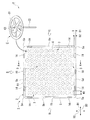
以下、本発明に係る歯車用収納トレーの一実施形態を、図1から図16を参照して説明する。図1は、本発明に係る歯車用収納トレーの一実施形態の構成図である。図2(a)は、図1に示す歯車用収納トレーに収納する歯車を示す側面図である。図2(b)は、図1に示す歯車用収納トレーに収納する歯車を示す平面図である。
本実施形態の歯車用収納トレー1は、図1に示すように、円板状の歯車本体C1、及び該歯車本体C1の中心に設けられた軸部C2を有し、重心が歯車本体C1から離間した軸部C2上にある歯車Cを収納するものである。なお、歯車用収納トレー1に歯車Cが収納されると、収納パッケージ(収納体)Pとなる。
Hereinafter, an embodiment of a gear storage tray according to the present invention will be described with reference to FIGS. FIG. 1 is a configuration diagram of an embodiment of a gear storage tray according to the present invention. Fig.2 (a) is a side view which shows the gear accommodated in the storage tray for gears shown in FIG. FIG. 2B is a plan view showing gears stored in the gear storage tray shown in FIG.
As shown in FIG. 1, the
ここで、歯車Cについて簡単に説明する。本実施形態では、図2(a)及び図2(b)に示すように、歯車Cは、前記歯車本体C1と、該歯車本体C1をその厚み方向に貫通するように延在する前記軸部C2と、軸部C2の延在方向に沿って歯車本体C1に対して一方側に位置する軸部C2に連結されたハートカムC3と、を備えており、例えば機械式クロノグラフに用いる歯車等に採用されるものである。この歯車Cは、軸部C2の全長が例えば10mmと極めて微小であり、更にこの歯車Cには、内部に図示しないバネ等が収容されており、取り扱いに細心の注意が必要とされる。 Here, the gear C will be briefly described. In the present embodiment, as shown in FIGS. 2A and 2B, the gear C includes the gear body C1 and the shaft portion that extends through the gear body C1 in the thickness direction. C2 and a heart cam C3 connected to a shaft portion C2 located on one side with respect to the gear body C1 along the extending direction of the shaft portion C2, for example, a gear used for a mechanical chronograph, etc. It is adopted. In this gear C, the total length of the shaft portion C2 is as extremely small as 10 mm, for example, and a spring (not shown) or the like is accommodated in the gear C, and careful handling is required.
以下では、図2(a)に示すように、軸部C2の延在方向に沿って歯車本体C1に対してハートカムC3が位置する側(前記一方側)を歯車上側と称し、軸部C2の延在方向に沿って歯車本体C1を挟んで反対側を歯車下側と称する。また、歯車本体C1から歯車下側へ向けた軸部C2の長さ(突出量)をL1、歯車本体C1から歯車上側へ向けた軸部C2の長さ(突出量)をL2、軸部C2の延在方向に沿った歯車本体C1の大きさ(厚み)をL3、歯車本体C1における歯車上側の面からハートカムC3における歯車上側の面までの軸部C2の延在方向に沿った大きさをL4とする。 In the following, as shown in FIG. 2A, the side where the heart cam C3 is positioned with respect to the gear body C1 along the extending direction of the shaft portion C2 (the one side) is referred to as the gear upper side, and the shaft portion C2 The opposite side across the gear body C1 along the extending direction is referred to as the gear lower side. Further, the length (projection amount) of the shaft portion C2 from the gear body C1 to the lower side of the gear is L1, the length (projection amount) of the shaft portion C2 from the gear body C1 to the upper side of the gear is L2, and the shaft portion C2. The size (thickness) of the gear main body C1 along the extending direction of L3 is L3, and the size along the extending direction of the shaft portion C2 from the gear upper surface of the gear main body C1 to the gear upper surface of the heart cam C3. Let L4.
また、歯車Cの重心は、歯車本体C1から歯車下側に離間した軸部C2上にあるものとし、軸部C2は、前記長さL1と前記長さL2との関係がL1>L2であるものとする。更に、図2(a)に示すように、歯車本体C1の直径をW1とする。
なお、本実施形態に示す歯車Cは一例であって、歯車用収納トレー1に収納される歯車は上述したものに限られるものではなく、歯車本体及び軸部を有し、重心が歯車本体から離間した軸部上にあるものであれば良い。
Further, the center of gravity of the gear C is assumed to be on a shaft portion C2 spaced from the gear body C1 to the gear lower side, and the shaft portion C2 has a relationship between the length L1 and the length L2 such that L1> L2. Shall. Further, as shown in FIG. 2A, the diameter of the gear body C1 is W1.
The gear C shown in the present embodiment is an example, and the gears stored in the
図1に示すように、歯車用収納トレー1は、平板状のトレー本体2と、トレー本体2に形成され、歯車Cを、該歯車Cの軸部C2がトレー本体2の上下方向D1に沿った状態で収納する収納孔部3と、を備えている。
トレー本体2は、例えばいわゆるプラスチック等の合成樹脂で形成されると共に、表面が平滑となっており、図示の例では、外周縁部5における4つの角部5eがそれぞれ面取り(R加工)された平面視正方形状に形成されている。なお、トレー本体2の材質は、前述したものに限られない。
As shown in FIG. 1, the
The
収納孔部3は、トレー本体2の少なくとも上面4側に開口すると共に、上面4側の開口端部3a(図4参照)の内径W2が歯車本体C1の直径W1よりも大きくなるように形成されている。また、図1に示すように、図示の例では、収納孔部3は、トレー本体2に複数(100個)形成されており、つまり歯車用収納トレー1には、複数(100個)の歯車Cを収納することができる。
The
なお、100個の収納孔部3は、平面視千鳥状になるように配置されている。図示の例では、平面視においてトレー本体2の外周縁の所定の一辺が延在する延在方向に沿う縦方向D2に10個整列してなる収納孔部3の列が、前記縦方向D2と直交する横方向D3に互いに等間隔あけた状態で10列隣接して配置されている。更に、前記収納孔部3の列は、隣接する列同士が前記縦方向D2の一方側及び他方側に交互に等間隔ずらされて配置されている。これにより、100個の収納孔部3は、平面視千鳥状をなしている。
The 100
以上のように配列されることで、トレー本体2における収納孔部3の配置は、平面視で線対称でなく、且つ平面視で点対称となっている。また、図示の例では、収納孔部3は、トレー本体2の外周縁部5を回避するように、平面視においてトレー本体2の上面4の外周縁の各辺から所定の距離B1だけトレー本体2の内側に離れてなる平面視矩形状の上面中央領域R1内に形成されている。なお、図示の例では、トレー本体2の外周縁の一辺の長さと、前記距離B1との比は、例えば21:1となっている。
By arranging as described above, the arrangement of the
図3は、図1に示す断面矢視A−A図である。図4は、図3に示す断面図の部分拡大図である。
図3及び図4に示すように、収納孔部3を画成する内周面6の少なくとも一部には、上面4側から下面7側に向かうに連れて縮径すると共に、下端の内径W3が歯車本体C1の直径W1よりも小さいテーパ面8が形成されている。また、本実施形態では、収納孔部3を画成する内周面6には、テーパ面8の下端に連なると共に、該下端の内径W3と前記上下方向D1によらず内径が同等な規制面9が形成されている。更に、本実施形態では、収納孔部3は、有底状に形成されている。
3 is a cross-sectional view taken along the line AA in FIG. 4 is a partially enlarged view of the cross-sectional view shown in FIG.
As shown in FIGS. 3 and 4, at least a part of the inner
図4に示すように、図示の例では、テーパ面8は、トレー本体2の上面4に連なるように形成されており、つまりテーパ面8の上端の内径はW2となっている。また、テーパ面8は、上面4側から下面7側に向かうに連れて漸次縮径しており、その縦断面視形状が傾斜平面となっている。これにより、この傾斜平面において前記上下方向D1の中間部分8aの内径が、歯車本体C1の直径W1と等しくなっている。
また、図示の例では、収納孔部3の底面10は、前記上下方向D1に直交する平坦面に形成されると共に、その外周縁が規制面9の下端に連なっている。
As shown in FIG. 4, in the illustrated example, the
In the illustrated example, the
また、図示の例では、収納孔部3において前記上下方向D1でテーパ面8の上端から下端までの範囲に位置する空間である円錐台状の空間S1と、収納孔部3において前記上下方向D1で規制面9の上端から下端までの範囲に位置する空間である円柱状の空間S2とは、各空間S1、S2における前記上下方向D1に沿った中心軸線が共通軸となっている。
また、図示の例では、前述した内径W2と内径W3との比は、例えばW2:W3=6:1となっている。また、テーパ面8の上端から下端までの前記上下方向D1に沿った大きさと、規制面9の上端から下端までの前記上下方向D1に沿った大きさとの比は、例えば3:1となっている。
Further, in the illustrated example, a truncated cone-shaped space S1 that is a space located in the range from the upper end to the lower end of the tapered
In the illustrated example, the ratio of the inner diameter W2 to the inner diameter W3 described above is, for example, W2: W3 = 6: 1. The ratio of the size along the vertical direction D1 from the upper end to the lower end of the tapered
また、図2及び図4に示すように、本実施形態では、収納孔部3は、テーパ面8における前記中間部分8aから底面10までの前記上下方向D1に沿った大きさL5が、歯車Cの軸部C2における歯車下側の長さL1より大きくなるように形成されている。また、図示の例では、収納孔部3は、テーパ面8における前記中間部分8aからテーパ面8の下端までの前記上下方向D1に沿った大きさL6が、歯車Cの軸部C2における歯車下側の長さL1より小さくなるように形成されている(即ち、L6<L1<L5)。
Further, as shown in FIGS. 2 and 4, in the present embodiment, the
また、図示の例では、収納孔部3は、テーパ面8における前記中間部分8aから上面4側の開口端部3aまでの前記上下方向D1に沿った大きさL7が、歯車本体C1の厚みL3と、歯車本体C1における歯車上側の面からハートカムC3における歯車上側の面までの大きさL4とを足した大きさより大きくなるように形成されている。更に、収納孔部3は、前記大きさL7が、歯車Cの軸部C2における歯車上側の長さL2と、歯車本体C1の厚みL3とを足した大きさよりも小さくなるように形成されている(即ち、L3+L4<L7<L2+L3)。
In the illustrated example, the
図5は、図1に示す歯車用収納トレーを下面側から見た平面図である。
図3から図5に示すように、本実施形態では、トレー本体2の下面7において収納孔部3と対応する位置には、歯車本体C1の直径W1よりも内径W4が小さい軸逃げ用凹部11が形成されている。図4に示すように、図示の例では、軸逃げ用凹部11は、トレー本体2の下面7において収納孔部3の下側に位置する部分に形成されている。
FIG. 5 is a plan view of the gear storage tray shown in FIG. 1 as viewed from the lower surface side.
As shown in FIGS. 3 to 5, in this embodiment, the
また、図4及び図5に示すように、図示の例では、軸逃げ用凹部11は、内部の空間S3が円柱状になるように形成されている。更に、図4に示すように、軸逃げ用凹部11は、前記空間S3における前記上下方向D1に沿った中心軸線が、収納孔部3における前記各空間S1、S2の前記共通軸と同軸になるように形成されている。また、軸逃げ用凹部11の前記上下方向D1に沿った大きさ(深さ)は、L8となっている(但し、L8>L2+L3−L7)。
As shown in FIGS. 4 and 5, in the illustrated example, the
以上のように形成された軸逃げ用凹部11は、図5に示すように、トレー本体2の下面7において平面視千鳥状に配置される。この軸逃げ用凹部11は、トレー本体2の下面7において前記上面中央領域R1に対応する領域、つまり平面視においてトレー本体2の下面7の外周縁の各辺から所定の距離B1だけトレー本体2の内側に離れてなる平面視矩形状の下面中央領域R2内に形成されている。
The shaft escape recesses 11 formed as described above are arranged in a zigzag shape in a plan view on the
また、図5に示すように、図示の例では、トレー本体2の下面7には、肉抜き部12が複数形成されている。肉抜き部12は、軸逃げ用凹部11が前記下面中央領域R2内において平面視千鳥状に配置されることで前記下面中央領域R2内において軸逃げ用凹部11間に生ずる隙間領域に形成されている。図3及び図5に示すように、図示の例では、各肉抜き部12は、平面視長穴状の溝となっており、複数(100個)の肉抜き部12は、平面視千鳥状になるように配置されている。この肉抜き部12を設けることで、歯車用収納トレー1に用いる材料を低減して、歯車用収納トレー1の低コスト化を図ることができる。
Further, as shown in FIG. 5, in the illustrated example, a plurality of lightening
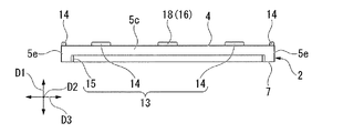
図6は、図1に示す矢視B図である。図7は、図1に示す矢視C図である。図8は、図1に示す矢視D図である。
図6から図8に示すように、本実施形態では、歯車用収納トレー1は、この歯車用収納トレー1同士を後述する予め決められた向きで重ね合わせるときに、上段側トレー1の軸逃げ用凹部11が下段側トレー1の収納孔部3と対向して配置されるように両トレー1、1を位置決めする位置決め機構13を備えている。
6 is an arrow B view shown in FIG. FIG. 7 is an arrow C view shown in FIG. FIG. 8 is an arrow D view shown in FIG.
As shown in FIGS. 6 to 8, in this embodiment, the
更に本実施形態では、位置決め機構13は、トレー本体2の上面4における外周縁部5に上側に向けて突設された位置決め凸部14と、トレー本体2の下面7における外周縁部5に下側に向けて開口され、位置決め凸部14と係合される位置決め凹溝15と、を備えている。
図1及び図5から図8に示すように、図示の例では、位置決め凸部14及び位置決め凹溝15は、トレー本体2における外周縁部5である4つの辺部5a、5b、5c、5dにそれぞれ形成されている。なお、本実施形態では、外周縁部5とは、前記各辺部5a、5b、5c、5dと、前記4つの角部5eと、を備えるものである。
Furthermore, in the present embodiment, the
As shown in FIGS. 1 and 5 to 8, in the illustrated example, the positioning
図1に示すように、位置決め凸部14は、各辺部5a、5b、5c、5dにそれぞれ2つずつ形成されており、全ての位置決め凸部14は同形同大となっている。位置決め凸部14は、その位置決め凸部14が形成されている辺部5a、5b、5c、5dの延在方向に沿って延びると共に、その延在方向の両端部が面取り(R加工)されて形成されている。
As shown in FIG. 1, two positioning
また、位置決め凸部14においてその延在方向に沿った大きさである長さは、収納孔部3の上面4側の開口端部3aの内径W2と略同等であり、前記延在方向に直交する方向に沿った大きさである幅は、B2(但し、B2<B1)となっている。また、図6に示すように、位置決め凸部14の突出高さ(トレー本体2の上面4から上端までの前記上下方向D1に沿った大きさ)は、B3となっている。
The length of the positioning
また、図6から図8に示すように、各辺部5a、5b、5c、5dにおける2つの位置決め凸部14は、各辺部5a、5b、5c、5dにおける延在方向の中点からの距離がそれぞれ等しくなるように、該中点を挟んで前記延在方向に互いに離間して配置されている。なお、図示の例では、前記縦方向D2に沿った辺部5a、5bにそれぞれ形成されている2つの位置決め凸部14間の間隔は、前記横方向D3に沿った辺部5c、5dにそれぞれ形成されている2つの位置決め凸部14間の間隔よりも広くなっている。
As shown in FIGS. 6 to 8, the two positioning
また、図5及び図6に示すように、位置決め凹溝15は、各辺部5a、5b、5c、5dにそれぞれ1つ形成されており、全ての位置決め凹溝15は同形同大となっている。位置決め凹溝15は、その位置決め凹溝15が形成されている辺部5a、5b、5c、5dの延在方向に沿って延びる平面視長穴状に形成されている。また、位置決め凹溝15は、トレー本体2の側方に向けて開口している。
Further, as shown in FIGS. 5 and 6, one
また、図5に示すように、位置決め凹溝15においてその延在方向に直交する方向の大きさである幅は、位置決め凸部14の幅B2より若干大きいB4(但し、B4<B1)となっており、図6に示すように、位置決め凹溝15の深さ(トレー本体2の下面7から上端面までの前記上下方向D1に沿った大きさ)は、B5(但し、B5>B3)となっている。なお、位置決め凸部14の幅B2と位置決め凹溝15の幅B4とは、同等であっても良い。
Further, as shown in FIG. 5, the width of the
また、位置決め凹溝15においてその延在方向に沿った大きさである長さは、前記縦方向D2に沿った辺部5a、5bに形成されている2つの位置決め凸部14それぞれにおける前記縦方向D2の外側端縁間の間隔よりも大きくなっている。また、位置決め凹溝15は、その延在方向の中点が各辺部5a、5b、5c、5dの延在方向の中点と一致するように形成されている。
Moreover, the length which is the magnitude | size along the extension direction in the positioning ditch | groove 15 is the said vertical direction in each of the two positioning
以上に示したように、本実施形態では、位置決め凸部14及び位置決め凹溝15のいずれもトレー本体2の外周縁部5に設けられているので、トレー本体2における収納孔部3のレイアウト性を向上することができる。つまり、前述したように、トレー本体2の上面4における大部分を占める前記上面中央領域R1に、収納孔部3の数をできるだけ増やすようにレイアウトすることが可能となる。
As described above, in the present embodiment, since both the positioning
また、本実施形態では、この歯車用収納トレー1同士を重ねるに際し、上段側トレー1の下面7と下段側トレー1の上面4とが後述する予め決められた向きと異なる向きで重ね合わせられようとしたときに、上段側トレー1の下面7と下段側トレー1の上面4との接触を防止する誤位置決め防止機構16を備えている。
図示の例では、誤位置決め防止機構16は、図7及び図8に示すように、前記縦方向D2に沿う一方の辺部5aにおける位置決め凹溝15内に形成された第1突起17と、前記横方向D3に沿う各辺部5c、5dの上面4にそれぞれ突設された2つの第2突起18からなる。
In the present embodiment, when the
In the illustrated example, the erroneous
第1突起17は、図7に示すように、辺部5aに形成された位置決め凹溝15の前記縦方向D2の中央部分における上端面から下面7側に向けて突設されており、その下端面がトレー本体2の下面7と面一になっている。また、図示の例では、第1突起17は、前記縦方向D2に沿った大きさが、位置決め凸部14の前記長さよりも大きくなっている。また、図示の例では、第1突起17は、前記横方向D3において、トレー本体2に対して外側を向く面がトレー本体2の側面と面一となっていると共に、トレー本体2に対して内側を向く面が位置決め凹溝15を画成する内周面に連結されている。
第2突起18は、図8に示すように、位置決め凸部14と同形同大に形成されており、前記横方向D3に沿う各辺部5c、5dにおける前記横方向D3の中央部分に形成されている。
As shown in FIG. 7, the
As shown in FIG. 8, the
また、本実施形態では、図6に示すように、トレー本体2には、重ね合わせる際の向きを認識するための切り欠き部(目印)19が形成されている。図示の例では、切り欠き部19は、前記縦方向D2に沿う辺部5a、5bのうちの第1突起17が形成された辺部5aとは異なる他方の辺部5bに形成されている。切り欠き部19は、前記他方の辺部5bにおける前記縦方向D2の中央部分の上面4側に前記上下方向D1に沿って形成されており、トレー本体2の上方及び側方と、位置決め凹溝15側との計3方向に向けて開口している。
Further, in the present embodiment, as shown in FIG. 6, the
次に、以上のように構成された歯車用収納トレー1の作用について説明する。
図9は、図1に示す歯車用収納トレーの収納孔部に歯車を収容した収納パッケージの平面図である。図10は、図9に示す収納パッケージの部分断面図である。
始めに、この歯車用収納トレー1に歯車Cを収納する方法の一例について説明する。
まず、この歯車用収納トレー1を略水平な架台等の上に上面4を上側にした状態で載置し、トレー本体2の前記上下方向D1と鉛直方向とを略一致させる。この際、位置決め凸部14がトレー本体2の下面7でなく上面4に形成されているので、位置決め機構13を起因としてこの載置が阻害されることがない。
Next, the operation of the
FIG. 9 is a plan view of a storage package in which gears are stored in the storage holes of the gear storage tray shown in FIG. 10 is a partial cross-sectional view of the storage package shown in FIG.
First, an example of a method for storing the gear C in the
First, the
次いで、収納する歯車Cを例えばピンセット等で把持し、この歯車Cを収納孔部3に、この収納孔部3の上面4側の開口端部3aから挿入する。この際、歯車Cを、軸部C2の歯車下側の端部から収納孔部3に挿入する。その後、把持を解除することで、歯車Cは収納孔部3内を下面7側に向けて進入する。この際、歯車Cは、重心が位置する軸部C2の歯車下側における端部から挿入されているので、この軸部C2の歯車下側の端部や歯車本体C1の外周縁部が収納孔部3を画成する内周面6と接触することで、軸部C2の延在方向が鉛直方向、つまりトレー本体2の前記上下方向D1と一致するように姿勢が矯正される。そして、歯車Cは、軸部C2の歯車下側の端部が鉛直下側、つまり下面7側を向くようにして収納孔部3内を進入する。
Next, the gear C to be stored is gripped by tweezers, for example, and the gear C is inserted into the
ここで、収納孔部3を画成する内周面6の一部には、テーパ面8が形成されているため、歯車Cは、収納孔部3内を下面7側に向けて進入する過程で、テーパ面8において前記中間部分8aまで歯車本体C1が進入したときに、図10に示すように、テーパ面8に歯車本体C1の外周縁部の下端が当接して支持され、下面7側に向けた移動が規制される。この際、歯車Cは、歯車本体C1よりも重心が下面7側に位置した状態で移動が規制されるので、姿勢が安定し、がたつきが抑えられる。これにより、図9及び図10に示すように、歯車Cを、歯車上側を上面4側に向けた状態で収納孔部3に収納することができる。
Here, since a
また、本実施形態では、図10に示すように、テーパ面8における前記中間部分8aから底面10までの前記上下方向D1に沿った大きさL5が、歯車Cの軸部C2における歯車下側の長さL1より大きくなっているので、収納孔部3に歯車Cが収納された際に、歯車Cの軸部C2の歯車下側の端部が収納孔部3の底面10に接触することがない。従って、歯車Cの変形や歯車Cに傷が付いてしまうのを確実に防止することができる。
Further, in the present embodiment, as shown in FIG. 10, the size L5 along the vertical direction D1 from the
なおこの際、本実施形態では、テーパ面8における前記中間部分8aからテーパ面8の下端までの長さL6が、歯車Cの軸部C2における歯車下側の長さL1より小さくなっているので、軸部C2の歯車下側の端部は収納孔部3における前記空間S2に挿入される。
またこの際、本実施形態では、前述(図2及び図4)のように収納孔部3の各種大きさを設定することで、歯車CのハートカムC3がトレー本体2の上面4から突出せず、且つ歯車Cの軸部C2がトレー本体2の上面4から前記上下方向D1に沿って大きさL9(但し、L9=L2+L3−L7)だけ突出するようになっている。
In this case, in this embodiment, the length L6 from the
At this time, in this embodiment, the heart cam C3 of the gear C does not protrude from the
図11は、図9に示す収納パッケージ同士を重ね合わせる際の予め決められた向きを示す図である。図12は、図9に示す収納パッケージを予め決められた向きで重ね合わせたときの縦方向に沿った辺部から見た側面図である。図13は、図9に示す収納パッケージを予め決められた向きで重ね合わせたときの横方向に沿った辺部から見た側面図である。図14は、図12に示す収納パッケージの部分断面図である。
次に、前述のように歯車Cを収納した歯車用収納トレー1(収納パッケージP)同士を、図11に示すように、予め決められた向きで重ね合わせる場合について説明する。以下の例では、歯車用収納トレー1を2段重ね合わせる場合を例として説明する。
FIG. 11 is a diagram showing a predetermined direction when the storage packages shown in FIG. 9 are overlapped with each other. FIG. 12 is a side view seen from the side along the vertical direction when the storage packages shown in FIG. 9 are overlapped in a predetermined direction. FIG. 13 is a side view seen from the side along the horizontal direction when the storage packages shown in FIG. 9 are overlapped in a predetermined direction. FIG. 14 is a partial cross-sectional view of the storage package shown in FIG.
Next, the case where the gear storage trays 1 (storage packages P) storing the gears C as described above are overlapped in a predetermined orientation as shown in FIG. 11 will be described. In the following example, a case where the
ここで、本実施形態において、予め決められた向きで重ね合わせるとは、図11に示すように、歯車用収納トレー1が平面視で同一の向きを向いた状態で重ね合わせることを意味する。そして、歯車用収納トレー1を前述のように予め決められた向きで重ね合わせる際、両歯車用収納トレー1の外周縁が一致するように重ね合わせる。この際、本実施形態では、トレー本体2に方向認識用の切り欠き部19が形成されているので、図11及び図12に示すように、切り欠き部19が同一の方向を向くように重ね合わせることで、両トレー1、1を確実に予め決められた向きで重ね合わせることができる。
Here, in the present embodiment, the overlapping in a predetermined direction means that the
歯車用収納トレー1同士を予め決められた向きで重ね合わせると、図12及び図13に示すように、各辺部5a、5b、5c、5dにおいて位置決め凸部14及び位置決め凹溝15がそれぞれ係合される。この際、前記縦方向D2に沿った各辺部5a、5bにおける係合により、両歯車用収納トレー1の前記横方向D3に沿った移動が規制され、前記横方向D3に沿った各辺部5c、5dにおける係合により、両歯車用収納トレー1の前記縦方向D2に沿った移動が規制される。
これにより、重ね合わせられた両歯車用収納トレー1が前記縦方向D2及び前記横方向D3の2方向に位置決めされる。このように、位置決め機構13によって位置決めする際に、単に位置決め凸部14と位置決め凹溝15とを係合するだけなので、位置決め作業を容易に行うことができる。
When the
Thereby, the stacked
そして、前述のように位置決めされることで、図14に示すように、上段側トレー1の軸逃げ用凹部11が下段側トレー1の収納孔部3と対向して配置されるように両トレー1、1が位置決めされる。本実施形態では、収納孔部3に歯車Cを収納した際に、歯車Cの軸部C2が大きさL9だけ下段側トレー1のトレー本体2の上面4から突出しているものの、軸逃げ用凹部11の深さがL8>L2+L3−L7=L9となっているので、歯車Cの軸部C2の歯車上側の端部が軸逃げ用凹部11の上端面に接触することがない。
これにより、下段側トレー1のトレー本体2の上面4から突出している軸部C2を上段側トレー1の軸逃げ用凹部11に収納することが可能となり、軸部C2が上段側トレー1の下面7に接触するのを防ぐことができる。よって、歯車Cの変形や歯車Cに傷が付いてしまうのを確実に防止することができる。
Then, by positioning as described above, both trays are arranged so that the
As a result, the shaft portion C2 protruding from the
図15は、図9に示す収納パッケージ同士を重ね合わせる際の予め決められた向きと異なる向きを示す図である。図16は、図9に示す収納パッケージを予め決められた向きと異なる向きで重ね合わせようとした際の縦方向に沿った辺部から見た側面図である。
次に、前述のように歯車Cを収納した歯車用収納トレー1同士を、図15に示すように、予め決められた向きとは異なる向きで重ね合わせようとする場合について説明する。ここで、以下の例では、図15に示すように、予め決められた向きに対して一方の歯車用収納トレー1を90度回転させた状態で重ね合わせる場合を例として説明する。
FIG. 15 is a diagram illustrating a direction different from a predetermined direction when the storage packages illustrated in FIG. 9 are overlapped with each other. FIG. 16 is a side view of the storage package shown in FIG. 9 as viewed from the side along the vertical direction when attempting to overlap the storage package in a direction different from a predetermined direction.
Next, a description will be given of the case where the
この場合、図16に示すように、上段側トレー1の位置決め凹溝15内に形成された第1突起17の下端面と、下段側トレー1の上面4に形成された第2突起18の上端面とが当接する。これにより、上段側トレー1の下面7と下段側トレー1の上面4との接触を防止することができる。従って、上段側トレー1と下段側トレー1との位置決め方向を誤って重ね合わせようとした際に、下段側トレー1のトレー本体2の上面4から突出している軸部C2が上段側トレー1の下面7に接触してしまうのを防ぐことができる。よって、歯車Cの変形や歯車Cに傷が付いてしまうのを確実に防止することができる。
In this case, as shown in FIG. 16, the lower end surface of the
以上に示した歯車用収納トレー1によれば、歯車Cを単に収納孔部3に挿入するだけの容易な作業で速やかに、しかもがたつきを抑えながら決まった向きで収納することができる。
また、この歯車用収納トレー1において歯車Cを搬送する際には、前述のように歯車Cががたつきを抑えられながら収納されているので、仮に外部から衝撃を受けた場合であっても歯車Cが暴れることを抑制することが可能となり、歯車Cに傷が付くことや歯車Cの変形、及びトレー本体2の表面が擦れることに起因する異物の付着等を未然に防止することができる。
According to the
Further, when the gear C is transported in the
また、収納孔部3が複数設けられているので、一度に複数の歯車Cを収納及び搬送することが可能となる。しかも、一定量をまとめて取り扱う場合と異なり、搬送中に歯車C同士がぶつかったり、絡み合ったりすることがないので、歯車Cの変形や歯車Cに傷が付いてしまうのを確実に防止することができる。
In addition, since a plurality of
また、歯車用収納トレー1同士を重ね合わせることで、搬送時等に外部から衝撃を受けた場合であっても、収納孔部3から上面4側に向けて歯車Cが飛び出してしまうのを抑制することができる。加えて、歯車用収納トレー1同士を重ね合わせることで、歯車Cの搬送時に一度に搬送する歯車用収納トレー1の数を増やすことが可能となり、歯車Cの搬送効率を向上することができる。
Further, by superimposing the
また、収納孔部3に歯車Cが収納された際に、軸部C2の歯車下側の端部が収納孔部3における前記空間S2内に挿入されることで、仮に収納孔部3内で歯車Cががたついたとしても、軸部C2が規制面9に接触して歯車Cのがたつきをより確実に抑制することができる。
また、収納孔部3が有底状に形成されているので、トレー本体2の下面7側から異物等が入り込むのを抑制することが可能となり、歯車Cに異物が付着するのをより確実に防止することができる。
Further, when the gear C is stored in the
Further, since the
また、この歯車用収納トレー1において歯車Cを搬送後、この歯車Cを用いて組み立てを行う際には、前述のように歯車Cががたつきを抑えられながら決まった向きで収納されているので、搬送後であっても歯車Cを歯車上側を上面4側に向けた状態で収納孔部3に収納させておくことが可能となり、歯車Cを摘み上げる作業性を格段に向上することができる。なお、歯車Cにおいて歯車上側に位置する部分(例えば、ハートカムC3等)に注油作業を行う場合は、この注油作業を歯車Cを収納孔部3に収納した状態で行うことが可能となり、作業性をより一層向上することができる。
以上に示したように、この歯車用収納トレー1によれば、収納、搬送、組み立て時まで取り出し作業を行う必要が無く、一貫して使用することができる。
In addition, when the gear C is transported in the
As described above, according to the
なお、本発明の技術的範囲は前記実施形態に限定されるものではなく、本発明の趣旨を逸脱しない範囲において種々の変更を加えることが可能である。
例えば、前記実施形態では、収納孔部3を画成する内周面6には規制面9が形成されているものとしたが、規制面9はなくても構わない。
また、前記実施形態では、収納孔部3は複数設けられているものとしたが、収納孔部3は1つでも構わない。
The technical scope of the present invention is not limited to the above embodiment, and various modifications can be made without departing from the spirit of the present invention.
For example, in the above-described embodiment, the
In the embodiment, a plurality of
また、前記実施形態では、テーパ面8は縦断面視形状が傾斜平面であるものとしたが、これに限られず、上面4側から下面7側に向かうに連れて縮径するものであれば良い。例えば、テーパ面8は、縦断面視形状が凸曲面や凹曲面であっても良い。また、テーパ面8には、前記上下方向D1において中間に位置する部分に段部があっても良い。
In the above-described embodiment, the
また、前記実施形態では、収納孔部3は有底状に形成されているものとしたが、トレー本体2の前記上下方向D1に貫通していても構わない。また、有底状である場合であっても、テーパ面8における前記中間部分8aから底面10までの前記上下方向D1に沿った大きさL5が、歯車Cの軸部C2における歯車下側の長さL1より大きくなるように形成されていなくても良い。例えば、前記大きさL5が、前記長さL1と同等であっても良い。
Moreover, in the said embodiment, although the
また、前記実施形態では、トレー本体2の下面7には軸逃げ用凹部11が形成されているものとしたが、軸逃げ用凹部11はなくても構わない。この場合、例えば、トレー本体2の上面4から軸部C2を突出させないように、収納孔部3の前記上下方向D1に沿った大きさを大きく(深く)形成することで、歯車用収納トレー1の重ね合わせ時に歯車Cの軸部C2の歯車上側の端部が上段側トレー1の下面7に接触するのを防止しても良い。但し、歯車Cの軸部C2の歯車上側の端部が突出していた方が、歯車Cを摘み上げる際の作業性を向上することができるので好ましい。
Further, in the above embodiment, the
また、前記実施形態では、位置決め機構13を備えるものとしたが、位置決め機構13はなくても構わない。また、位置決め機構13を備える場合、位置決め機構13の形態は前述したものに限られるものではない。例えば、トレー本体2の中央部分に位置決め凸部や位置決め凹溝を形成しても良く、或いはトレー本体2の上面4に位置決め凹溝を形成すると共にトレー本体2の下面7に位置決め凸部を形成しても構わない。
Moreover, in the said embodiment, although the
また、前記実施形態では、誤位置決め防止機構16を備えるものとしたが、誤位置決め防止機構16はなくても構わない。
また、前記実施形態では、トレー本体2に方向認識用の目印として切り欠き部19が形成されているものとしたが、切り欠き部19はなくても構わない。また、前記目印は、方向認識が可能であれば切り欠き部19に限られるものではなく、例えばトレー本体2上に凸状体等を形成しても良い。
Moreover, in the said embodiment, although the
Moreover, in the said embodiment, although the
また、前記実施形態では、トレー本体2を平面視正方形状であるとしたが、これに限られるものではなく、例えば平面視円形状や平面視長方形状等であっても良い。
また、前記実施形態では、歯車Cが収納孔部3に収納された歯車用収納トレー1(収納パッケージP)同士を2段重ね合わせる場合を説明したが、重ね合わせる段数は3段以上でも構わず、この場合であっても同様の作用効果を奏することができる。更にまた、収納パッケージPは重ね合わせなくても良い。
Moreover, in the said embodiment, although the tray
Further, in the above-described embodiment, the case has been described in which the gear storage trays 1 (storage packages P) in which the gears C are stored in the storage holes 3 are overlapped in two stages. Even in this case, the same effects can be obtained. Furthermore, the storage packages P need not be superposed.
また、前記実施形態では、歯車用収納トレー1を多段に重ねる場合に、各歯車用収納トレー1に予め歯車Cを収納した収納パッケージPの状態にした後に重ねるものとしたが、これに限られるものではない。例えば、最初の歯車用収納トレー1に歯車Cを収納した後、空の歯車用収納トレー1を重ね、その後、この空の歯車用収納トレー1に歯車を収納する順番としても良い。このような順番で作業をしても、同様の作用効果を奏することができる。
Further, in the above embodiment, when the
また、前記実施形態において、歯車用収納トレー1を多段に重ねる場合に、ロボット等の機械を用いても良い。この場合、切り欠き部19を指標として指標としてプログラミングできるので、制御が非常に容易になる。
また、前記実施形態において、歯車用収納トレー1を多段に重ねた後に搬送する場合には、蓋の役割として空の歯車用収納トレー1を最上段に載せるのが好ましい。また、多段に重ねた後に搬送する場合には、全体を熱収縮フィルム等で覆って梱包することが好ましい。以上のようにすることで、歯車Cに異物等が付着してしまうことを効果的に防止することができる。
In the embodiment, when the
In the embodiment, when the
その他、本発明の趣旨に逸脱しない範囲で、前記実施形態における構成要素を周知の構成要素に置き換えることは適宜可能であり、また、前記した変形例を適宜組み合わせてもよい。 In addition, it is possible to appropriately replace the constituent elements in the embodiment with known constituent elements without departing from the spirit of the present invention, and the above-described modified examples may be appropriately combined.
1 歯車用収納トレー、上段側トレー、下段側トレー
2 トレー本体
3 収納孔部
3a 収納孔部の開口端部
4 トレー本体の上面
5 トレー本体の外周縁部
6 収納孔部を画成する内周面
7 トレー本体の下面
8 テーパ面
9 規制面
10 収納孔部の底面
11 軸逃げ用凹部
13 位置決め機構
14 位置決め凸部
15 位置決め凹溝
16 誤位置決め防止機構
19 切り欠き部(目印)
C 歯車
C1 歯車本体
C2 軸部
D1 トレー本体の上下方向
P 収納パッケージ(収納体)
W1 歯車本体の直径
W2 収納孔部の上面側の開口端部の内径
W3 テーパ面の下端の内径
W4 軸逃げ用凹部の内径
L1 歯車の軸部において重心が位置する方向に延在する軸部の長さ
L5 テーパ面において内径が歯車本体の直径と一致する位置から底面までの上下方向に沿った大きさ
DESCRIPTION OF
C Gear C1 Gear body C2 Shaft D1 Vertical direction of tray body P Storage package (storage body)
W1 Diameter of the gear body W2 Inner diameter of the opening end on the upper surface side of the storage hole W3 Inner diameter of the lower end of the tapered surface W4 Inner diameter of the shaft escape recess L1 The shaft portion extending in the direction in which the center of gravity is located in the shaft portion of the gear Length L5 Size along the vertical direction from the position where the inner diameter matches the diameter of the gear body on the taper surface to the bottom surface
Claims (10)
平板状のトレー本体と、
前記トレー本体の少なくとも上面側に開口すると共に、前記上面側の開口端部の内径が前記歯車本体の直径よりも大きくなるように前記トレー本体に形成され、前記歯車を、該歯車の軸部が前記トレー本体の上下方向に沿った状態で収納する収納孔部と、を備え、
前記収納孔部を画成する内周面の少なくとも一部には、上面側から下面側に向かうに連れて縮径すると共に、下端の内径が前記歯車本体の直径よりも小さいテーパ面が形成されていることを特徴とする歯車用収納トレー。 A gear-like storage tray having a disc-shaped gear main body and a shaft portion provided at the center of the gear main body and storing gears on the shaft portion whose center of gravity is separated from the gear main body,
A flat tray body,
The tray main body is formed in the tray main body so as to open to at least the upper surface side, and the inner diameter of the opening end portion on the upper surface side is larger than the diameter of the gear main body, and the gear includes a shaft portion of the gear. A storage hole for storing the tray body in a state along the vertical direction of the tray body,
At least a part of the inner peripheral surface that defines the storage hole is formed with a tapered surface that has a diameter that decreases from the upper surface side toward the lower surface side and that has an inner diameter at the lower end that is smaller than the diameter of the gear body. A storage tray for gears,
前記収納孔部を画成する内周面には、前記テーパ面の下端に連なると共に、該下端の内径と前記上下方向によらず内径が同等な規制面が形成されていることを特徴とする歯車用収納トレー。 The gear storage tray according to claim 1,
The inner peripheral surface defining the storage hole portion is continuous with the lower end of the tapered surface, and is formed with a regulating surface having the same inner diameter regardless of the inner diameter of the lower end and the vertical direction. Storage tray for gears.
前記収納孔部は、有底状に形成されていることを特徴とする歯車用収納トレー。 The gear storage tray according to claim 1 or 2,
The storage hole for gears, wherein the storage hole is formed in a bottomed shape.
前記収納孔部は、前記テーパ面において内径が前記歯車本体の直径と一致する位置から底面までの前記上下方向に沿った大きさが、前記歯車の軸部において重心が位置する方向に延在する該軸部の長さより大きくなるように形成されていることを特徴とする歯車用収納トレー。 The gear storage tray according to claim 3,
The storage hole has a size along the vertical direction from the position where the inner diameter matches the diameter of the gear body on the tapered surface to the bottom surface, and extends in the direction in which the center of gravity is located at the shaft of the gear. A gear storage tray characterized by being formed to be larger than the length of the shaft portion.
前記トレー本体の下面において前記収納孔部と対応する位置には、前記歯車本体の直径よりも内径が小さい軸逃げ用凹部が形成され、
この歯車用収納トレー同士を予め決められた向きで重ね合わせるときに、上段側トレーの前記軸逃げ用凹部が下段側トレーの前記収納孔部と対向して配置されるように両トレーを位置決めする位置決め機構を備えていることを特徴とする歯車用収納トレー。 The gear storage tray according to claim 3 or 4,
A shaft escape recess having an inner diameter smaller than the diameter of the gear body is formed at a position corresponding to the storage hole on the lower surface of the tray body.
When the gear storage trays are overlapped with each other in a predetermined direction, both trays are positioned so that the shaft escape recess of the upper tray is disposed opposite to the storage hole of the lower tray. A gear storage tray comprising a positioning mechanism.
前記位置決め機構は、前記トレー本体の上面における外周縁部に上側に向けて突設された位置決め凸部と、前記トレー本体の下面における外周縁部に下側に向けて開口され、前記位置決め凸部と係合される位置決め凹溝と、を備えていることを特徴とする歯車用収納トレー。 The gear storage tray according to claim 5,
The positioning mechanism includes a positioning convex portion projecting upward on an outer peripheral edge portion on the upper surface of the tray body, and an opening facing downward on an outer peripheral edge portion on the lower surface of the tray main body. A gear storage tray comprising: a positioning concave groove engaged with the gear.
前記上段側トレーの下面と前記下段側トレーの上面とが予め決められた向きと異なる向きで重ね合わせられようとしたときに、前記上段側トレーの下面と前記下段側トレーの上面との接触を防止する誤位置決め防止機構を備えていることを特徴とする歯車用収納トレー。 The gear storage tray according to claim 5 or 6,
When the lower surface of the upper tray and the upper surface of the lower tray are to be stacked in a direction different from a predetermined direction, contact between the lower surface of the upper tray and the upper surface of the lower tray is performed. A gear storage tray comprising a mispositioning prevention mechanism for preventing the misalignment.
前記トレー本体には、重ね合わせる際の向きを認識するための目印が形成されていることを特徴とする歯車用収納トレー。 The gear storage tray according to any one of claims 5 to 7,
The tray main body is formed with a mark for recognizing a direction when the tray is overlapped.
前記収納孔部は、複数設けられていることを特徴とする歯車用収納トレー。 The gear storage tray according to any one of claims 1 to 8,
A gear storage tray, wherein a plurality of the storage holes are provided.
円板状の歯車本体、及び該歯車本体の中心に設けられた軸部を有し、重心が前記歯車本体から離間した前記軸部上にあると共に、前記歯車用収納トレーの前記収納孔部に収納された歯車と、
を備えていることを特徴とする収納体。 The gear storage tray according to any one of claims 1 to 9,
A disc-shaped gear body, and a shaft portion provided at the center of the gear body, the center of gravity being on the shaft portion spaced from the gear body, and in the storage hole of the gear storage tray A stored gear,
A storage body comprising:
Priority Applications (1)
| Application Number | Priority Date | Filing Date | Title |
|---|---|---|---|
| JP2008320797A JP5210142B2 (en) | 2008-12-17 | 2008-12-17 | Gear storage tray and storage body |
Applications Claiming Priority (1)
| Application Number | Priority Date | Filing Date | Title |
|---|---|---|---|
| JP2008320797A JP5210142B2 (en) | 2008-12-17 | 2008-12-17 | Gear storage tray and storage body |
Publications (2)
| Publication Number | Publication Date |
|---|---|
| JP2010143596A true JP2010143596A (en) | 2010-07-01 |
| JP5210142B2 JP5210142B2 (en) | 2013-06-12 |
Family
ID=42564440
Family Applications (1)
| Application Number | Title | Priority Date | Filing Date |
|---|---|---|---|
| JP2008320797A Expired - Fee Related JP5210142B2 (en) | 2008-12-17 | 2008-12-17 | Gear storage tray and storage body |
Country Status (1)
| Country | Link |
|---|---|
| JP (1) | JP5210142B2 (en) |
Cited By (2)
| Publication number | Priority date | Publication date | Assignee | Title |
|---|---|---|---|---|
| JP2015110447A (en) * | 2013-10-31 | 2015-06-18 | 株式会社フジキン | Tray |
| JP2020201158A (en) * | 2019-06-11 | 2020-12-17 | 株式会社島津製作所 | Three-dimensional object visual inspection device and three-dimensional object visual inspection method |
Citations (6)
| Publication number | Priority date | Publication date | Assignee | Title |
|---|---|---|---|---|
| JPH052476Y2 (en) * | 1986-06-05 | 1993-01-21 | ||
| JPH0635984Y2 (en) * | 1989-01-20 | 1994-09-21 | 日本電気株式会社 | Package tray for semiconductor devices |
| JP2001106287A (en) * | 1999-10-07 | 2001-04-17 | Sony Corp | Article storage member and method of determining article storage member |
| JP2004238001A (en) * | 2003-02-04 | 2004-08-26 | Konica Minolta Holdings Inc | Lens storage container and lens storage method |
| JP2006008209A (en) * | 2004-06-28 | 2006-01-12 | Fujitsu Ltd | Semiconductor device tray and semiconductor device |
| JP2008260587A (en) * | 2006-10-23 | 2008-10-30 | Hitachi Maxell Ltd | Battery tray |
-
2008
- 2008-12-17 JP JP2008320797A patent/JP5210142B2/en not_active Expired - Fee Related
Patent Citations (6)
| Publication number | Priority date | Publication date | Assignee | Title |
|---|---|---|---|---|
| JPH052476Y2 (en) * | 1986-06-05 | 1993-01-21 | ||
| JPH0635984Y2 (en) * | 1989-01-20 | 1994-09-21 | 日本電気株式会社 | Package tray for semiconductor devices |
| JP2001106287A (en) * | 1999-10-07 | 2001-04-17 | Sony Corp | Article storage member and method of determining article storage member |
| JP2004238001A (en) * | 2003-02-04 | 2004-08-26 | Konica Minolta Holdings Inc | Lens storage container and lens storage method |
| JP2006008209A (en) * | 2004-06-28 | 2006-01-12 | Fujitsu Ltd | Semiconductor device tray and semiconductor device |
| JP2008260587A (en) * | 2006-10-23 | 2008-10-30 | Hitachi Maxell Ltd | Battery tray |
Cited By (3)
| Publication number | Priority date | Publication date | Assignee | Title |
|---|---|---|---|---|
| JP2015110447A (en) * | 2013-10-31 | 2015-06-18 | 株式会社フジキン | Tray |
| JP2020201158A (en) * | 2019-06-11 | 2020-12-17 | 株式会社島津製作所 | Three-dimensional object visual inspection device and three-dimensional object visual inspection method |
| JP7484091B2 (en) | 2019-06-11 | 2024-05-16 | 株式会社島津製作所 | Apparatus and method for inspecting the appearance of a three-dimensional object |
Also Published As
| Publication number | Publication date |
|---|---|
| JP5210142B2 (en) | 2013-06-12 |
Similar Documents
| Publication | Publication Date | Title |
|---|---|---|
| US7530462B2 (en) | Wafer storage container | |
| US4557382A (en) | Disk package | |
| US11827444B2 (en) | Nesting packaging design for planters | |
| US6988621B2 (en) | Reduced movement wafer box | |
| JPH10211933A (en) | Parts storage tray | |
| JP5210142B2 (en) | Gear storage tray and storage body | |
| JP2011513978A (en) | Wafer box for carrying solar cell wafers | |
| JP5210141B2 (en) | Gear storage tray and storage body | |
| CN116897130B (en) | Battery cell sealed container | |
| JP4630925B2 (en) | Storage tray and storage body | |
| US20230227243A1 (en) | Fragile object packaging design | |
| JP4796286B2 (en) | Electronic component tray | |
| JP2013049466A (en) | Storage tray | |
| JP2013163533A (en) | Method of producing optical component using tray | |
| JP2010269853A (en) | Storage tray and storage body | |
| JP4811008B2 (en) | Pallet, optical component manufacturing method using the pallet, optical component packaging body and container | |
| JP5213653B2 (en) | Twist shape stack | |
| JP5678494B2 (en) | Electronic device storage container | |
| US10858173B2 (en) | Strap guide and pail pack having the same | |
| JP4349507B2 (en) | Suspension blank transfer case | |
| KR200157451Y1 (en) | Semiconductor Chip Storage Tray | |
| US20240317450A1 (en) | Containment and transportation tray for electronic components having small dimensions and low weight | |
| JPS63178972A (en) | Product container | |
| JPH06328333A (en) | How to transfer parts | |
| KR102796311B1 (en) | battery cell sealed container |
Legal Events
| Date | Code | Title | Description |
|---|---|---|---|
| A621 | Written request for application examination |
Free format text: JAPANESE INTERMEDIATE CODE: A621 Effective date: 20111004 |
|
| A977 | Report on retrieval |
Free format text: JAPANESE INTERMEDIATE CODE: A971007 Effective date: 20130128 |
|
| TRDD | Decision of grant or rejection written | ||
| A01 | Written decision to grant a patent or to grant a registration (utility model) |
Free format text: JAPANESE INTERMEDIATE CODE: A01 Effective date: 20130205 |
|
| A61 | First payment of annual fees (during grant procedure) |
Free format text: JAPANESE INTERMEDIATE CODE: A61 Effective date: 20130222 |
|
| FPAY | Renewal fee payment (event date is renewal date of database) |
Free format text: PAYMENT UNTIL: 20160301 Year of fee payment: 3 |
|
| R150 | Certificate of patent or registration of utility model |
Free format text: JAPANESE INTERMEDIATE CODE: R150 |
|
| R250 | Receipt of annual fees |
Free format text: JAPANESE INTERMEDIATE CODE: R250 |
|
| LAPS | Cancellation because of no payment of annual fees |