JP2010146443A - On-vehicle camera control system - Google Patents
On-vehicle camera control system Download PDFInfo
- Publication number
- JP2010146443A JP2010146443A JP2008325125A JP2008325125A JP2010146443A JP 2010146443 A JP2010146443 A JP 2010146443A JP 2008325125 A JP2008325125 A JP 2008325125A JP 2008325125 A JP2008325125 A JP 2008325125A JP 2010146443 A JP2010146443 A JP 2010146443A
- Authority
- JP
- Japan
- Prior art keywords
- vehicle
- image
- communication
- trigger
- communication means
- Prior art date
- Legal status (The legal status is an assumption and is not a legal conclusion. Google has not performed a legal analysis and makes no representation as to the accuracy of the status listed.)
- Pending
Links
Images

Landscapes
- Alarm Systems (AREA)
- Traffic Control Systems (AREA)
- Navigation (AREA)
- Fittings On The Vehicle Exterior For Carrying Loads, And Devices For Holding Or Mounting Articles (AREA)
- Closed-Circuit Television Systems (AREA)
- Emergency Alarm Devices (AREA)
Abstract
【課題】防犯用のカメラとして車載カメラを有効利用しつつ記録される画像数を適正化することができる車載カメラ制御システムを提供する。
【解決手段】車両2の外部より受信したトリガ信号に基づき車両周辺の画像を撮像する車載カメラ10を備えた車載機14と、基地局4からのトリガ情報に基づき車両2へトリガ信号を送信する一方、車両2から受信した画像を基地局4へ送信する通信局3と、トリガ信号を送信するトリガ間隔を演算してそのトリガ情報を通信局3へ送信する一方、通信局3から画像を受信してこの画像を記録する画像記録装置31を備える基地局4とからなり、通信局3が設置された道路の交通量に応じてトリガ信号を送信するトリガ間隔を演算することを特徴とする。
【選択図】図1A vehicle-mounted camera control system capable of optimizing the number of recorded images while effectively using a vehicle-mounted camera as a security camera.
A vehicle-mounted device having an in-vehicle camera that captures an image around the vehicle based on a trigger signal received from the outside of the vehicle and a trigger signal transmitted to the vehicle based on trigger information from a base station. On the other hand, the communication station 3 that transmits the image received from the vehicle 2 to the base station 4 and the trigger interval for transmitting the trigger signal are calculated and the trigger information is transmitted to the communication station 3, while the image is received from the communication station 3. The base station 4 is provided with an image recording device 31 for recording the image, and a trigger interval for transmitting a trigger signal is calculated according to the traffic volume on the road where the communication station 3 is installed.
[Selection] Figure 1
Description
この発明は、車載カメラ制御システムに関するものである。 The present invention relates to an in-vehicle camera control system.
従来から、事故発生時の画像を車載カメラによって撮像するいわゆるドライブレコーダを搭載した車両が知られている。さらに、近年、ドライブレコーダを具備する複数の自動車より無線を介して画像データを自動的に受信することで多方向からの事故画像を収集するシステムが知られている(例えば、特許文献1〜3参照)。
一方、不審者などの映像を取得する目的で、近年、道路沿いなどに防犯カメラが設置される場合がある。このような防犯カメラのシステムにあっては、不審者を確実に撮影すべく死角を減少させることが要望されているが、死角を減少させるためにはカメラ増設が必要となりコストが増加してしまうため、上述した車載カメラを有効利用することが望まれている。
On the other hand, in recent years, security cameras may be installed along roads for the purpose of acquiring images of suspicious persons or the like. In such a security camera system, it is desired to reduce the blind spot in order to surely shoot a suspicious person, but in order to reduce the blind spot, an additional camera is required and the cost increases. Therefore, it is desired to effectively use the above-described on-vehicle camera.
ところで、上述した車載カメラを防犯用カメラとして流用しようとした場合、所定間隔で撮像画像の送信を車両へ要求することが考えられるが、通行する車両数が多い場合には、同様な画像が多数送信されて記録されてしまう。また、車両数が多い場合を基準に画像の送信要求の間隔を拡大してしまうと、通行する車両数が少ない場合に、前の送信要求の送信から次の送信要求の送信までの間に車両が通過し、画像取得のタイミングを失ってしまう虞があるという課題がある。 By the way, when trying to divert the vehicle-mounted camera described above as a security camera, it may be possible to request the vehicle to transmit captured images at a predetermined interval. However, if there are a large number of vehicles that pass, there are many similar images. It will be sent and recorded. In addition, if the interval between image transmission requests is increased based on the case where the number of vehicles is large, the vehicle between the transmission of the previous transmission request and the transmission of the next transmission request when the number of vehicles passing through is small. There is a problem that the image acquisition timing may be lost.
この発明は、上記事情に鑑みてなされたものであり、防犯用のカメラとして車載カメラを有効利用しつつ記録される画像数を適正化することができる車載カメラ制御システムを提供するものである。 The present invention has been made in view of the above circumstances, and provides an in-vehicle camera control system capable of optimizing the number of images recorded while effectively using an in-vehicle camera as a security camera.
上記の課題を解決するために、請求項1に記載した発明は、車両(例えば、実施の形態における車両2)外部より受信したトリガ信号に基づき車両周辺の画像を撮像する車載カメラ(例えば、実施の形態における車載カメラ10)と、前記画像を車両外部へ送信するための処理を行う車載画像処理手段(例えば、実施の形態における車載ECU12)と、前記トリガ信号を車両外部より受信する一方、前記車載画像処理手段により処理した画像を車両外部へ送信する車載通信手段(例えば、実施の形態における通信手段13)とをそれぞれ備え車両に搭載された車載機(例えば、実施の形態における車載機14)と、前記車載通信手段に対して前記トリガ信号を送信する一方、前記車載通信手段より画像を受信する第1路側機通信手段(例えば、実施の形態における対車両通信手段20)と、該第1路側機通信手段から前記車載通信手段へ前記トリガ信号を送信する間隔情報(例えば、実施の形態におけるトリガ情報)を基地局(例えば、実施の形態における基地局4)から受信する一方、前記第1路側機通信手段によって受信した前記画像を基地局へ送信する第2路側機通信手段(例えば、実施の形態における通信手段22)とをそれぞれ備え道路に設置された路側機(例えば、実施の形態における通信局3)と、前記トリガ信号を送信する間隔を演算するトリガ間隔演算手段(例えば、実施の形態におけるトリガ間隔演算部33)と、該トリガ間隔演算手段による演算結果を間隔情報として前記路側機へ送信する一方、前記路側機から前記画像を受信する基地局通信手段(例えば、実施の形態における通信手段30)と、該基地局通信手段によって受信された前記画像を記録する画像記録手段(例えば、実施の形態における画像記録装置31)とをそれぞれ備える基地局とからなり、前記トリガ間隔演算手段は、前記路側機が設置された道路の交通量に応じて前記トリガ信号を送信する間隔を演算することを特徴とする。
In order to solve the above-described problem, the invention described in claim 1 is a vehicle-mounted camera (for example, an implementation) that captures an image of the periphery of the vehicle based on a trigger signal received from the outside of the vehicle (for example, the
請求項2に記載した発明は、請求項1に記載の発明において、前記トリガ間隔演算手段が、前記交通量が多いほど前記トリガ間隔を長くすることを特徴とする。
The invention described in
請求項3に記載した発明は、請求項1又は2に記載の発明において、前記車載機が、前記車両の現在位置を測位する測位手段(例えば、実施の形態における自車位置測定部11)を備え、前記車両画像処理手段は、前記画像と前記現在位置とを関連付けて送信することを特徴とする。
According to a third aspect of the present invention, in the first or second aspect of the present invention, the in-vehicle device includes positioning means for measuring the current position of the vehicle (for example, the own vehicle
請求項4に記載した発明は、請求項1乃至3の何れか一項に記載の発明において、前記車載通信手段、および、前記第1路側機通信手段が、狭域無線通信手段(例えば、実施の形態におけるDSRC)であることを特徴とする。 According to a fourth aspect of the present invention, in the invention according to any one of the first to third aspects, the in-vehicle communication unit and the first roadside unit communication unit include a narrow area wireless communication unit (for example, implementation) DSRC) in the form of
請求項5に記載した発明は、請求項1乃至4の何れか一項に記載の発明において、前記路側機が、交差点に設置されることを特徴とする。 According to a fifth aspect of the present invention, in the invention according to any one of the first to fourth aspects, the roadside device is installed at an intersection.
請求項1に記載した発明によれば、基地局のトリガ間隔演算手段によって交通量に応じて演算したトリガ信号を送信する間隔が間隔情報として基地局通信手段を介して路側機の第2路側機通信手段へ送信されると、この第2路側機通信手段により受信された間隔情報に応じて路側機の第1路側機通信手段へトリガ信号が送信され、このトリガ信号が車載通信手段により受信されると、このトリガ信号の受信タイミングに応じて車載カメラにより車両周辺の画像の撮像が行われる。そして、この撮像された画像に対して車載画像処理手段により、車両外部へ送信するための処理として例えば、撮像された車両の位置情報や撮像された時間情報等が関連付けられる処理が行われると、この処理後の画像が車載通信手段を介して路側機の第1路側機通信手段へ送信され、この第1路側機通信手段により画像が受信されると、第2路側機通信手段によって画像が基地局の基地局通信手段へ送信される。そして、基地局通信手段により画像が受信されると、この画像が画像記録手段に記録されることとなる。
したがって、路側機が設置された道路の交通量に応じた間隔すなわち、路側機が設置された道路を通行する車両の数量に応じた頻度で画像の撮像が行われることで、無駄な画像を記録したり、通過する車両の数が少ないことで画像の記録漏れなどが生じたりするのを防止することできるため、画像記録手段に記録される画像数を適正化することができる効果がある。
According to the first aspect of the present invention, the interval for transmitting the trigger signal calculated according to the traffic volume by the trigger interval calculation means of the base station is the interval information as the second roadside device of the roadside machine via the base station communication means. When transmitted to the communication means, a trigger signal is transmitted to the first roadside machine communication means of the roadside machine according to the interval information received by the second roadside machine communication means, and this trigger signal is received by the in-vehicle communication means. Then, an image around the vehicle is taken by the in-vehicle camera in accordance with the reception timing of the trigger signal. And, for example, when the vehicle image processing means performs a process for associating the imaged vehicle position information, the imaged time information, and the like as a process for transmitting the imaged image to the outside of the vehicle, The image after this processing is transmitted to the first roadside machine communication means of the roadside machine via the in-vehicle communication means, and when the image is received by the first roadside machine communication means, the image is received by the second roadside machine communication means. To the base station communication means of the station. When the image is received by the base station communication means, this image is recorded in the image recording means.
Therefore, images are taken at intervals according to the traffic volume on the road where the roadside machine is installed, that is, at a frequency corresponding to the number of vehicles traveling on the road where the roadside machine is installed, thereby recording useless images. Therefore, it is possible to prevent an image recording omission due to a small number of vehicles passing therethrough, and there is an effect that the number of images recorded in the image recording means can be optimized.
請求項2に記載した発明によれば、交通量が多いほどトリガ間隔演算手段により演算されるトリガ間隔が長くなることで、例えば、渋滞などにより路側機が設置された道路を頻繁に車両が通過する場合であっても、画像が路側機へ頻繁に送信されてくるのを防止することができるため、必要以上の画像が画像記録手段に無駄に記録されるのを防止することができる効果がある。 According to the second aspect of the present invention, as the traffic volume increases, the trigger interval calculated by the trigger interval calculation means becomes longer. For example, the vehicle frequently passes on the road where the roadside machine is installed due to traffic congestion or the like. Even in this case, since it is possible to prevent the images from being frequently transmitted to the roadside machine, it is possible to prevent unnecessary images from being recorded in the image recording unit. is there.
請求項3に記載した発明によれば、車載機の測位手段により測位された現在位置を、撮像した位置情報として画像処理手段により画像に関連付けて送信することができるため、基地局の画像記録手段に記録されている画像が撮像された位置すなわち、どの路側機が設置された道路の画像であるかを容易に特定することができる効果がある。
According to the invention described in
請求項4に記載した発明によれば、狭域無線通信手段を用いることにより、第1路側機通信手段が通信を行っている相手の車載通信手段を特定することができるため、他の車両の車載通信手段が行う送受信の影響を排除することができる効果がある。
According to the invention described in
請求項5に記載した発明によれば、交差点においては、道路の交差する数に応じてそれぞれ異なった角度から撮像した画像を車両の車載カメラより取得することができるため、従来の防犯カメラを用いて撮像する場合と比較してカメラ台数増加によるコストアップを抑制しつつ有用な画像を容易に取得することができる効果がある。 According to the invention described in claim 5, at the intersection, since images taken from different angles can be obtained from the vehicle-mounted camera according to the number of intersecting roads, a conventional security camera is used. As compared with the case of imaging, there is an effect that a useful image can be easily acquired while suppressing an increase in cost due to an increase in the number of cameras.
次に、この発明の実施の形態における車載カメラ制御システムについて図面を参照しながら説明する。
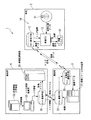
図1に示すように、車載カメラ制御システム1は、車両2、通信局3、および、基地局4を備えて構成される。
車両2は、運転中の車外画像を記録するいわゆるドライブレコーダを具備した不特定多数の車両であり、車載カメラ10と、自車位置測定部(GPS)11と、車載ECU12と、通信手段13とからなる車載機14を備えている。
Next, an in-vehicle camera control system according to an embodiment of the present invention will be described with reference to the drawings.
As shown in FIG. 1, the in-vehicle camera control system 1 includes a
The
車載カメラ10は、車両前方の所定範囲を撮影するカメラであり、例えば車室内のルームミラーの近傍などに取り付けられ、車載ECU12より撮影指令信号が入力されたタイミングで画像を撮像する。車載カメラ10は、撮影した画像を、例えばフィルタリングや、輝度調整や色相調整等の所定の画像処理を行い、二次元配列の画素からなる画像データを生成する。そして、車載カメラ10は、生成された画像データを車載ECU12へ出力する。
The in-
自車位置測定部11は、人工衛星を利用して車両の位置を測定するためのGPS(Global Positioning System)信号や、例えば適宜の基地局を利用してGPS信号の誤差を補正して測位精度を向上させるためのD(Differential)GPS信号等の測位信号を受信するGPS受信部(図示略)と、車両の速度(車速)を検出する車速センサ(図示略)と、水平面内での自車両の向きや鉛直方向に対する傾斜角度(例えば、車両の前後方向軸の鉛直方向に対する傾斜角度や車両重心の上下方向軸周りの回転角であるヨー角等)および傾斜角度の変化量(例えば、ヨーレート等)を検出するジャイロセンサ(図示略)とを備えて構成され、受信した測位信号によって、あるいは、車速やヨーレート等の検出信号に基づく自律航法の算出処理によって、車両の現在位置を算出する。そして、自車位置測定部11は、算出された車両の現在位置を車両位置データとして車載ECU12や、図示しないカーナビゲーション装置へ出力する。
The own vehicle
車載ECU12は、図示しない記憶手段に予め格納されたプログラムを実行する演算装置であって、通信手段13よりトリガ信号が入力されると車載カメラ10に撮影指令信号を出力する。さらに車載ECU12は、撮像された画像データが車載カメラ10より入力されると、この入力された画像データと、自車位置測定部11より入力される車両の位置データおよび撮像時刻データとを関連付けて通信手段13へ出力する。
The in-
通信手段13は、通信局3の対車両通信手段20(後述する)と双方向通信を行うために車載機14に設けられた無線送受信装置であって、主にITS(Intelligent Transport Systems)等で利用されるDSRC(狭域通信;Dedicated Short Range Communications)を用いている。このDSRCを用いた送受信機は、ASKやQPSKなどの変復調回路を有している。
通信手段13は、車載ECU12から車両の位置データおよび撮像時刻データが関連付けられた画像データが入力されると、データに応じた所定の変調を行って無線で通信局3へ出力する一方、通信局3の対車両通信手段20からデータ受信されると復調し、復調されたトリガ信号を車載ECU12へ出力する。ここで、上記DSRCの通信距離が比較的短く設定されているため、通信局3は、各車両1台1台と確実に通信を行うことができる。
The communication means 13 is a wireless transmission / reception device provided in the in-
When the image data in which the vehicle position data and the imaging time data are associated is input from the in-
通信局3は、その設置場所の周辺において車載カメラ10により撮像された画像を収集する路側機であって、例えば道路沿いに設置され、特に十字路やT字路などの交差点近傍に設置される。この通信局3は、対車両通信手段20と、画像ファイル作成装置21と、通信手段22とを備えて構成されている。
The
対車両通信手段20は、上述した車載機14の通信手段13に対してDSRCによる双方向通信を行うものである。図1中、図示都合上、対車両通信手段20を1台のみ示しているが、この対車両通信手段20は、通信局3が例えば十字路近傍に設置されている場合は、少なくとも交差点に合流する4方向の道路にそれぞれ存在している車両2の車載機14と双方向通信を行うべく各4方向の道路に対して指向性を有する4台の対車両通信手段20を備えている。そして、これら4台の対車両通信手段20の通信距離は、交差点に合流する各4本の道路の所定位置に存在する車両2と通信できるように所定の距離に設定されている。同様に、通信局3がT字路近傍に設置されている場合は少なくとも3台の対車両通信手段20を備え、一本道の場合には少なくとも1台の対車両通信手段20を備える。
The vehicle-to-
上記対車両通信手段20は、通信局3の通信手段22よりトリガ情報が入力されると、このトリガ情報を基にトリガ信号を生成して、所定の車載機14へトリガ信号を送信する。また、対車両通信手段20は、車載機14より車両の位置データおよび撮像時刻データが関連付けられた画像データを受信して復調すると、この車両の位置データおよび撮像時刻データが関連付けられた画像データを画像ファイル作成装置21へ出力する。ここで、トリガ情報とは、渋滞情報(交通量)に基づき演算されるものであり、車載カメラ10により撮像を行う時間間隔の情報すなわち、車載機14へ向けてトリガ信号を送信する時間間隔の情報である。
When the trigger information is input from the
画像ファイル作成装置21は、複数の対車両通信手段20に入力された画像データに関連付けられている撮像時刻データに基づいて、同時刻に撮像された画像を単一の画像ファイルにする同一時刻ファイル化処理を行った後、この処理後の画像ファイルの容量を軽減すべくファイル圧縮処理を行う。そして、画像ファイル作成装置21は、圧縮された画像ファイルを通信手段22へ出力する。なお、画像ファイルには、それぞれ撮像時刻や取得した通信局のID情報などが例えばヘッダ等に含まれている。
The image file creation device 21 uses the image time data associated with the image data input to the plurality of vehicle-to-vehicle communication means 20 to convert the images imaged at the same time into a single image file. After performing the conversion processing, file compression processing is performed to reduce the capacity of the image file after the processing. Then, the image file creation device 21 outputs the compressed image file to the
通信手段22は、基地局4の通信手段30と有線又は無線で双方向通信を行うものであり、画像ファイル作成装置21より圧縮された画像ファイルが入力されると、この圧縮された画像ファイルのデータを変調して順次基地局4へ出力する。また、通信手段22は、基地局4より変調されたトリガ情報のデータが入力されると、これを復調し、復調したトリガ情報のデータを対車両通信手段20へ出力する。
The communication means 22 performs two-way communication with the communication means 30 of the
基地局4は、各通信局3に対してトリガ情報を送信することで各通信局3における画像取得の制御処理を行うものであり、通信手段30、画像記録装置31、渋滞情報入手装置32、および、トリガ間隔演算部33を備えて構成される。
通信手段30は、上述した通信局3の通信手段22と有線又は無線により双方向通信を行うもので、通信局3より入力される変調された画像ファイルデータを復調して、その画像ファイルを画像記録装置31へ出力する。
The
The
画像記録装置31は、RAM(Random Access Memory)やHDD(Hard Disk Drive)などの大容量記憶装置を備えて構成され、通信手段30より画像ファイルが入力されると、この画像ファイルを、画像ファイルを送信した通信局3毎に、順次記録する。そして、画像記録装置31に記録されたこれら画像ファイルは、画像ファイルに含まれる撮像時刻や撮影位置(取得した通信局)などの諸条件を情報端末(図示略)により指定することで検索可能となっている。
The image recording apparatus 31 includes a large-capacity storage device such as a RAM (Random Access Memory) or an HDD (Hard Disk Drive). When an image file is input from the
渋滞情報入手装置32は、外部より渋滞や交通事故などの道路交通情報を入手する装置であり、例えば、電波ビーコン、光ビーコン、FM多重放送等を介して道路交通情報を提供するVICS(Vehicle Information and Communication System)を利用し、略リアルタイム(例えば、5分間隔など)で道路交通情報の更新を行う。そして、渋滞情報入手装置32は、トリガ間隔演算部33へ、入手した道路交通情報に基づく渋滞情報を出力する。なお、VICSに限られずインターネット回線などの他の通信回線を介して道路の道路交通情報を取得するようにしても良く、また、例えば過去の渋滞情報に基づく渋滞マップなどを作成して記憶させておき、この渋滞マップを渋滞情報として出力させるようにしてもよい。 The traffic jam information obtaining device 32 is a device that obtains road traffic information such as traffic jams and traffic accidents from the outside. and Communication System) and update road traffic information in near real time (for example, every 5 minutes). Then, the traffic jam information obtaining device 32 outputs the traffic jam information based on the obtained road traffic information to the trigger interval calculation unit 33. Note that road traffic information of roads may be acquired via other communication lines such as the Internet line, not limited to VICS. For example, a traffic jam map based on past traffic jam information may be created and stored. Alternatively, this traffic jam map may be output as traffic jam information.
トリガ間隔演算部33は、渋滞情報入手装置32より入力された渋滞情報に基づいて、通信局3毎にトリガ間隔を演算するものである。このトリガ間隔演算部33で演算されるトリガ間隔は、車載カメラ10で画像を撮像する時間間隔となるものであり、通信局3が設置されている近傍の道路が渋滞などにより交通量が多いほど長くなる。これは、渋滞が発生している道路では、通信可能な位置に車両2が存在する確率が非常に高くなるためであり、撮像間隔が同一で交通量が多いほど同様な画像が多数記録されるからである。
そして、トリガ間隔演算部33による通信局3毎のトリガ間隔の演算結果は、トリガ情報として通信手段30へ出力されて、該当する通信局3へ送信される。
The trigger interval calculation unit 33 calculates a trigger interval for each
Then, the calculation result of the trigger interval for each
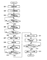
この実施の形態の車載カメラ制御システム1は、上記構成を備えており、次に、この車載カメラ制御システム1の動作について図2のフローチャートを参照しながら説明する。
ステップS01においては、渋滞情報入手装置32により交通量の情報を取得する。
次いで、ステップS02においては、トリガ間隔演算部33によりトリガ間隔を算出する。
さらに、ステップS03においては、基地局4から通信手段30を介して通信局3へトリガ情報を送信する。
The in-vehicle camera control system 1 of this embodiment has the above-described configuration. Next, the operation of the in-vehicle camera control system 1 will be described with reference to the flowchart of FIG.
In step S01, the traffic information is acquired by the traffic jam information obtaining device 32.
Next, in step S02, the trigger interval calculation unit 33 calculates the trigger interval.
Further, in step S03, trigger information is transmitted from the
ステップS04においては、通信局3の通信手段22でトリガ情報が受信されたか否かを判定する。ステップS04における判定結果が「No」(受信無し)である場合は、受信を待つべく再度ステップS04の判定処理を繰り返す。
一方、ステップS04における判定の結果「Yes」(受信あり)である場合は、ステップS05に進み、通信局3の通信手段22で受信したトリガ情報に基づき対車両通信手段20によりトリガ信号を生成して車両2の車載機14へ送信する。
In step S04, it is determined whether or not the trigger information is received by the communication means 22 of the
On the other hand, if the result of determination in step S04 is “Yes” (reception occurs), the process proceeds to step S05, and the trigger signal is generated by the vehicle communication means 20 based on the trigger information received by the communication means 22 of the
ステップS06においては、車載機14の通信手段13でトリガ信号が受信されたか否かを判定する。ステップS06における判定結果が「No」(受信無し)である場合は、受信を待つべく再度ステップS06の判定処理を繰り返す。
一方、ステップS06における判定結果が「Yes」(受信あり)である場合は、ステップS07へ進み、車載ECU12から車載カメラ10へ撮影指令を出力し、車両2の外部画像の撮像を行う。
In step S06, it is determined whether the trigger signal is received by the communication means 13 of the in-
On the other hand, if the determination result in step S06 is “Yes” (reception is present), the process proceeds to step S07, where a shooting command is output from the in-
ステップS08においては、車載ECU12により撮像された画像の処理として、自車位置測定部11より入力される車両位置データに基づいて、位置データおよび撮像時刻データとを画像に関連付けて画像データとする。
ステップS09においては、車両2の車載機14から通信手段13を介して画像データを通信局3へ送信する。
ステップS10においては、通信局3にて画像データが受信されたか否かを判定する。
ステップS10における判定結果が「No」(受信なし)である場合は、受信を待つべく再度ステップS10の判定処理を繰り返す。
一方、ステップS10における判定結果が「Yes」(受信あり)である場合は、ステップS11へ進み、受信した画像データを画像ファイル作成装置21によりファイル化し、ステップS12において、ファイル化した画像ファイルを圧縮して通信手段22を介して基地局4へ送信する。
In step S08, as processing of an image captured by the in-
In step S <b> 09, the image data is transmitted from the in-
In step S10, it is determined whether or not image data is received by the
If the determination result in step S10 is “No” (no reception), the determination process in step S10 is repeated again to wait for reception.
On the other hand, if the determination result in step S10 is “Yes” (reception occurs), the process proceeds to step S11, where the received image data is filed by the image file creation device 21, and the filed image file is compressed in step S12. Then, the data is transmitted to the
ステップS13においては、基地局4にて画像ファイルが受信されたか否かを判定する。ステップS13における判定結果が「No」(受信なし)である場合は、受信を待つべく再度ステップS13の判定処理を繰り返す。
一方、ステップS13における判定結果が「Yes」(受信あり)である場合は、ステップS14へ進み、画像ファイルを画像記録装置31へ記録してこの一連の処理を一旦終了してリターンする。
In step S13, it is determined whether the
On the other hand, if the determination result in step S13 is “Yes” (reception is present), the process proceeds to step S14, the image file is recorded in the image recording device 31, this series of processes is once terminated, and the process returns.
すなわち、基地局4のトリガ間隔演算部33により交通量に応じて演算したトリガ信号を送信する間隔をトリガ情報として通信局3へ送信すると、トリガ情報を受信した通信局3の対車両通信手段20よりトリガ信号が車両2へ向けて送信し、トリガ信号を受信した車載機14では、トリガ信号の受信タイミングに応じて車載カメラ10により車両周辺の画像を撮像し、車両2の位置情報や撮像された時刻情報を関連付ける処理を行った後、この画像データを通信局3へ送信する。さらに、画像データを受信した通信局3においては、同一時刻に撮像された画像データをファイル化し、このファイル化した画像ファイルを基地局4へ送信して、画像ファイルを受信した基地局4においては、受信した画像ファイルを画像記録装置31に記録する。
In other words, when the interval for transmitting the trigger signal calculated according to the traffic volume by the trigger interval calculation unit 33 of the
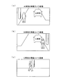
ここで、図3は、T字交差点に設置された通信局3における画像取得の一例を示したものであり、このT字交差点においては、交差する道路にそれぞれ存在するA車両、B車両、および、C車両に向けて通信局3よりトリガ信号が送信され、A車両、B車両、および、C車両において、トリガ信号が入力されたタイミングで車載カメラ10による撮像が行われる。図4(a)〜(c)は、A車両、B車両、および、C車両で撮像された画像の一例を示しており、それぞれ異なった角度から撮像された画像となる。図3,4に示す一例のようにT字交差点に不審者が存在していた場合、それぞれ異なった角度から複数の撮像が行われているので、A車両およびC車両で撮像された画像において不審者の顔が捉えられていないが、別角度のB車両により撮像された画像により不審者の顔が捉えられている。
Here, FIG. 3 shows an example of image acquisition at the
したがって、上述した実施の形態における車載カメラ制御システム1によれば、通信局3が設置された近傍の道路の交通量に応じたトリガ間隔すなわち、通信局3が設置された近傍の道路を通行する車両2の数量に応じたタイミングで画像が撮像されるため、画像が記録され過ぎたり、撮像漏れが生じたりするのを防止して画像記録装置31に記録される画像ファイルの数を適正化することができる。
Therefore, according to the vehicle-mounted camera control system 1 in the above-described embodiment, the trigger interval according to the traffic volume of the nearby road where the
また、交通量が多いほどトリガ間隔演算部33により演算されるトリガ間隔が長くなることで、渋滞により通信局3が設置された道路を車両2が頻繁に通過する場合にトリガ信号の送信間隔が長くなり、画像が通信局3へ頻繁に送信されてくるのを防止することができるため、必要以上の画像が画像記録手段に無駄に記録されるのを防止することができる。
Further, the trigger interval calculated by the trigger interval calculation unit 33 becomes longer as the traffic volume increases, so that the transmission interval of the trigger signal is increased when the
さらに、車載機14の自車位置測定部11により測位された現在位置を、撮像した位置情報として車載ECU12により画像に関連付けて送信することができるため、基地局4の画像記録装置31に記録されている画像が撮像された位置すなわち、どの通信局3が設置された道路の画像であるかを容易に特定することができる。
Furthermore, since the current position measured by the vehicle
そして、DSRC(狭域無線)を用いることにより、対車両通信手段20が通信を行っている相手の通信手段13を特定することができるため、他の車両2の通信手段13が行う送受信の影響を排除することができる。
Then, by using DSRC (narrow band radio), the communication means 13 of the other party with which the vehicle-to-vehicle communication means 20 is communicating can be specified, and therefore the influence of transmission / reception performed by the communication means 13 of the
また、交差点においては、道路の交差する数に応じてそれぞれ異なった角度から撮像した画像を車両2の車載カメラ10より取得することができるため、従来の防犯カメラを用いて撮像する場合と比較してカメラ台数増加によるコストアップを抑制しつつ有用な画像を容易に取得することができる。
In addition, at the intersection, images taken from different angles depending on the number of road intersections can be obtained from the in-
なお、上述した実施の形態では、車両2が前方を撮像する車載カメラ10のみを具備している場合について説明したが、これに限られず、例えば、車両2の前方に加えて、後方や側方などを撮像する車載カメラ10を設けるようにしてもよい。
また、上述した実施の形態では、画像データに対して撮像時刻データを関連付ける処理を車両2で行う場合について説明したが、これに限られず、例えば、通信局3で撮像時刻データを関連付けするようにしてもよい。
In the above-described embodiment, the case where the
Further, in the above-described embodiment, the case where the process of associating the imaging time data with the image data is performed in the
2 車両
3 通信局(路側機)
4 基地局
10 車載カメラ
12 車載ECU(車載画像処理手段)
13 通信手段(車載通信手段)
14 車載機
20 対車両通信手段(第1路側機通信手段)
22 通信手段(第2路側機通信手段)
30 通信手段(基地局通信手段)
31 画像記録装置(画像記録手段)
33 トリガ間隔演算部(トリガ間隔演算手段)
2
4
13 Communication means (vehicle communication means)
14 vehicle-mounted
22 Communication means (second roadside machine communication means)
30 communication means (base station communication means)
31 Image recording device (image recording means)
33 Trigger interval calculation unit (trigger interval calculation means)
Claims (5)
前記画像を車両外部へ送信するための処理を行う車載画像処理手段と、
前記トリガ信号を車両外部より受信する一方、前記車載画像処理手段により処理した画像を車両外部へ送信する車載通信手段とをそれぞれ備え車両に搭載された車載機と、
前記車載通信手段に対して前記トリガ信号を送信する一方、前記車載通信手段より画像を受信する第1路側機通信手段と、
該第1路側機通信手段から前記車載通信手段へ前記トリガ信号を送信する間隔情報を基地局から受信する一方、前記第1路側機通信手段によって受信した前記画像を基地局へ送信する第2路側機通信手段とをそれぞれ備え道路に設置された路側機と、
前記トリガ信号を送信する間隔を演算するトリガ間隔演算手段と、
該トリガ間隔演算手段による演算結果を間隔情報として前記路側機へ送信する一方、前記路側機から前記画像を受信する基地局通信手段と、
該基地局通信手段によって受信された前記画像を記録する画像記録手段とをそれぞれ備える基地局とからなり、
前記トリガ間隔演算手段は、前記路側機が設置された道路の交通量に応じて前記トリガ信号を送信する間隔を演算することを特徴とする車載カメラ制御システム。 An in-vehicle camera that captures an image around the vehicle based on a trigger signal received from outside the vehicle;
Vehicle-mounted image processing means for performing processing for transmitting the image to the outside of the vehicle;
An in-vehicle device mounted on the vehicle, each of which includes an in-vehicle communication unit that receives the trigger signal from the outside of the vehicle and transmits an image processed by the in-vehicle image processing unit to the outside of the vehicle;
A first roadside machine communication means for transmitting the trigger signal to the in-vehicle communication means, and receiving an image from the in-vehicle communication means;
A second roadside for receiving interval information for transmitting the trigger signal from the first roadside machine communication means to the in-vehicle communication means from the base station, while transmitting the image received by the first roadside machine communication means to the base station. A roadside machine installed on the road, each having a machine communication means,
Trigger interval calculation means for calculating an interval for transmitting the trigger signal;
Base station communication means for transmitting the calculation result by the trigger interval calculation means to the roadside machine as interval information, and receiving the image from the roadside machine;
Each comprising a base station comprising image recording means for recording the image received by the base station communication means,
The in-vehicle camera control system, wherein the trigger interval calculation means calculates an interval for transmitting the trigger signal in accordance with a traffic volume on a road where the roadside unit is installed.
前記車両画像処理手段は、前記画像と前記現在位置とを関連付けて送信することを特徴とする請求項1又は2に記載の車載カメラ制御システム。 The in-vehicle device includes positioning means for measuring the current position of the vehicle,
The in-vehicle camera control system according to claim 1, wherein the vehicle image processing unit transmits the image in association with the current position.
Priority Applications (1)
| Application Number | Priority Date | Filing Date | Title |
|---|---|---|---|
| JP2008325125A JP2010146443A (en) | 2008-12-22 | 2008-12-22 | On-vehicle camera control system |
Applications Claiming Priority (1)
| Application Number | Priority Date | Filing Date | Title |
|---|---|---|---|
| JP2008325125A JP2010146443A (en) | 2008-12-22 | 2008-12-22 | On-vehicle camera control system |
Publications (1)
| Publication Number | Publication Date |
|---|---|
| JP2010146443A true JP2010146443A (en) | 2010-07-01 |
Family
ID=42566793
Family Applications (1)
| Application Number | Title | Priority Date | Filing Date |
|---|---|---|---|
| JP2008325125A Pending JP2010146443A (en) | 2008-12-22 | 2008-12-22 | On-vehicle camera control system |
Country Status (1)
| Country | Link |
|---|---|
| JP (1) | JP2010146443A (en) |
Cited By (6)
| Publication number | Priority date | Publication date | Assignee | Title |
|---|---|---|---|---|
| WO2013077331A1 (en) * | 2011-11-25 | 2013-05-30 | 日産自動車株式会社 | Monitoring system |
| WO2013094405A1 (en) * | 2011-12-21 | 2013-06-27 | 日産自動車株式会社 | Monitoring system |
| WO2013111494A1 (en) * | 2012-01-23 | 2013-08-01 | 日産自動車株式会社 | Monitoring system |
| WO2013136894A1 (en) * | 2012-03-12 | 2013-09-19 | 日産自動車株式会社 | Monitoring system and monitoring method |
| JP2023063433A (en) * | 2018-05-14 | 2023-05-09 | 株式会社デンソーテン | Terminal device, transmission method, collection device and collection system |
| CN116176660A (en) * | 2023-02-22 | 2023-05-30 | 北京全路通信信号研究设计院集团有限公司 | Method for checking driving permit in ATO mode, vehicle-mounted equipment and system |
-
2008
- 2008-12-22 JP JP2008325125A patent/JP2010146443A/en active Pending
Cited By (7)
| Publication number | Priority date | Publication date | Assignee | Title |
|---|---|---|---|---|
| WO2013077331A1 (en) * | 2011-11-25 | 2013-05-30 | 日産自動車株式会社 | Monitoring system |
| JPWO2013077331A1 (en) * | 2011-11-25 | 2015-04-27 | 日産自動車株式会社 | Monitoring system |
| WO2013094405A1 (en) * | 2011-12-21 | 2013-06-27 | 日産自動車株式会社 | Monitoring system |
| WO2013111494A1 (en) * | 2012-01-23 | 2013-08-01 | 日産自動車株式会社 | Monitoring system |
| WO2013136894A1 (en) * | 2012-03-12 | 2013-09-19 | 日産自動車株式会社 | Monitoring system and monitoring method |
| JP2023063433A (en) * | 2018-05-14 | 2023-05-09 | 株式会社デンソーテン | Terminal device, transmission method, collection device and collection system |
| CN116176660A (en) * | 2023-02-22 | 2023-05-30 | 北京全路通信信号研究设计院集团有限公司 | Method for checking driving permit in ATO mode, vehicle-mounted equipment and system |
Similar Documents
| Publication | Publication Date | Title |
|---|---|---|
| TWI904178B (en) | Techniques for managing data distribution in a v2x environment | |
| JP6104482B1 (en) | Accident information collection system and accident information collection method | |
| JP6801619B2 (en) | Data transfer route calculation device and data transfer terminal | |
| KR20170081920A (en) | Method and apparatus for sharing video information associated with a vihicle | |
| JP5018613B2 (en) | Road communicator and accident monitoring system | |
| CN111762197A (en) | Vehicle operation in response to an emergency event | |
| US20190115049A1 (en) | Recording device and recording method | |
| JP2007288444A (en) | In-vehicle camera control device and in-vehicle camera control method. | |
| JP2006279859A (en) | Mobile body movement actual information provision system, position information collection device, car navigation device, and mobile body movement actual information provision method | |
| JP2008102762A (en) | Image collection system and recording device | |
| JP2017117005A (en) | Accident notification system, notification system, on-vehicle notification device and accident notification method | |
| JP2010146443A (en) | On-vehicle camera control system | |
| KR101612836B1 (en) | Method and device for acquisiting accident image in vehicle, and computer readable medium for performing the method | |
| JP2010055157A (en) | Intersection situation recognition system | |
| US11776408B2 (en) | Methods and apparatuses for dynamic cloud-based vehicle dispatch | |
| JP2012198599A (en) | Recording device | |
| JP7348724B2 (en) | In-vehicle device and display method | |
| JP2011204151A (en) | Inter-vehicle communication method and inter-vehicle communication device | |
| US11594038B2 (en) | Information processing device, information processing system, and recording medium recording information processing program | |
| CN109624991B (en) | Geogramming and time stamp data protected by digital signatures shared over private networks | |
| US7432804B2 (en) | Emergency notification apparatus for vehicle | |
| JP2025072650A (en) | Information processing device | |
| WO2018109865A1 (en) | Roadside machine and vehicle-to-road communication system | |
| JP2018198004A (en) | Communication apparatus, communication system, and communication method | |
| JP2006293558A (en) | Accident information acquisition system |