JP2010210285A - 混合流体の濃度検出方法および検出装置 - Google Patents
混合流体の濃度検出方法および検出装置 Download PDFInfo
- Publication number
- JP2010210285A JP2010210285A JP2009054056A JP2009054056A JP2010210285A JP 2010210285 A JP2010210285 A JP 2010210285A JP 2009054056 A JP2009054056 A JP 2009054056A JP 2009054056 A JP2009054056 A JP 2009054056A JP 2010210285 A JP2010210285 A JP 2010210285A
- Authority
- JP
- Japan
- Prior art keywords
- mixed fluid
- temperature
- concentration
- component
- dielectric constant
- Prior art date
- Legal status (The legal status is an assumption and is not a legal conclusion. Google has not performed a legal analysis and makes no representation as to the accuracy of the status listed.)
- Granted
Links
Images


Landscapes
- Investigating Or Analyzing Materials By The Use Of Electric Means (AREA)
Abstract
【解決手段】N(≧3の整数)種の既知の成分で構成される混合流体の各成分の濃度を検出する混合流体の濃度検出方法であって、(N−1)点の異なる温度で前記混合流体の誘電率を測定し、前記(N−1)点の各温度における既知の各成分の誘電率と、前記(N−1)点の各温度で測定された前記混合流体の誘電率とから、前記各成分の濃度を算出する。
【選択図】図2
Description
(数1) a+b+c=1
(数2) ε1=εa1・a+εb1・b+εc1・c
(数3) ε2=εa2・a+εb2・b+εc2・c
から、前記各成分の濃度を算出することができる。
(数1) a+b+c=1
(数2) ε1=εa1・a+εb1・b+εc1・c
(数3) ε2=εa2・a+εb2・b+εc2・c
から、前記各成分の濃度を算出する。
(数1) a+b+c=1
(数2) ε1=εa1・a+εb1・b+εc1・c
(数3) ε2=εa2・a+εb2・b+εc2・c
が成立する。該数式1〜3の連立方程式を解くことにより、各成分A,B,Cの濃度a,b,cを算出することができる。
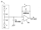
(数4) Vs=V(Cs1−Cs2)/Cf
となり、2個の容量検出素子Cs1,Cs2の差分が、C/V変換される。この数式4の出力電圧Vsから、混合流体の各温度における誘電率を測定することができる。図5の誘電率測定部24を用いた誘電率測定によれば、配線による寄生容量Ceの影響をキャンセルできるため、1個の容量検出素子を用いる場合に較べてより高精度な誘電率測定が可能であり、各成分の濃度もより高精度に検出することができる。
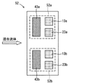
10 温度測定部
11,12a,12b,13a,13b 温度検出素子
20,24 誘電率測定部
21,21a,22a,22b,23a,23b 容量検出素子
30 濃度演算部
40 ヒータ部
41,42,43a,43b ヒータ素子
50〜52 センサチップ
61,62 センサ部品
70 配管
80 攪拌手段
Claims (17)
- N(≧3の整数)種の既知の成分で構成される混合流体の各成分の濃度を検出する混合流体の濃度検出方法であって、
(N−1)点の異なる温度で前記混合流体の誘電率を測定し、
前記(N−1)点の各温度における既知の各成分の誘電率と、前記(N−1)点の各温度で測定された前記混合流体の誘電率とから、前記各成分の濃度を算出することを特徴とする混合流体の濃度検出方法。 - 前記Nが、3であり、
前記各成分の濃度をそれぞれa,b,cとし、前記2点の異なる温度をそれぞれT1,T2とし、前記温度T1における各成分の誘電率をそれぞれεa1,εb1,εc1とし、前記温度T2における各成分の誘電率をそれぞれεa2,εb2,εc2とし、前記温度T1と温度T2における混合流体の誘電率をそれぞれε1,ε2としたとき、
(数1) a+b+c=1
(数2) ε1=εa1・a+εb1・b+εc1・c
(数3) ε2=εa2・a+εb2・b+εc2・c
から、前記各成分の濃度を算出することを特徴とする請求項1に記載の混合流体の濃度検出方法。 - 前記成分が、エタノール、ガソリンおよび水であることを特徴とする請求項2に記載の混合流体の濃度検出方法。
- 前記成分が、脂肪酸メチルエステル、軽油および水であることを特徴とする請求項2に記載の混合流体の濃度検出方法。
- 前記混合流体の各温度における誘電率の測定において、
直列接続された2個の容量検出素子を所定電圧の逆の搬送波で駆動し、前記2個の容量検出素子の接続点からの出力を帰還容量が付加されたC/V変換器に入力し、該C/V変換器の出力電圧から前記混合流体の各温度における誘電率を測定することを特徴とする請求項1乃至4のいずれか一項に記載の混合流体の濃度検出方法。 - N(≧3の整数)種の既知の成分で構成される混合流体の各成分の濃度を検出する混合流体の濃度検出装置であって、
前記混合流体の温度を異なる(N−1)点で測定可能な温度測定部と、
前記(N−1)点の異なる温度で前記混合流体の誘電率を測定可能な誘電率測定部と、
メモリに保存された前記(N−1)点の各温度における既知の各成分の誘電率と、前記(N−1)点の異なる温度で測定された前記混合流体の誘電率とから、前記各成分の濃度を算出する濃度演算部とを有してなることを特徴とする混合流体の濃度検出装置。 - 前記濃度検出装置が、
前記混合流体の前記(N−1)点の異なる温度を形成するためのヒータ部を有してなることを特徴とする請求項6に記載の混合流体の濃度検出装置。 - 前記温度測定部の構成要素である温度検出素子および前記誘電率測定部の構成要素である容量検出素子が、一つのチップに形成されてなることを特徴とする請求項6または7に記載の混合流体の濃度検出装置。
- 前記温度測定部の構成要素である温度検出素子、前記誘電率測定部の構成要素である容量検出素子および前記ヒータ部の構成要素であるヒータ素子が、一つのチップに形成されてなることを特徴とする請求項7に記載の混合流体の濃度検出装置。
- 前記チップにおいて、
前記ヒータ素子と前記温度検出素子および前記容量検出素子を熱的に分離するように、溝部が形成されてなることを特徴とする請求項9に記載の混合流体の濃度検出装置。 - 前記容量検出素子が、一対の櫛歯状電極からなることを特徴とする請求項8乃至10のいずれか一項に記載の混合流体の濃度検出装置。
- 前記混合流体の上流側に配置された前記ヒータ部の構成要素であるヒータ素子と、前記混合流体の下流側に配置された前記温度測定部の構成要素である温度検出素子および前記誘電率測定部の構成要素である容量検出素子との間に、
前記混合流体の攪拌手段が設けられてなることを特徴とする請求項7に記載の混合流体の濃度検出装置。 - 前記誘電率測定部の構成要素である容量検出素子が、一対の電極からなり、
該電極の一方が、前記温度測定部の構成要素である温度検出素子を兼ねることを特徴とする請求項6乃至12のいずれか一項に記載の混合流体の濃度検出装置。 - 前記誘電率測定部が、
直列接続された2個の容量検出素子と帰還容量が付加されたC/V変換器とを有してなり、
前記混合流体の各温度における誘電率の測定において、
前記2個の容量検出素子を所定電圧の逆の搬送波で駆動し、前記2個の容量検出素子の接続点からの出力を前記C/V変換器に入力し、該C/V変換器の出力電圧から前記混合流体の各温度における誘電率を測定することを特徴とする請求項6乃至13のいずれか一項に記載の混合流体の濃度検出装置。 - 前記Nが、3であり、
前記濃度演算部が、
前記各成分の濃度をそれぞれa,b,cとし、前記2点の異なる温度をそれぞれT1,T2とし、前記温度T1における各成分の誘電率をそれぞれεa1,εb1,εc1とし、前記温度T2における各成分の誘電率をそれぞれεa2,εb2,εc2とし、前記温度T1と温度T2における混合流体の誘電率をそれぞれε1,ε2としたとき、
(数1) a+b+c=1
(数2) ε1=εa1・a+εb1・b+εc1・c
(数3) ε2=εa2・a+εb2・b+εc2・c
から、前記各成分の濃度を算出することを特徴とする請求項6乃至14のいずれか一項に記載の混合流体の濃度検出装置。 - 前記成分が、エタノール、ガソリンおよび水であることを特徴とする請求項15に記載の混合流体の濃度検出装置。
- 前記成分が、脂肪酸メチルエステル、軽油および水であることを特徴とする請求項15に記載の混合流体の濃度検出装置。
Priority Applications (4)
| Application Number | Priority Date | Filing Date | Title |
|---|---|---|---|
| JP2009054056A JP5056776B2 (ja) | 2009-03-06 | 2009-03-06 | 混合流体の濃度検出方法および検出装置 |
| PCT/JP2009/001334 WO2009119087A1 (ja) | 2008-03-26 | 2009-03-25 | 濃度センサ装置、及び濃度検出方法 |
| BRPI0907020-6A BRPI0907020A2 (pt) | 2008-03-26 | 2009-03-25 | Dispositivo sensor de concentração, dispositivo de cálculo da relação de mistura, métodos para calcular uma ralação de mistura do líquido de mistura e para detectar concentrações do fluido e, dispositivo de detecção de concentração |
| US12/733,694 US8578761B2 (en) | 2008-03-26 | 2009-03-25 | Concentration sensor device and concentration detecting method |
Applications Claiming Priority (1)
| Application Number | Priority Date | Filing Date | Title |
|---|---|---|---|
| JP2009054056A JP5056776B2 (ja) | 2009-03-06 | 2009-03-06 | 混合流体の濃度検出方法および検出装置 |
Publications (2)
| Publication Number | Publication Date |
|---|---|
| JP2010210285A true JP2010210285A (ja) | 2010-09-24 |
| JP5056776B2 JP5056776B2 (ja) | 2012-10-24 |
Family
ID=42970626
Family Applications (1)
| Application Number | Title | Priority Date | Filing Date |
|---|---|---|---|
| JP2009054056A Expired - Fee Related JP5056776B2 (ja) | 2008-03-26 | 2009-03-06 | 混合流体の濃度検出方法および検出装置 |
Country Status (1)
| Country | Link |
|---|---|
| JP (1) | JP5056776B2 (ja) |
Cited By (4)
| Publication number | Priority date | Publication date | Assignee | Title |
|---|---|---|---|---|
| JP2015500470A (ja) * | 2011-11-30 | 2015-01-05 | ゼネラル・エレクトリック・カンパニイ | 多相流体の高位の電流測定技法 |
| JP2015169179A (ja) * | 2014-03-10 | 2015-09-28 | 愛三工業株式会社 | センサ装置 |
| WO2017086214A1 (ja) * | 2015-11-16 | 2017-05-26 | ナブテスコ株式会社 | センサ装置 |
| JP2017535766A (ja) * | 2014-10-07 | 2017-11-30 | ベルキン ビーブイBerkin B.V. | 流動ガス状媒質の割合の決定方法およびそれと共に使用するためのシステム |
Citations (6)
| Publication number | Priority date | Publication date | Assignee | Title |
|---|---|---|---|---|
| JPS56148047A (en) * | 1980-04-18 | 1981-11-17 | Koumiyou Rikagaku Kogyo Kk | Thermal conductivity type gas detector |
| JPS59131154A (ja) * | 1983-01-14 | 1984-07-27 | Komatsu Ltd | 誘電率測定センサ |
| JPH08201326A (ja) * | 1995-01-30 | 1996-08-09 | Gastar Corp | 燃焼機器の排気co濃度検出装置 |
| JP2571465B2 (ja) * | 1990-10-17 | 1997-01-16 | 株式会社ユニシアジェックス | ガソリン性状判別装置 |
| JP2004125465A (ja) * | 2002-09-30 | 2004-04-22 | Mitsui Mining & Smelting Co Ltd | ガソリンの液種識別装置およびガソリンの液種識別方法 |
| JP2005201670A (ja) * | 2004-01-13 | 2005-07-28 | Mitsui Mining & Smelting Co Ltd | アルコール濃度センサ及びアルコール濃度測定装置 |
-
2009
- 2009-03-06 JP JP2009054056A patent/JP5056776B2/ja not_active Expired - Fee Related
Patent Citations (6)
| Publication number | Priority date | Publication date | Assignee | Title |
|---|---|---|---|---|
| JPS56148047A (en) * | 1980-04-18 | 1981-11-17 | Koumiyou Rikagaku Kogyo Kk | Thermal conductivity type gas detector |
| JPS59131154A (ja) * | 1983-01-14 | 1984-07-27 | Komatsu Ltd | 誘電率測定センサ |
| JP2571465B2 (ja) * | 1990-10-17 | 1997-01-16 | 株式会社ユニシアジェックス | ガソリン性状判別装置 |
| JPH08201326A (ja) * | 1995-01-30 | 1996-08-09 | Gastar Corp | 燃焼機器の排気co濃度検出装置 |
| JP2004125465A (ja) * | 2002-09-30 | 2004-04-22 | Mitsui Mining & Smelting Co Ltd | ガソリンの液種識別装置およびガソリンの液種識別方法 |
| JP2005201670A (ja) * | 2004-01-13 | 2005-07-28 | Mitsui Mining & Smelting Co Ltd | アルコール濃度センサ及びアルコール濃度測定装置 |
Cited By (5)
| Publication number | Priority date | Publication date | Assignee | Title |
|---|---|---|---|---|
| JP2015500470A (ja) * | 2011-11-30 | 2015-01-05 | ゼネラル・エレクトリック・カンパニイ | 多相流体の高位の電流測定技法 |
| JP2015169179A (ja) * | 2014-03-10 | 2015-09-28 | 愛三工業株式会社 | センサ装置 |
| JP2017535766A (ja) * | 2014-10-07 | 2017-11-30 | ベルキン ビーブイBerkin B.V. | 流動ガス状媒質の割合の決定方法およびそれと共に使用するためのシステム |
| WO2017086214A1 (ja) * | 2015-11-16 | 2017-05-26 | ナブテスコ株式会社 | センサ装置 |
| JPWO2017086214A1 (ja) * | 2015-11-16 | 2018-08-23 | ナブテスコ株式会社 | センサ装置 |
Also Published As
| Publication number | Publication date |
|---|---|
| JP5056776B2 (ja) | 2012-10-24 |
Similar Documents
| Publication | Publication Date | Title |
|---|---|---|
| US8578761B2 (en) | Concentration sensor device and concentration detecting method | |
| US9027387B2 (en) | Multifunctional potentiometric gas sensor array with an integrated temperature control and temperature sensors | |
| Baier et al. | Highly sensitive thermopile heat power sensor for micro-fluid calorimetry of biochemical processes | |
| US7692432B2 (en) | Liquid property sensor | |
| JP5056776B2 (ja) | 混合流体の濃度検出方法および検出装置 | |
| CN101308036A (zh) | 热式流量计 | |
| Goel et al. | Rapid and automated measurement of biofuel blending using a microfluidic viscometer | |
| Gauthier et al. | Gas thermal conductivity measurement using the three-omega method | |
| Bruschi et al. | A single chip, double channel thermal flow meter | |
| Hepp et al. | Flow rate independent sensing of thermal conductivity in a gas stream by a thermal MEMS-sensor–Simulation and experiments | |
| Agostini et al. | Effects of geometrical and thermophysical parameters on heat transfer measurements in small-diameter channels | |
| Lötters et al. | Fully integrated microfluidic measurement system for real-time determination of gas and liquid mixtures composition | |
| US20110209526A1 (en) | Method and thermal, flow measuring device for determining and/or monitoring at least one variable dependent on at least the chemical composition of a measured medium | |
| CN101408442A (zh) | 硅基薄膜结构空气质量流量传感器 | |
| Kazemi et al. | Accurate and rapid measurement of fluid thermal conductivity | |
| CN1252466C (zh) | 一种测定导热系数的方法及装置 | |
| CN114100708B (zh) | 微流体浓度传感芯片及微流体特性测量装置 | |
| Ghaderi et al. | MEMS for biofuel composition measurement based on thermal impedance spectroscopy | |
| CN102636524A (zh) | 电法瞬态测量材料热物性的装置及方法 | |
| CN104101643A (zh) | 用于分析气体的方法 | |
| Azadi Kenari et al. | Gas-compensated thermal flow sensor using an integrated velocity-independent gas properties meter | |
| Kuvshinov et al. | Thermal conductivity measurement of liquids in a microfluidic device | |
| Piotto et al. | Low pressure drop, CMOS compatible liquid flow sensor with sub ml/h resolution | |
| Venkateswaran et al. | Computational analysis of a microfluidic viscometer and its application in the rapid and automated measurement of biodiesel blending under pressure driven flow | |
| US12596085B2 (en) | Method and apparatus for simultaneously measuring air contained hydrogen and water vapor concentrations via a single MEMS thermal conductivity sensor |
Legal Events
| Date | Code | Title | Description |
|---|---|---|---|
| A131 | Notification of reasons for refusal |
Free format text: JAPANESE INTERMEDIATE CODE: A131 Effective date: 20120417 |
|
| A521 | Written amendment |
Free format text: JAPANESE INTERMEDIATE CODE: A523 Effective date: 20120611 |
|
| TRDD | Decision of grant or rejection written | ||
| A01 | Written decision to grant a patent or to grant a registration (utility model) |
Free format text: JAPANESE INTERMEDIATE CODE: A01 Effective date: 20120703 |
|
| A01 | Written decision to grant a patent or to grant a registration (utility model) |
Free format text: JAPANESE INTERMEDIATE CODE: A01 |
|
| A61 | First payment of annual fees (during grant procedure) |
Free format text: JAPANESE INTERMEDIATE CODE: A61 Effective date: 20120716 |
|
| FPAY | Renewal fee payment (event date is renewal date of database) |
Free format text: PAYMENT UNTIL: 20150810 Year of fee payment: 3 |
|
| FPAY | Renewal fee payment (event date is renewal date of database) |
Free format text: PAYMENT UNTIL: 20150810 Year of fee payment: 3 |
|
| R250 | Receipt of annual fees |
Free format text: JAPANESE INTERMEDIATE CODE: R250 |
|
| R250 | Receipt of annual fees |
Free format text: JAPANESE INTERMEDIATE CODE: R250 |
|
| R250 | Receipt of annual fees |
Free format text: JAPANESE INTERMEDIATE CODE: R250 |
|
| LAPS | Cancellation because of no payment of annual fees |