JP2010242514A - Internal combustion engine control system - Google Patents
Internal combustion engine control system Download PDFInfo
- Publication number
- JP2010242514A JP2010242514A JP2009089255A JP2009089255A JP2010242514A JP 2010242514 A JP2010242514 A JP 2010242514A JP 2009089255 A JP2009089255 A JP 2009089255A JP 2009089255 A JP2009089255 A JP 2009089255A JP 2010242514 A JP2010242514 A JP 2010242514A
- Authority
- JP
- Japan
- Prior art keywords
- engine
- internal combustion
- passage
- exhaust
- throttle valve
- Prior art date
- Legal status (The legal status is an assumption and is not a legal conclusion. Google has not performed a legal analysis and makes no representation as to the accuracy of the status listed.)
- Granted
Links
Images




Landscapes
- Control Of Throttle Valves Provided In The Intake System Or In The Exhaust System (AREA)
- Output Control And Ontrol Of Special Type Engine (AREA)
- Electrical Control Of Air Or Fuel Supplied To Internal-Combustion Engine (AREA)
Abstract
【課題】EGR装置を備えた内燃機関においてEGR通路をガスが逆流することを抑制する技術を提供する。
【解決手段】内燃機関の排気通路と吸気通路とを連通するEGR通路と、前記EGR通路の接続部より上流側の吸気通路に設けられたスロットル弁と、前記EGR通路を介して排気の再循環が行われ且つ機関負荷が所定負荷以下である運転条件下において、前記スロットル弁の開度を所定開度以上の開度まで開弁する要求を伴う制御要求があった場合に、当該制御要求における目標の機関負荷よりも軽負荷且つ目標の機関回転数よりも高回転数の運転状態となるように前記内燃機関の制御を行う制御手段と、を備える。
【選択図】図4A technique for suppressing the backflow of gas through an EGR passage in an internal combustion engine equipped with an EGR device is provided.
An EGR passage communicating an exhaust passage and an intake passage of an internal combustion engine, a throttle valve provided in an intake passage upstream of a connection portion of the EGR passage, and recirculation of exhaust gas through the EGR passage And there is a control request accompanied by a request to open the throttle valve to an opening greater than or equal to a predetermined opening under operating conditions where the engine load is equal to or less than the predetermined load, Control means for controlling the internal combustion engine so as to be in an operating state with a lighter load than the target engine load and a higher engine speed than the target engine speed.
[Selection] Figure 4
Description
本発明は、内燃機関の制御システムに関する。 The present invention relates to a control system for an internal combustion engine.
内燃機関の排気通路と吸気通路とを連通するEGR通路を介して内燃機関から排出された排気の一部を吸気通路に流入させるEGR装置を備えた内燃機関が知られている。 2. Description of the Related Art There is known an internal combustion engine that includes an EGR device that causes part of exhaust gas discharged from an internal combustion engine to flow into an intake passage via an EGR passage that connects the exhaust passage and the intake passage of the internal combustion engine.
特許文献1には、EGR装置と過給機とを備えた内燃機関において、EGRガスの流量が所定の閾値より小さい場合にEGR弁を閉弁する技術が記載されている。
特許文献2には、EGR通路の途中に逆止弁を設け、EGRガスの逆流を防止する技術が記載されている。
特許文献3には、吸気通路と排気通路とを接続する通路を設け、吸気圧力や排気圧力の周期的な変動に同期して該通路に設けたバルブの開度を変動させる技術が記載されている。
排気圧力の低い軽負荷運転状態からの加速時等において、スロットル弁が全開(WOT)又はそれに近い開度まで急激に開弁されると、吸気圧力が急激に上昇して一時的に排気圧力より高くなる場合がある。EGR装置を備えた内燃機関においてEGR通路を介した排気の再循環が行われている時にこのように吸気圧力が排気圧力より高くなった場合、EGR通路を吸気通路側から排気通路側へガスが逆流する可能性がある。このようにEGR通路においてガスの逆流が生じると、吸気通路内の空気がEGR通路経由で排気通路に流入し、空燃比がずれて機関出力や排気性能に影響を与えたり、排気系の触媒に過剰にリーンのガスが流入して触媒を劣化させたりする虞がある。 When the throttle valve is fully opened (WOT) or when it is suddenly opened to an opening close to it, such as during acceleration from a light load operation state where the exhaust pressure is low, the intake pressure suddenly rises and temporarily exceeds the exhaust pressure. May be higher. In an internal combustion engine equipped with an EGR device, when the exhaust gas is recirculated through the EGR passage, if the intake pressure becomes higher than the exhaust pressure in this way, the gas flows from the intake passage side to the exhaust passage side through the EGR passage. There is a possibility of backflow. When a backflow of gas occurs in the EGR passage in this way, the air in the intake passage flows into the exhaust passage via the EGR passage, the air-fuel ratio shifts, affecting the engine output and the exhaust performance, or the exhaust system catalyst. There is a risk that the lean gas will flow in excessively and the catalyst will deteriorate.
本発明はこのような問題に鑑みてなされたものであり、EGR装置を備えた内燃機関においてEGR通路をガスが逆流することを抑制する技術を提供することを目的とする。 The present invention has been made in view of such problems, and an object of the present invention is to provide a technique for suppressing the backflow of gas through an EGR passage in an internal combustion engine equipped with an EGR device.
上記の課題を解決するために、本発明に係る内燃機関の制御システムは、
内燃機関の排気通路と吸気通路とを連通するEGR通路と、
前記EGR通路の接続部より上流側の吸気通路に設けられたスロットル弁と、
前記EGR通路を介して排気の再循環が行われ且つ機関負荷が所定負荷以下である運転条件下において、前記スロットル弁の開度を所定開度以上の開度まで開弁する要求を伴う制御要求があった場合に、当該制御要求における目標の機関負荷よりも軽負荷且つ目標の機関回転数よりも高回転数の運転状態となるように前記内燃機関の制御を行う制御手段と、
を備えることを特徴とする。
In order to solve the above problems, a control system for an internal combustion engine according to the present invention includes:
An EGR passage communicating the exhaust passage and the intake passage of the internal combustion engine;
A throttle valve provided in an intake passage upstream of the connection portion of the EGR passage;
A control request with a request to open the throttle valve to an opening greater than or equal to a predetermined opening under operating conditions in which exhaust gas is recirculated through the EGR passage and the engine load is less than or equal to a predetermined load Control means for controlling the internal combustion engine so that the operating state is lighter than the target engine load and higher than the target engine speed in the control request,
It is characterized by providing.
ここで、機関負荷に関する「所定負荷」及びスロットル弁開度に関する「所定開度」は、その機関負荷の運転条件から、その開度までスロットル弁を開弁した場合に、当該スロットル弁の開弁に伴う吸気圧力及び排気圧力の上昇過程で吸気圧力が排気圧力より高い状態が生じるか否かを判定するための機関負荷及びスロットル弁開度の基準値である。 Here, the “predetermined load” relating to the engine load and the “predetermined opening” relating to the throttle valve opening are the opening of the throttle valve when the throttle valve is opened to the opening from the operating condition of the engine load. This is a reference value of the engine load and the throttle valve opening for determining whether or not the intake pressure is higher than the exhaust pressure in the process of increasing the intake pressure and the exhaust pressure.
機関負荷が所定負荷以下の運転条件下でスロットル弁を所定開度以上の開度まで開弁した場合、当該スロットル弁の開弁に伴う吸気圧力及び排気圧力の上昇過程で吸気圧力が排気圧力より高い状態が生じると判定することができる。従って、このようなスロットル弁の開弁が、EGR通路を介した排気の再循環が行われている運転条件下で実行されると、吸気圧力が排気圧力より高い状態となった時にEGR通路に逆流が生じる虞がある。 When the throttle valve is opened to an opening greater than or equal to a predetermined opening under operating conditions where the engine load is less than or equal to the predetermined load, the intake pressure is greater than the exhaust pressure in the process of increasing the intake pressure and exhaust pressure associated with the opening of the throttle valve. It can be determined that a high state occurs. Therefore, if such opening of the throttle valve is performed under operating conditions in which exhaust gas is recirculated through the EGR passage, the EGR passage is opened when the intake pressure becomes higher than the exhaust pressure. There is a risk of backflow.
本発明によれば、このようにEGR通路に逆流を生じさせる虞のある制御要求があった場合には、当該制御要求における目標の機関負荷よりも軽負荷且つ目標の機関回転数よりも高回転数の運転状態となるように内燃機関の制御が行われるので、スロットル弁が所定開度以上の開度まで開弁されないようにすることができる。従って、スロットル弁の開弁に伴う圧力上昇の過程で吸気圧力が排気圧力より高い状態が生じることを抑制できる。これにより、EGR通路に逆流が生じることを抑制することが可能となる。また、機関負荷を制御要求における目標より軽負荷に制限しても、機関回転数を目標より高回転数に制御するので、内燃機関の出力が要求出力に対して不足することも抑制できる。 According to the present invention, when there is a control request that may cause a backflow in the EGR passage, the load is lighter than the target engine load in the control request and higher than the target engine speed. Since the internal combustion engine is controlled so as to be in a number of operating states, the throttle valve can be prevented from being opened to an opening greater than a predetermined opening. Therefore, it is possible to suppress the occurrence of a state in which the intake pressure is higher than the exhaust pressure in the process of the pressure increase accompanying the opening of the throttle valve. As a result, it is possible to suppress the occurrence of backflow in the EGR passage. Even if the engine load is limited to a lighter load than the target in the control request, the engine speed is controlled to be higher than the target, so that the output of the internal combustion engine can be suppressed from being insufficient with respect to the required output.
本発明において、前記制御手段は、前記制御要求における目標の機関負荷よりも軽負荷の運転状態から当該目標の機関負荷の運転状態へ向けて徐々に機関負荷を高くするように前記内燃機関の制御を行うようにしても良い。 In the present invention, the control means controls the internal combustion engine so as to gradually increase the engine load from the light load operation state to the target engine load operation state than the target engine load in the control request. May be performed.
これにより、スロットル弁の開度が徐々に大きくされるようにすることができる。スロットル弁の開度が急激に大きくならないようにすれば、吸気圧力が排気圧力より高くなることを抑制できる。従って、EGR通路に逆流が生じることを抑制しつつ、スロットル弁の開度を前記所定開度以上の開度まで開弁することもできる。 Thereby, the opening degree of the throttle valve can be gradually increased. If the opening of the throttle valve is not increased rapidly, it is possible to suppress the intake pressure from becoming higher than the exhaust pressure. Therefore, it is possible to open the throttle valve to an opening greater than or equal to the predetermined opening while suppressing backflow in the EGR passage.
この場合、機関負荷を徐々に高くするのに合わせて、前記制御要求における目標の機関回転数よりも高回転数の運転状態から当該目標の機関回転数の運転状態へ向けて徐々に機関回転数を低くするように前記内燃機関の制御を行うようにしても良い。こうすることにより、内燃機関の出力が要求出力に対して過不足することを抑制することができる。 In this case, as the engine load is gradually increased, the engine speed is gradually increased from the operating state at a higher speed than the target engine speed in the control request to the operating state at the target engine speed. The internal combustion engine may be controlled so as to lower the value. By doing so, it is possible to suppress the output of the internal combustion engine from being excessive or insufficient with respect to the required output.
本発明によれば、EGR装置を備えた内燃機関において、EGR通路をガスが逆流することを抑制することが可能となる。 According to the present invention, in an internal combustion engine equipped with an EGR device, it is possible to suppress the backflow of gas through the EGR passage.
以下、本発明の実施の形態について、詳細に説明する。本実施例に記載されている構成部品の寸法、材質、形状、その相対配置等は、特に記載がない限りは、発明の技術的範囲をそれらのみに限定する趣旨のものではない。 Hereinafter, embodiments of the present invention will be described in detail. The dimensions, materials, shapes, relative arrangements, and the like of the component parts described in the present embodiment are not intended to limit the technical scope of the invention only to those unless otherwise specified.
本発明の実施例1に係る内燃機関の制御システムを説明する。
An internal combustion engine control system according to
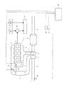
図1は、本実施例に係る内燃機関の制御システムを適用する内燃機関とその吸気系及び排気系の概略構成を模式的に示す概念図である。 FIG. 1 is a conceptual diagram schematically showing a schematic configuration of an internal combustion engine to which an internal combustion engine control system according to this embodiment is applied, and its intake system and exhaust system.
図1に示すエンジン1は、4個の気筒2を備え、各気筒2は吸気マニホールド5及び排気マニホールド6に連通している。
The
吸気マニホールド5には吸気通路3が接続されている。吸気通路3には排気マニホールド6と吸気通路3とを連通するEGR通路9が接続されている。EGR通路9の接続部より上流側の吸気通路3には、吸気通路3の流路面積を変更するスロットル弁23が備えられている。スロットル弁23の設置位置より上流側の吸気通路3には、吸気通路3を流通する吸気を冷却するインタークーラ11が備えられている。インタークーラ11の設置位置より上流側の吸気通路3には、過給機のコンプレッサ7が備えられている。コンプレッサ7の設置位置より上流側の吸気通路3には、吸入空気量を測定するエアフローメータ25が備えられている。
An
排気マニホールド6には排気通路4が接続されている。排気通路4には前記過給機のタービン8が備えられている。タービン8の設置位置より下流側の排気通路4には、排気浄化装置17が備えられている。排気浄化装置17は、排気中の微粒子物質を捕集するパティキュレートフィルタや、排気中のNOxを還元浄化する吸蔵還元型NOx触媒や、排気中のCOやHCを酸化する酸化触媒等の、公知の各種の排気浄化触媒を有して構成される。排気浄化装置17より下流側において排気通路4は大気に開放されている。
An
EGR通路9には、EGR通路9の流路面積を変更するEGR弁10が備えられている。EGR弁10が開弁されると、気筒2から排気マニホールド6に排出された排気の一部がEGR通路9を経由して吸気通路3に流入し、新気と排気との混合ガスが気筒2に吸入されるようになる。EGR通路9を介した吸気通路3への排気の導入を「排気再循環(EGR)」と称する。EGRを行うことにより、エンジン1の排気性能が向上する。
The
エンジン1には、エンジン1の運転状態を制御するコンピュータであるECU28が併設されている。ECU28には、上述したエアフローメータ25の他、エンジン1のクランクシャフトの回転角度を測定するクランク角度センサ22、アクセルペダルの踏み込み量を測定するアクセル開度センサ27、その他各種センサが電気的に接続され、これら各種センサによる測定データがECU28に入力される。また、ECU28には、上述したスロットル弁23やEGR弁10の他、各種機器が電気的に接続され、これら各種機器の動作を制御する信号がECU28から出力される。ECU28は各種センサから入力される測定データに基づいてエンジン1の運転状態及び制御要求を取得し、それに基づいて各種機器の動作を制御する。
The
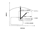
EGRが行われる運転条件はエンジン1の負荷及び回転数によって規定されている。図2には、EGRが行われる運転条件が負荷及び回転数により規定される領域で示されている。
The operating conditions under which EGR is performed are defined by the load and rotation speed of the
運転者がアクセルペダルを踏み込むと、その踏み込み量がアクセル開度センサ27により測定され、その測定値に応じてスロットル弁23の開度を増加させる制御がECU28により実行される。急加速時等にアクセルペダルが大きく踏み込まれると、スロットル弁23の開度を全開にする制御が行われる。スロットル弁23を全開にする制御をWOT(Wide Open Throttle)制御と称する。図2においてWOTラインと表記された曲線は、WOT制御においてスロットル弁23を全開にする場合に対応するエンジン1の機関負荷を表している。
When the driver depresses the accelerator pedal, the depression amount is measured by the
スロットル弁23の開度を増加させるとそれに伴って吸気圧力及び排気圧力が上昇するが、排気圧力は吸気圧力よりも遅れて上昇し始める。そのため、排気圧力が低い軽負荷の運転条件下におけるWOT制御によりスロットル弁23の開度が急激に増加させられると、吸気圧力が急激に上昇し、排気圧力の上昇が遅れている期間中に一時的に吸気圧力が排気圧力より高い状態が生じる場合がある。
When the opening degree of the
これについて図3に基づいて説明する。図3(A)に示すように、時刻t1においてアクセルペダルが大きく踏み込まれWOT制御要求が発生し、スロットル弁23の開度がDth1からDth2(全開)へ大幅に増加させられたとする(破線で示す)。そうすると、図3(C)に示すように、スロットル弁23の開度が増加させられた時刻t1の直後において吸気圧力がPin1から上昇し始める(破線で示す。Pin1はWOT制御要求発生前の軽負荷運転状態における吸気圧力)。これに対し、排気圧力は時刻t1より遅れたタイミングt3までは上昇せず、Pex1のままである(Pex1はWOT制御要求発生前の軽負荷運転状態における排気圧力)。そのため、スロットル弁23の大幅な開度増加に伴って急激に上昇した吸気圧力が、時刻t2において排気圧力Pex1を超える。そして時刻t4まで、吸気圧力が排気圧力より高い状態が生じることになる。
This will be described with reference to FIG. As shown in FIG. 3A, it is assumed that at time t1, the accelerator pedal is greatly depressed, a WOT control request is generated, and the opening degree of the
図2には、このようにWOT制御実行時に一時的に吸気圧力が排気圧力より高い状態が生じ得る運転条件を、上述したEGRが行われる運転条件と同様に、負荷及び回転数により規定される領域で示している。WOT制御時に吸気圧力が排気圧力より高くなる運転条件は、比較的軽負荷の運転領域である。以下この運転領域を「WOT時圧力反転領域」と称する。 In FIG. 2, the operating conditions in which the intake pressure may temporarily be higher than the exhaust pressure during execution of the WOT control are defined by the load and the rotational speed in the same manner as the operating conditions in which EGR is performed. Shown in area. The operating condition in which the intake pressure is higher than the exhaust pressure during WOT control is a relatively light load operating region. Hereinafter, this operation region is referred to as a “WOT pressure reversal region”.
図2に示されるように、EGR領域とWOT時圧力反転領域とは一部重なっている。図2ではこの重なった領域を斜線で示している。この重なった領域に属する運転条件においてWOT制御要求に応じてスロットル弁23の開度が急激に増加させられると、吸気圧力が排気圧力より高い状態が、EGR弁10が開弁状態とされている時に生じることになる。そうすると、EGR通路9を吸気通路3側から排気マニホールド6側へガスが逆流する可能性がある。吸気通路3内の空気がEGR通路9を逆流して排気マニホールド6に流入すると、空燃比にずれが生じて良好な燃焼が行われなくなったり、リーン空燃比のガスが意図せず排気浄化装置17に流入して触媒が劣化したりする虞がある。以下、EGR領域とWOT時圧力反転領域との共通部分の運転領域(図2で斜線で示された運転領域)を「WOT時逆流発生領域」と称する。
As shown in FIG. 2, the EGR region and the WOT pressure reversal region partially overlap each other. In FIG. 2, this overlapped area is indicated by hatching. When the opening degree of the
本実施例では、このWOT時逆流発生領域に属する運転条件S1においてWOT制御要求があった場合には、図2に示すように、WOT制御要求に対応して行われるエンジン1の制御における目標の運転状態として、WOTライン上に存在する本来の目標運転状態S
2を軽負荷且つ高回転側に補正した運転状態S2’を設定するようにした。
In this embodiment, when there is a WOT control request in the operating condition S1 belonging to this WOT backflow generation region, as shown in FIG. 2, the target of the control of the
An operation state S2 ′ in which 2 is corrected to a light load and high rotation side is set.
これにより、図3(A)に示すように、WOT制御要求に応じて行われるスロットル弁23の開弁制御において、WOTライン上の運転状態S2を目標として制御を行う場合の開度Dth2よりも閉じ側の開度Dth2’にすることができる。この開度Dth2’は、図3(C)に示すように、スロットル弁23の開度をDth1からDth2’まで増加させた場合に吸気圧力が排気圧力より高い状態が生じないような開度として定めることができる。このように、スロットル弁23の開弁開度を、吸気圧力が排気圧力より高い状態が生じない開度に制限することにより、EGR通路9に逆流が生じることを抑制することができる。従って、上述した空燃比ずれや触媒劣化の問題が生じることを回避できる。
Thereby, as shown in FIG. 3 (A), in the valve opening control of the
更に、図3(B)に示すように、WOT制御要求に対応するエンジン制御の本来の目標回転数Ne2よりも高い回転数Ne2’に制御されるので、上記のようにスロットル弁23の開弁開度に制限を設けることに起因してエンジン1の出力が要求出力に対して不足するような事態が生じないようにすることもできる。
Further, as shown in FIG. 3B, the
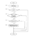
以上説明した本実施例におけるエンジン制御について、図4のフローチャートに基づいて説明する。図4のフローチャートで表される処理は、エンジン1の稼働中ECU28によって定期的に実行される。
The engine control in the present embodiment described above will be described based on the flowchart of FIG. The process represented by the flowchart of FIG. 4 is periodically executed by the
ステップS101において、ECU28は、エンジン1の運転状態を取得する。本実施例では、アクセル開度センサ27及びクランク角度センサ22から入力されるデータに基づき、エンジン1の機関負荷及び機関回転数を算出する。
In step S <b> 101, the
ステップS102及びステップS103において、ECU28は、エンジン1の運転状態がWOT時逆流発生領域に属しているか否かを判定する。まず、ステップS102において、ステップS101で取得したエンジン1の運転状態がEGR領域に属しているか否か判定し、肯定判定された場合、ステップS103において、ステップS101で取得したエンジン1の運転状態がWOT時圧力反転領域に属しているか否かを判定し、肯定判定された場合、ステップS104の処理に進む。ステップS102又はステップS103において否定判定された場合、ECU28はこのフローチャートの処理を抜ける。
In step S102 and step S103, the
ステップS104において、ECU28は、WOT制御要求があったか否かを判定する。本実施例ではアクセル開度センサ27によって測定されるアクセルペダルの踏み込み量が所定の閾値を超えたことが検知された場合に、WOT制御要求があったと判定する。ステップS104で肯定判定された場合、ECU28はステップS105の処理に進み、否定判定された場合はこのフローチャートの処理を抜ける。
In step S104, the
ステップS105において、ECU28は、WOT制御要求に対応するエンジン制御における本来の目標運状態(図2でWOTライン上に存在する運転状態S2)を、軽負荷且つ高回転数側に補正し、当該補正後の運転状態S2’を目標としてエンジン1の制御を行う。
In step S105, the
以上説明したフローチャートの処理を実行するECU28が、本発明における「制御手段」に相当する。本実施例においては、図2の斜線で示した「WOT時逆流発生領域」に属する運転条件が、本発明における「EGR通路を介して排気の再循環が行われ且つ機関負荷が所定負荷以下である運転条件」に相当する。また、本実施例におけるWOT制御要求が、本発明における「スロットル弁の開度を所定開度以上の開度まで開弁する要求を伴う制御要求」に相当する。
The
ECU28が上記のフローチャートで表される処理を行うことにより、EGRが行われている時にWOT制御要求があった場合においても、吸気通路3内の空気がEGR通路9を逆流することを抑制することが可能となる。
The
次に、本発明の実施例2を説明する。本実施例は、本発明に係る内燃機関の制御システムをハイブリッドシステムに適用した実施例である。 Next, a second embodiment of the present invention will be described. In this embodiment, the control system for an internal combustion engine according to the present invention is applied to a hybrid system.
図5に、本実施例に係るハイブリッドシステムの概略構成を模式的に示す。図1に示した実施例1の内燃機関との相違点は、エンジン1以外の動力源であるモータジェネレータMG1及びMG2と、MG1の出力及びエンジン1の出力を統合して駆動輪51に伝達する動力分割機構50と、を更に備え、ECU28はMG1及びMG2の回転数やトルクの制御を行う機能を更に有している点である。その他、バッテリやインバータ等の一般的なハイブリッドシステムと同様の構成を有するが、煩雑さを避けるためにここでは省略する。また、実施例1と同一の構成要素については実施例1と同一の名称及び符号を用いることとし、詳細な説明を省略する。
FIG. 5 schematically shows a schematic configuration of the hybrid system according to the present embodiment. The difference from the internal combustion engine of the first embodiment shown in FIG. 1 is that motor generators MG1 and MG2, which are power sources other than the
このようなハイブリッドシステムでは、エンジン1の機関回転数の制御自由度が高い。そこで、本実施例では、WOT時逆流発生領域に属する運転条件下でWOT制御要求があった場合に、WOTライン上に存在する本来の目標運転状態(図2のS2)より軽負荷且つ高回転の運転状態(図2のS2’)にまずエンジン1を制御するとともに、当該運転状態S2’からWOTライン上の本来の目標運転状態S2に向けて、徐々に運転状態を変化させていくようにエンジン1の制御を行うこととした。
In such a hybrid system, the degree of freedom in controlling the engine speed of the
図6に基づいて説明すると、図6(A)に示すように、時刻t1におけるWOT制御要求に応じて行われるスロットル弁23の開弁制御において、WOTライン上の運転状態S2を目標としてエンジン制御を行う場合の目標開度Dth2よりも閉じ側の開度Dth2’に開弁開度を制限するとともに、この開度Dth2’から本来の目標開度Dth2まで徐々にスロットル弁23の開度を増加させていく。
Explaining based on FIG. 6, as shown in FIG. 6A, in the valve opening control of the
これにより、吸気圧力が急激に上昇しないようにすることができるので、図6(C)に示すように、スロットル弁23の開弁制御に伴う圧力上昇の過程で、吸気圧力が排気圧力より高い状態が生じることを抑制できる。
As a result, the intake pressure can be prevented from abruptly increasing. Therefore, as shown in FIG. 6C, the intake pressure is higher than the exhaust pressure in the process of increasing the pressure accompanying the valve opening control of the
また、図6(B)に示すように、WOTライン上の運転状態S2を目標としてエンジン制御を行う場合の目標回転数Ne2よりも高回転側の回転数Ne2’に制御するとともに、この回転数Ne2’から本来の目標回転数Ne2まで徐々に機関回転数を低下させていく。 Further, as shown in FIG. 6 (B), the engine speed is controlled to a rotation speed Ne2 ′ higher than the target rotation speed Ne2 when the engine control is performed with the operation state S2 on the WOT line as a target. The engine speed is gradually reduced from Ne2 ′ to the original target speed Ne2.
これにより、WOT制御要求に対応する要求機関出力に対してエンジン1の出力に過不足が生じることを抑制することができる。
Thereby, it is possible to suppress an excess or deficiency in the output of the
以上説明した本実施例におけるエンジン制御について、図7のフローチャートに基づいて説明する。図7のフローチャートで表される処理は、エンジン1の稼働中ECU28によって定期的に実行される。
The engine control in the present embodiment described above will be described based on the flowchart of FIG. 7 is periodically executed by the
図7のフローチャートにおいて、ステップS101〜ステップS104までの処理内容は、実施例1において図4に基づいて説明したフローチャートと同一であるから、ここでは説明を省略する。 In the flowchart of FIG. 7, the processing contents from step S101 to step S104 are the same as the flowchart described based on FIG. 4 in the first embodiment, and thus the description thereof is omitted here.
図7のフローチャートでは、ステップS104において肯定判定された場合(すなわち、WOT時逆流発生領域に属する運転条件下でWOT制御要求が発生したと判定された場合)、ECU28は、ステップS205の処理に進み、まずWOTライン上に存在する本来の目標運転状態S2を軽負荷且つ高回転側に補正した運転状態S2’を目標としてエンジン1の制御を行うとともに、当該運転状態S2’から本来の目標運転状態S2に向けて徐々に運転状態を変化させるようにエンジン1を制御する。具体的には、図6で説明したように、スロットル弁23の開度を補正後の目標開度Dth2’から本来の目標開度Dth2に向けて徐々に増加させていくとともに、機関回転数を補正後の目標回転数Ne2’から本来の目標回転数Ne2に向けて徐々に減少させていく。
In the flowchart of FIG. 7, when an affirmative determination is made in step S104 (that is, when it is determined that a WOT control request has occurred under operating conditions belonging to the WOT backflow generation region), the
以上説明したフローチャートの処理を実行するECU28が、本発明における「制御手段」に相当する。
The
なお、本実施例では、WOT時逆流発生領域に属する運転条件下でWOT制御要求があった場合に、WOTライン上に存在する本来の目標運転状態S2より軽負荷且つ高回転側の運転状態S2’を目標としてまずエンジン制御を行う場合について説明したが、WOT制御要求の発生前の運転状態からWOTライン上の本来の目標運転状態S2に向けて徐々に運転状態を変化させるようにエンジン制御を行っても良い。 In this embodiment, when there is a WOT control request under the operating conditions belonging to the WOT backflow generation region, the operating state S2 is lighter and higher than the original target operating state S2 existing on the WOT line. In the above description, the engine control is first performed with 'as the target. However, the engine control is performed so that the operation state is gradually changed from the operation state before the generation of the WOT control request toward the original target operation state S2 on the WOT line. You can go.
なお、以上述べた実施例は本発明を説明するための一例であって、本発明の本旨を逸脱しない範囲内において上記の実施例には種々の変更を加え得る。例えば、WOT時逆流発生領域に属する運転条件下でWOT制御要求に応じてスロットル弁を全開にする場合以外にも、スロットル弁の開度を急激に増加させる場合には吸気圧力が排気圧力より一時的に高くなる可能性がある。従って、EGR領域に属する運転条件下で、所定の基準値以上の開度差のある開度までスロットル弁開度を増加させる制御要求があった場合に、本発明に係るエンジン制御を適用しても良い。ここで、「基準値」とは、スロットル弁の開弁に伴う圧力変化の過程で吸気圧力が排気圧力より高い状態が生じるか否かを判定するための開弁前後のスロットル弁の開度差の基準値である。 The above-described embodiment is an example for explaining the present invention, and various modifications can be made to the above-described embodiment without departing from the gist of the present invention. For example, in addition to fully opening the throttle valve in response to a WOT control request under operating conditions belonging to the WOT backflow generation region, when the throttle valve opening is suddenly increased, the intake pressure is temporarily higher than the exhaust pressure. Can be expensive. Therefore, the engine control according to the present invention is applied when there is a control request to increase the throttle valve opening to an opening having an opening difference that is greater than or equal to a predetermined reference value under operating conditions belonging to the EGR region. Also good. Here, the “reference value” is the difference in opening of the throttle valve before and after opening to determine whether or not the intake pressure is higher than the exhaust pressure in the process of pressure change accompanying the opening of the throttle valve. Is the reference value.
1 エンジン
2 気筒
3 吸気通路
4 排気通路
5 吸気マニホールド
6 排気マニホールド
7 コンプレッサ
8 タービン
9 EGR通路
10 EGR弁
11 インタークーラ
17 排気浄化装置
22 クランク角度センサ
23 スロットル弁
25 エアフローメータ
27 アクセル開度センサ
28 ECU
50 動力分割機構
51 駆動輪
1
50
Claims (2)
前記EGR通路の接続部より上流側の吸気通路に設けられたスロットル弁と、
前記EGR通路を介して排気の再循環が行われ且つ機関負荷が所定負荷以下である運転条件下において、前記スロットル弁の開度を所定開度以上の開度まで開弁する要求を伴う制御要求があった場合に、当該制御要求における目標の機関負荷よりも軽負荷且つ目標の機関回転数よりも高回転数の運転状態となるように前記内燃機関の制御を行う制御手段と、
を備えることを特徴とする内燃機関の制御システム。 An EGR passage communicating the exhaust passage and the intake passage of the internal combustion engine;
A throttle valve provided in an intake passage upstream of the connection portion of the EGR passage;
A control request with a request to open the throttle valve to an opening greater than or equal to a predetermined opening under operating conditions in which exhaust gas is recirculated through the EGR passage and the engine load is less than or equal to a predetermined load Control means for controlling the internal combustion engine so that the operating state is lighter than the target engine load and higher than the target engine speed in the control request,
An internal combustion engine control system comprising:
前記制御手段は、前記制御要求における目標の機関負荷よりも軽負荷の運転状態から当該目標の機関負荷の運転状態へ向けて徐々に機関負荷を高くするように前記内燃機関の制御を行うことを特徴とする内燃機関の制御システム。 In claim 1,
The control means controls the internal combustion engine so as to gradually increase the engine load from a light load operation state to a target engine load operation state than the target engine load in the control request. A control system for an internal combustion engine.
Priority Applications (1)
| Application Number | Priority Date | Filing Date | Title |
|---|---|---|---|
| JP2009089255A JP5146386B2 (en) | 2009-04-01 | 2009-04-01 | Internal combustion engine control system |
Applications Claiming Priority (1)
| Application Number | Priority Date | Filing Date | Title |
|---|---|---|---|
| JP2009089255A JP5146386B2 (en) | 2009-04-01 | 2009-04-01 | Internal combustion engine control system |
Publications (2)
| Publication Number | Publication Date |
|---|---|
| JP2010242514A true JP2010242514A (en) | 2010-10-28 |
| JP5146386B2 JP5146386B2 (en) | 2013-02-20 |
Family
ID=43095798
Family Applications (1)
| Application Number | Title | Priority Date | Filing Date |
|---|---|---|---|
| JP2009089255A Expired - Fee Related JP5146386B2 (en) | 2009-04-01 | 2009-04-01 | Internal combustion engine control system |
Country Status (1)
| Country | Link |
|---|---|
| JP (1) | JP5146386B2 (en) |
Cited By (2)
| Publication number | Priority date | Publication date | Assignee | Title |
|---|---|---|---|---|
| JP2016056802A (en) * | 2014-09-10 | 2016-04-21 | 日産自動車株式会社 | EGR control device |
| JP2016211532A (en) * | 2015-04-28 | 2016-12-15 | トヨタ自動車株式会社 | Control device for internal combustion engine |
Citations (2)
| Publication number | Priority date | Publication date | Assignee | Title |
|---|---|---|---|---|
| JP2003039990A (en) * | 2001-07-26 | 2003-02-13 | Toyota Motor Corp | Control device for vehicle with continuously variable transmission |
| JP2008296764A (en) * | 2007-05-31 | 2008-12-11 | Toyota Motor Corp | Hybrid vehicle |
-
2009
- 2009-04-01 JP JP2009089255A patent/JP5146386B2/en not_active Expired - Fee Related
Patent Citations (2)
| Publication number | Priority date | Publication date | Assignee | Title |
|---|---|---|---|---|
| JP2003039990A (en) * | 2001-07-26 | 2003-02-13 | Toyota Motor Corp | Control device for vehicle with continuously variable transmission |
| JP2008296764A (en) * | 2007-05-31 | 2008-12-11 | Toyota Motor Corp | Hybrid vehicle |
Cited By (2)
| Publication number | Priority date | Publication date | Assignee | Title |
|---|---|---|---|---|
| JP2016056802A (en) * | 2014-09-10 | 2016-04-21 | 日産自動車株式会社 | EGR control device |
| JP2016211532A (en) * | 2015-04-28 | 2016-12-15 | トヨタ自動車株式会社 | Control device for internal combustion engine |
Also Published As
| Publication number | Publication date |
|---|---|
| JP5146386B2 (en) | 2013-02-20 |
Similar Documents
| Publication | Publication Date | Title |
|---|---|---|
| US8190397B2 (en) | Failure diagnosis apparatus for exhaust pressure sensor | |
| US8065068B2 (en) | Vehicle control method and vehicle control device | |
| CN103380281B (en) | Controller and control method for internal combustion engine | |
| WO2008059362A2 (en) | Exhaust gas recirculation system for internal combustion engine and method for controlling the same | |
| WO2007142367A1 (en) | Exhaust gas purification system for internal combustion engine | |
| JP2008274836A (en) | Failure diagnostic device for intake air flow rate sensor | |
| JP5045339B2 (en) | Exhaust gas purification system for internal combustion engine | |
| JP4702322B2 (en) | Control device for internal combustion engine | |
| JP5287925B2 (en) | Turbocharger control device | |
| CN111417772A (en) | Control method and control device of internal combustion engine for vehicle | |
| JP5146386B2 (en) | Internal combustion engine control system | |
| WO2008068574A1 (en) | Egr system for internal combustion engine and method for controlling the same | |
| JP2014227844A (en) | Controller of internal combustion engine | |
| JP2012184738A (en) | Intake control device of internal combustion engine | |
| JP5858864B2 (en) | Engine control device | |
| US20230235709A1 (en) | Control method and control device for internal combustion engine | |
| JP2004346917A (en) | Internal combustion engine control device | |
| JP4281695B2 (en) | Control device for internal combustion engine | |
| JP6236893B2 (en) | Exhaust gas recirculation device and exhaust gas recirculation method for an internal combustion engine with a turbocharger | |
| JP4858237B2 (en) | Control device for internal combustion engine | |
| JP5040702B2 (en) | Control device for internal combustion engine | |
| JP2008038622A (en) | Exhaust purification device and method for internal combustion engine | |
| JP2009185757A (en) | Control device for internal combustion engine | |
| JP2009002278A (en) | Control device for internal combustion engine having supercharger | |
| JP2008008207A (en) | Exhaust gas recirculation device for internal combustion engine |
Legal Events
| Date | Code | Title | Description |
|---|---|---|---|
| A621 | Written request for application examination |
Free format text: JAPANESE INTERMEDIATE CODE: A621 Effective date: 20111222 |
|
| A977 | Report on retrieval |
Free format text: JAPANESE INTERMEDIATE CODE: A971007 Effective date: 20121026 |
|
| TRDD | Decision of grant or rejection written | ||
| A01 | Written decision to grant a patent or to grant a registration (utility model) |
Free format text: JAPANESE INTERMEDIATE CODE: A01 Effective date: 20121030 |
|
| A61 | First payment of annual fees (during grant procedure) |
Free format text: JAPANESE INTERMEDIATE CODE: A61 Effective date: 20121112 |
|
| R151 | Written notification of patent or utility model registration |
Ref document number: 5146386 Country of ref document: JP Free format text: JAPANESE INTERMEDIATE CODE: R151 |
|
| FPAY | Renewal fee payment (event date is renewal date of database) |
Free format text: PAYMENT UNTIL: 20151207 Year of fee payment: 3 |
|
| LAPS | Cancellation because of no payment of annual fees |