JP2010242573A - 燃料噴射弁及び燃料噴射弁の内部電気接続方法 - Google Patents
燃料噴射弁及び燃料噴射弁の内部電気接続方法 Download PDFInfo
- Publication number
- JP2010242573A JP2010242573A JP2009090733A JP2009090733A JP2010242573A JP 2010242573 A JP2010242573 A JP 2010242573A JP 2009090733 A JP2009090733 A JP 2009090733A JP 2009090733 A JP2009090733 A JP 2009090733A JP 2010242573 A JP2010242573 A JP 2010242573A
- Authority
- JP
- Japan
- Prior art keywords
- fuel
- pressure sensor
- sensor
- fuel pressure
- terminal
- Prior art date
- Legal status (The legal status is an assumption and is not a legal conclusion. Google has not performed a legal analysis and makes no representation as to the accuracy of the status listed.)
- Granted
Links
- 239000000446 fuel Substances 0.000 title claims abstract description 160
- 238000000034 method Methods 0.000 title claims description 12
- 230000002093 peripheral effect Effects 0.000 claims abstract description 25
- 238000002347 injection Methods 0.000 claims description 57
- 239000007924 injection Substances 0.000 claims description 57
- 238000001514 detection method Methods 0.000 claims description 14
- 238000002485 combustion reaction Methods 0.000 claims description 10
- 238000003466 welding Methods 0.000 claims description 10
- 239000011347 resin Substances 0.000 claims description 9
- 229920005989 resin Polymers 0.000 claims description 9
- 238000007789 sealing Methods 0.000 claims 1
- 238000004804 winding Methods 0.000 description 14
- 238000009413 insulation Methods 0.000 description 6
- 239000002184 metal Substances 0.000 description 3
- 230000008602 contraction Effects 0.000 description 2
- 230000000694 effects Effects 0.000 description 2
- 239000003502 gasoline Substances 0.000 description 2
- 238000003780 insertion Methods 0.000 description 2
- 230000037431 insertion Effects 0.000 description 2
- WABPQHHGFIMREM-UHFFFAOYSA-N lead(0) Chemical compound [Pb] WABPQHHGFIMREM-UHFFFAOYSA-N 0.000 description 2
- 238000000465 moulding Methods 0.000 description 2
- 238000009825 accumulation Methods 0.000 description 1
- 230000003321 amplification Effects 0.000 description 1
- 239000000872 buffer Substances 0.000 description 1
- 239000011248 coating agent Substances 0.000 description 1
- 238000000576 coating method Methods 0.000 description 1
- 238000007599 discharging Methods 0.000 description 1
- 230000005489 elastic deformation Effects 0.000 description 1
- 238000009429 electrical wiring Methods 0.000 description 1
- 238000001914 filtration Methods 0.000 description 1
- 239000002828 fuel tank Substances 0.000 description 1
- 239000011521 glass Substances 0.000 description 1
- 230000002452 interceptive effect Effects 0.000 description 1
- 238000010030 laminating Methods 0.000 description 1
- 239000000203 mixture Substances 0.000 description 1
- 238000003199 nucleic acid amplification method Methods 0.000 description 1
- 238000005476 soldering Methods 0.000 description 1
Images


Classifications
-
- F—MECHANICAL ENGINEERING; LIGHTING; HEATING; WEAPONS; BLASTING
- F02—COMBUSTION ENGINES; HOT-GAS OR COMBUSTION-PRODUCT ENGINE PLANTS
- F02M—SUPPLYING COMBUSTION ENGINES IN GENERAL WITH COMBUSTIBLE MIXTURES OR CONSTITUENTS THEREOF
- F02M57/00—Fuel-injectors combined or associated with other devices
- F02M57/005—Fuel-injectors combined or associated with other devices the devices being sensors
-
- F—MECHANICAL ENGINEERING; LIGHTING; HEATING; WEAPONS; BLASTING
- F02—COMBUSTION ENGINES; HOT-GAS OR COMBUSTION-PRODUCT ENGINE PLANTS
- F02M—SUPPLYING COMBUSTION ENGINES IN GENERAL WITH COMBUSTIBLE MIXTURES OR CONSTITUENTS THEREOF
- F02M51/00—Fuel-injection apparatus characterised by being operated electrically
- F02M51/005—Arrangement of electrical wires and connections, e.g. wire harness, sockets, plugs; Arrangement of electronic control circuits in or on fuel injection apparatus
-
- F—MECHANICAL ENGINEERING; LIGHTING; HEATING; WEAPONS; BLASTING
- F02—COMBUSTION ENGINES; HOT-GAS OR COMBUSTION-PRODUCT ENGINE PLANTS
- F02M—SUPPLYING COMBUSTION ENGINES IN GENERAL WITH COMBUSTIBLE MIXTURES OR CONSTITUENTS THEREOF
- F02M61/00—Fuel-injectors not provided for in groups F02M39/00 - F02M57/00 or F02M67/00
- F02M61/16—Details not provided for in, or of interest apart from, the apparatus of groups F02M61/02 - F02M61/14
- F02M61/168—Assembling; Disassembling; Manufacturing; Adjusting
-
- F—MECHANICAL ENGINEERING; LIGHTING; HEATING; WEAPONS; BLASTING
- F02—COMBUSTION ENGINES; HOT-GAS OR COMBUSTION-PRODUCT ENGINE PLANTS
- F02M—SUPPLYING COMBUSTION ENGINES IN GENERAL WITH COMBUSTIBLE MIXTURES OR CONSTITUENTS THEREOF
- F02M2200/00—Details of fuel-injection apparatus, not otherwise provided for
- F02M2200/24—Fuel-injection apparatus with sensors
-
- F—MECHANICAL ENGINEERING; LIGHTING; HEATING; WEAPONS; BLASTING
- F02—COMBUSTION ENGINES; HOT-GAS OR COMBUSTION-PRODUCT ENGINE PLANTS
- F02M—SUPPLYING COMBUSTION ENGINES IN GENERAL WITH COMBUSTIBLE MIXTURES OR CONSTITUENTS THEREOF
- F02M2200/00—Details of fuel-injection apparatus, not otherwise provided for
- F02M2200/80—Fuel injection apparatus manufacture, repair or assembly
- F02M2200/8046—Fuel injection apparatus manufacture, repair or assembly the manufacture involving injection moulding, e.g. of plastic or metal
-
- F—MECHANICAL ENGINEERING; LIGHTING; HEATING; WEAPONS; BLASTING
- F02—COMBUSTION ENGINES; HOT-GAS OR COMBUSTION-PRODUCT ENGINE PLANTS
- F02M—SUPPLYING COMBUSTION ENGINES IN GENERAL WITH COMBUSTIBLE MIXTURES OR CONSTITUENTS THEREOF
- F02M2200/00—Details of fuel-injection apparatus, not otherwise provided for
- F02M2200/80—Fuel injection apparatus manufacture, repair or assembly
- F02M2200/8076—Fuel injection apparatus manufacture, repair or assembly involving threaded members
Landscapes
- Engineering & Computer Science (AREA)
- Chemical & Material Sciences (AREA)
- Combustion & Propulsion (AREA)
- Mechanical Engineering (AREA)
- General Engineering & Computer Science (AREA)
- Manufacturing & Machinery (AREA)
- Analytical Chemistry (AREA)
- Fuel-Injection Apparatus (AREA)
- Combined Controls Of Internal Combustion Engines (AREA)
Abstract
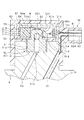
【解決手段】インジェクタボデーに取り付けられる燃圧センサ51,52と、燃圧センサに設けられた複数のセンサ端子54b〜54eと、前記ボデーに取り付けられたコネクタを構成する複数のセンサ用コネクタ端子63b〜63eと、両端子63b〜63e,54b〜54eの各々を電気接続する複数本の電線71b〜71eと、を備え、燃圧センサは、センサ端子とともに回転してボデーと螺子締結される螺子部51dを有している。そして、燃圧センサを包囲するよう設けられるボビン55(係止部材)は、螺子部51dによって回転して螺子締結された燃圧センサのセンサ端子と電気接続する電線を、燃圧センサの外周側で係止する。
【選択図】 図3
Description
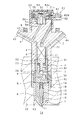
本発明の第1実施形態について図1〜図5を用いて説明する。図1は本実施形態に係るインジェクタ(燃料噴射弁)の概略内部構成を示す模式的な断面図であり、先ずこの図1に基づいて、インジェクタの基本的な構成、作動について説明する。
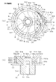
図4は、ボビン55単体を示す2面図であり、ボビン55は、モールド樹脂54mの外周面に沿って延びる円弧状に形成され、センサ端子54c,54dと対向する位置に開口部55aを有する形状である。ボビン55の上端位置は、モールドIC54の上端位置及び歪ゲージ52と同じである。
上記第1実施形態では、ボビン55の外周側壁を、電線71b〜71eの巻き回される方向(燃圧センサ50の回転周方向)に沿って円弧状に延びる形状に形成しているのに対し、図6に示す本実施形態では、ボビン55の外周側壁を多角形状に形成している。例えば、インジェクタの軸方向から見て、図6(a)に示すように四角形に形成する。或いは、図6(b)に示すように六角形に形成する。またはそれ以上の多角形でも良い。
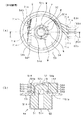
上記第1実施形態では、係止部材の形状を、電線71b〜71eが巻き回される方向(燃圧センサ50の回転周方向)に沿って延びて電線71b〜71eと、その外周で線接触するボビン55の形状(筒形状)としている。これに対し、図7に示す本実施形態では、係止部材の形状を、電線71b〜71eの巻き回される方向(燃圧センサ50の回転周方向)に複数配置されたピン552の形状としており、これらのピン552は、電線71b〜71eと点接触する。
図8に示すように本実施形態では、上記ボビン55やピン552を廃止しており、燃圧センサ50の外周に円弧状に延びるように形成されたモールドIC54に電線71b〜71eを巻き回して係止させている。すなわち、センサ素子52を包囲するよう形成されるモールドIC54の外周側壁面を円弧状に形成することで、燃圧センサ50の外周に電線71b〜71eを巻き回して係止させている。このように、モールドIC54を係止部材として機能させている。また、本実施形態においても上記第1実施形態の溝部55b〜55eと同様にして、外周面に溝部54gを形成している。
本発明は上記実施形態の記載内容に限定されず、以下のように変更して実施してもよい。また、各実施形態の特徴的構成をそれぞれ任意に組み合わせるようにしてもよい。
Claims (11)
- 内燃機関に搭載されて噴孔から燃料を噴射する燃料噴射弁において、
前記噴孔へ高圧燃料を流通させる高圧通路を内部に形成するボデーと、
前記ボデーに取り付けられて前記高圧燃料の圧力を検出する燃圧センサと、
前記燃圧センサに設けられ、前記燃圧センサの検出信号を出力する端子を少なくとも含む複数のセンサ端子と、
前記ボデーの特定位置に取り付けられたコネクタハウジングに保持されている複数のコネクタ端子と、
前記コネクタ端子及び前記センサ端子の各々を電気接続する複数本の電線と、
を備え、
前記燃圧センサは、前記センサ端子とともに回転して前記ボデーと螺子締結される螺子部を有しており、
前記燃圧センサを包囲するよう設けられる係止部材であって、
この係止部材は、前記螺子部によって回転して前記ボデーに螺子締結された前記燃圧センサの前記センサ端子と電気接続する前記電線を係止し、係止された前記電線を前記コネクタ端子に電気接続させることを特徴とする燃料噴射弁。 - 前記係止部材は、前記燃圧センサの回転周方向に延び、前記電線と線接触する形状であることを特徴とする請求項1に記載の燃料噴射弁。
- 前記係止部材は、前記燃圧センサの回転周方向に円弧状に延びる形状であることを特徴とする請求項2に記載の燃料噴射弁。
- 前記係止部材は、前記センサ端子と対向する位置に開口部が形成された形状であり、
前記電線は、前記開口部を通るよう配置されるとともに、前記係止部材のうち前記開口部の端部を始点又は終点として、その外周に沿って配置されていることを特徴とする請求項2又は3に記載の燃料噴射弁。 - 前記係止部材は、前記燃圧センサの回転周方向に沿って複数配置されて前記電線と点接触する形状であることを特徴とする請求項1に記載の燃料噴射弁。
- 前記係止部材には、前記電線を嵌め込む溝部が、前記燃圧センサの回転中心方向に複数並べて形成されていることを特徴とする請求項1〜5のいずれか1つに記載の燃料噴射弁。
- 前記高圧通路を開閉するニードルを駆動させるための駆動手段、及び前記駆動手段に電力供給する駆動端子を備え、
前記駆動端子を前記コネクタハウジングに保持させることで、前記コネクタ端子及び前記駆動端子を共通のコネクタに構成したことを特徴とする請求項1〜6のいずれか1つに記載の燃料噴射弁。 - 前記燃圧センサは、
前記高圧燃料を内部に導入する導入口が一端に形成された円筒形状の円筒部と、
前記円筒部の他端を閉塞するよう位置し、前記高圧燃料の圧力を受けて弾性変形する円板形状のダイヤフラム部と、
前記ダイヤフラム部に取り付けられ、前記ダイヤフラム部にて生じた歪の大きさを電気信号に変換して前記検出信号として出力するセンサ素子と、
を有して構成され、
前記螺子部は、前記円筒部の外周面に形成されていることを特徴とする請求項1〜7のいずれか1つに記載の燃料噴射弁。 - 前記係止部材は、前記螺子締結の時に前記燃圧センサとともに回転するよう構成されていることを特徴とする請求項1〜8のいずれか1つに記載の燃料噴射弁。
- 前記燃圧センサから出力される検出信号を増幅する電子部品を、モールド樹脂で封止して構成されたモールド体を備え、
前記モールド体を前記燃圧センサの回転周方向に延びる形状に形成するとともに、
前記モールド体を、前記電線が係止される前記係止部材としたことを特徴とする請求項1〜9のいずれか1つに記載の燃料噴射弁。 - 請求項1〜10のいずれか1つに記載の燃料噴射弁の内部電気接続方法であって、
前記燃圧センサを前記センサ端子とともに回転させて、前記燃圧センサを前記ボデーに螺子締結させる締結工程と、
前記締結工程の後、前記コネクタ端子及び前記センサ端子のいずれか一方に前記電線を電気接続する第1接続工程と、
前記第1接続工程の後、前記係止部材に前記電線を係止させる係止工程と、
前記係止工程の後、前記コネクタ端子及び前記センサ端子の他方に前記電線を溶接する第2接続工程と、
を含むことを特徴とする燃料噴射弁の内部電気接続方法。
Priority Applications (3)
| Application Number | Priority Date | Filing Date | Title |
|---|---|---|---|
| JP2009090733A JP5154495B2 (ja) | 2009-04-03 | 2009-04-03 | 燃料噴射弁及び燃料噴射弁の内部電気接続方法 |
| DE102010016298.1A DE102010016298B4 (de) | 2009-04-03 | 2010-04-01 | Kraftstoffeinspritzvorrichtung mit Kraftstoffdrucksensor und Verfahren zu ihrer elektrischen Verbindung |
| US12/753,287 US8905003B2 (en) | 2009-04-03 | 2010-04-02 | Fuel injector with fuel pressure sensor and electrical interconnection method of the same |
Applications Claiming Priority (1)
| Application Number | Priority Date | Filing Date | Title |
|---|---|---|---|
| JP2009090733A JP5154495B2 (ja) | 2009-04-03 | 2009-04-03 | 燃料噴射弁及び燃料噴射弁の内部電気接続方法 |
Publications (2)
| Publication Number | Publication Date |
|---|---|
| JP2010242573A true JP2010242573A (ja) | 2010-10-28 |
| JP5154495B2 JP5154495B2 (ja) | 2013-02-27 |
Family
ID=42825138
Family Applications (1)
| Application Number | Title | Priority Date | Filing Date |
|---|---|---|---|
| JP2009090733A Expired - Fee Related JP5154495B2 (ja) | 2009-04-03 | 2009-04-03 | 燃料噴射弁及び燃料噴射弁の内部電気接続方法 |
Country Status (3)
| Country | Link |
|---|---|
| US (1) | US8905003B2 (ja) |
| JP (1) | JP5154495B2 (ja) |
| DE (1) | DE102010016298B4 (ja) |
Families Citing this family (10)
| Publication number | Priority date | Publication date | Assignee | Title |
|---|---|---|---|---|
| JP5064341B2 (ja) * | 2007-11-02 | 2012-10-31 | 株式会社デンソー | 燃料噴射弁及び燃料噴射装置 |
| JP5383132B2 (ja) * | 2008-03-28 | 2014-01-08 | 株式会社デンソー | 燃圧センサ搭載構造、燃圧検出システム、燃料噴射装置、それに用いられる圧力検出装置及び蓄圧式燃料噴射装置システム |
| JP5120318B2 (ja) * | 2009-04-03 | 2013-01-16 | 株式会社デンソー | 燃料噴射弁 |
| US9587612B2 (en) * | 2011-02-25 | 2017-03-07 | Honda Motor Co., Ltd. | In-cylinder pressure detecting device of direct injection type internal combustion engine |
| WO2013036318A1 (en) * | 2011-09-08 | 2013-03-14 | International Engine Intellectual Property Company, Llc | Fuel injector solenoid and terminal assembly |
| WO2015011058A1 (en) * | 2013-07-26 | 2015-01-29 | Robert Bosch Gmbh | An injector for internal combustion engines |
| US9281114B2 (en) * | 2014-03-11 | 2016-03-08 | Buescher Developments, Llc | Stator for electronic fuel injector |
| DE102014223661A1 (de) * | 2014-11-20 | 2016-05-25 | Robert Bosch Gmbh | Kraftstoffinjektor |
| DE102015201970A1 (de) * | 2015-02-04 | 2016-08-04 | Robert Bosch Gmbh | Bauteileverbund, Verfahren zum Herstellen eines Bauteileverbunds und Kraftstoffinjektor |
| DE102015207307A1 (de) * | 2015-04-22 | 2016-10-27 | Robert Bosch Gmbh | Kraftstoffinjektor |
Citations (9)
| Publication number | Priority date | Publication date | Assignee | Title |
|---|---|---|---|---|
| JPS5537971A (en) * | 1978-09-11 | 1980-03-17 | Agency Of Ind Science & Technol | Fuel-injection-timing detector of diesel engine |
| JPS56118553A (en) * | 1980-02-22 | 1981-09-17 | Toyota Motor Corp | Fuel injection time detection device for diesel engine |
| JPH1064649A (ja) * | 1996-08-22 | 1998-03-06 | Nec Yonezawa Ltd | 電気接続コネクタ |
| JPH11299182A (ja) * | 1998-04-17 | 1999-10-29 | Dainippon Printing Co Ltd | スリップリング及びスリップリングの駆動方法 |
| JP2000161176A (ja) * | 1998-11-30 | 2000-06-13 | Denso Corp | 圧電式制御弁 |
| JP2001189183A (ja) * | 2000-01-06 | 2001-07-10 | Ricoh Co Ltd | 集電装置 |
| JP2005172761A (ja) * | 2003-12-15 | 2005-06-30 | Denso Corp | 圧力センサ |
| JP2007265847A (ja) * | 2006-03-29 | 2007-10-11 | Japan Servo Co Ltd | 摺動リングを用いた接続端子を備えるスリップリング |
| WO2009019663A2 (en) * | 2007-08-07 | 2009-02-12 | Delphi Technologies, Inc. | Fuel injector and method for controlling fuel injectors |
Family Cites Families (29)
| Publication number | Priority date | Publication date | Assignee | Title |
|---|---|---|---|---|
| US4373671A (en) * | 1981-04-13 | 1983-02-15 | Ford Motor Company | Electromagnetic fuel injector |
| DE3441140A1 (de) | 1984-11-10 | 1986-05-15 | Robert Bosch Gmbh, 7000 Stuttgart | Einrichtung zum einspritzen von kraftstoff in brennraeume von brennkraftmaschinen |
| US4630465A (en) * | 1984-11-19 | 1986-12-23 | Eaton Corporation | Low viscous drag knock sensor |
| US5129834A (en) * | 1991-03-04 | 1992-07-14 | Siemens Automotive L.P. | Multiple function electrical connector for connecting to a fuel-rail-mounted fuel injector |
| US6260537B1 (en) * | 1998-02-20 | 2001-07-17 | Delphi Technologies, Inc. | Side feed fuel injector and integrated fuel rail/intake manifold |
| US6590162B1 (en) * | 2002-07-16 | 2003-07-08 | Siemens Diesel Systems Technology | Wire guide |
| DE10236505B4 (de) * | 2002-08-09 | 2007-09-06 | Mtu Friedrichshafen Gmbh | Brennkraftmaschine mit einem Verbindungsmittel zum Verbinden eines ersten mit einem zweiten Abschnitt eines Kabelbaums an einem Zylinderkopf-Gehäuse |
| JP4774678B2 (ja) * | 2003-08-29 | 2011-09-14 | 富士電機株式会社 | 圧力センサ装置 |
| US7040149B2 (en) * | 2003-10-24 | 2006-05-09 | Senx Technology, Llc | Fuel injection system diagnostic system |
| JP2005257442A (ja) * | 2004-03-11 | 2005-09-22 | Denso Corp | 圧力センサ |
| DE102005024194A1 (de) | 2005-05-25 | 2006-11-30 | Siemens Ag | Einspritzventil und Einspritzvorrichtung für eine Brennkraftmaschine und Brennkraftmaschine |
| GB0609519D0 (en) * | 2006-05-12 | 2006-06-21 | Delphi Tech Inc | Fuel injector |
| JP4840288B2 (ja) | 2006-11-14 | 2011-12-21 | 株式会社デンソー | 燃料噴射装置及びその調整方法 |
| JP4547410B2 (ja) | 2007-10-04 | 2010-09-22 | 本田技研工業株式会社 | ステアリングハンガービーム |
| JP5064341B2 (ja) * | 2007-11-02 | 2012-10-31 | 株式会社デンソー | 燃料噴射弁及び燃料噴射装置 |
| JP5079643B2 (ja) * | 2007-11-02 | 2012-11-21 | 株式会社デンソー | 燃料噴射弁及び燃料噴射装置 |
| JP5044368B2 (ja) * | 2007-11-06 | 2012-10-10 | 株式会社デンソー | 燃料噴射弁 |
| JP4954848B2 (ja) * | 2007-11-06 | 2012-06-20 | 株式会社デンソー | 燃料噴射弁 |
| JP4959509B2 (ja) * | 2007-11-06 | 2012-06-27 | 株式会社デンソー | 燃料噴射弁 |
| JP4894804B2 (ja) * | 2008-03-28 | 2012-03-14 | 株式会社デンソー | 燃料噴射弁 |
| JP4840391B2 (ja) * | 2008-03-28 | 2011-12-21 | 株式会社デンソー | 燃圧センサ搭載構造及び燃圧検出システム |
| JP5383132B2 (ja) * | 2008-03-28 | 2014-01-08 | 株式会社デンソー | 燃圧センサ搭載構造、燃圧検出システム、燃料噴射装置、それに用いられる圧力検出装置及び蓄圧式燃料噴射装置システム |
| JP5195451B2 (ja) * | 2008-04-15 | 2013-05-08 | 株式会社デンソー | 燃料噴射装置、それに用いられる蓄圧式燃料噴射装置システム |
| JP5265439B2 (ja) * | 2009-04-03 | 2013-08-14 | 株式会社デンソー | 燃料噴射弁 |
| JP5169951B2 (ja) * | 2009-04-03 | 2013-03-27 | 株式会社デンソー | 燃料噴射弁 |
| JP5104806B2 (ja) * | 2009-04-03 | 2012-12-19 | 株式会社デンソー | 燃料噴射弁及び燃料噴射弁の製造方法 |
| JP5220674B2 (ja) * | 2009-04-03 | 2013-06-26 | 株式会社デンソー | 燃料噴射弁及び燃料噴射弁の内部電気接続方法 |
| JP5120318B2 (ja) * | 2009-04-03 | 2013-01-16 | 株式会社デンソー | 燃料噴射弁 |
| JP5262948B2 (ja) * | 2009-04-20 | 2013-08-14 | 株式会社デンソー | 燃料噴射弁 |
-
2009
- 2009-04-03 JP JP2009090733A patent/JP5154495B2/ja not_active Expired - Fee Related
-
2010
- 2010-04-01 DE DE102010016298.1A patent/DE102010016298B4/de not_active Expired - Fee Related
- 2010-04-02 US US12/753,287 patent/US8905003B2/en not_active Expired - Fee Related
Patent Citations (9)
| Publication number | Priority date | Publication date | Assignee | Title |
|---|---|---|---|---|
| JPS5537971A (en) * | 1978-09-11 | 1980-03-17 | Agency Of Ind Science & Technol | Fuel-injection-timing detector of diesel engine |
| JPS56118553A (en) * | 1980-02-22 | 1981-09-17 | Toyota Motor Corp | Fuel injection time detection device for diesel engine |
| JPH1064649A (ja) * | 1996-08-22 | 1998-03-06 | Nec Yonezawa Ltd | 電気接続コネクタ |
| JPH11299182A (ja) * | 1998-04-17 | 1999-10-29 | Dainippon Printing Co Ltd | スリップリング及びスリップリングの駆動方法 |
| JP2000161176A (ja) * | 1998-11-30 | 2000-06-13 | Denso Corp | 圧電式制御弁 |
| JP2001189183A (ja) * | 2000-01-06 | 2001-07-10 | Ricoh Co Ltd | 集電装置 |
| JP2005172761A (ja) * | 2003-12-15 | 2005-06-30 | Denso Corp | 圧力センサ |
| JP2007265847A (ja) * | 2006-03-29 | 2007-10-11 | Japan Servo Co Ltd | 摺動リングを用いた接続端子を備えるスリップリング |
| WO2009019663A2 (en) * | 2007-08-07 | 2009-02-12 | Delphi Technologies, Inc. | Fuel injector and method for controlling fuel injectors |
Also Published As
| Publication number | Publication date |
|---|---|
| US8905003B2 (en) | 2014-12-09 |
| US20100252001A1 (en) | 2010-10-07 |
| JP5154495B2 (ja) | 2013-02-27 |
| DE102010016298B4 (de) | 2021-12-30 |
| DE102010016298A1 (de) | 2010-11-11 |
Similar Documents
| Publication | Publication Date | Title |
|---|---|---|
| JP5154495B2 (ja) | 燃料噴射弁及び燃料噴射弁の内部電気接続方法 | |
| JP5220674B2 (ja) | 燃料噴射弁及び燃料噴射弁の内部電気接続方法 | |
| JP5265439B2 (ja) | 燃料噴射弁 | |
| JP5169951B2 (ja) | 燃料噴射弁 | |
| JP5044368B2 (ja) | 燃料噴射弁 | |
| JP5169950B2 (ja) | 燃料噴射弁 | |
| JP4959509B2 (ja) | 燃料噴射弁 | |
| JP6175059B2 (ja) | 燃料噴射装置 | |
| JP2010249061A (ja) | 燃料噴射弁 | |
| US20080265716A1 (en) | Piezoelectric actuator with a sheath, for disposition in a piezoelectric injector | |
| JP2010255427A (ja) | 燃料噴射弁 | |
| JP2009236102A (ja) | 燃料噴射弁 | |
| JP5104806B2 (ja) | 燃料噴射弁及び燃料噴射弁の製造方法 | |
| JP6503190B2 (ja) | 筒内圧センサ付き燃料噴射弁 | |
| JP5120318B2 (ja) | 燃料噴射弁 | |
| JP5262948B2 (ja) | 燃料噴射弁 | |
| JP5240019B2 (ja) | 燃料噴射弁及び燃料噴射弁の内部電気接続方法 | |
| JP2010255426A (ja) | 燃料噴射弁 | |
| JP2016133072A (ja) | 筒内圧センサ付き燃料噴射弁 | |
| JP2016133065A (ja) | 筒内圧センサ付き燃料噴射弁 | |
| JP5500110B2 (ja) | センサ装置 | |
| JP2016133069A (ja) | 筒内圧センサ付き燃料噴射弁 | |
| JP4375291B2 (ja) | 燃料噴射弁およびその製造方法 |
Legal Events
| Date | Code | Title | Description |
|---|---|---|---|
| A621 | Written request for application examination |
Free format text: JAPANESE INTERMEDIATE CODE: A621 Effective date: 20111003 |
|
| A977 | Report on retrieval |
Free format text: JAPANESE INTERMEDIATE CODE: A971007 Effective date: 20121026 |
|
| TRDD | Decision of grant or rejection written | ||
| A01 | Written decision to grant a patent or to grant a registration (utility model) |
Free format text: JAPANESE INTERMEDIATE CODE: A01 Effective date: 20121106 |
|
| A61 | First payment of annual fees (during grant procedure) |
Free format text: JAPANESE INTERMEDIATE CODE: A61 Effective date: 20121205 |
|
| FPAY | Renewal fee payment (event date is renewal date of database) |
Free format text: PAYMENT UNTIL: 20151214 Year of fee payment: 3 |
|
| R150 | Certificate of patent or registration of utility model |
Free format text: JAPANESE INTERMEDIATE CODE: R150 |
|
| LAPS | Cancellation because of no payment of annual fees |