JP2010247238A - Parallel link stage and optical element measuring instrument - Google Patents
Parallel link stage and optical element measuring instrument Download PDFInfo
- Publication number
- JP2010247238A JP2010247238A JP2009095914A JP2009095914A JP2010247238A JP 2010247238 A JP2010247238 A JP 2010247238A JP 2009095914 A JP2009095914 A JP 2009095914A JP 2009095914 A JP2009095914 A JP 2009095914A JP 2010247238 A JP2010247238 A JP 2010247238A
- Authority
- JP
- Japan
- Prior art keywords
- parallel link
- movable member
- rotation
- rotation axis
- turntable
- Prior art date
- Legal status (The legal status is an assumption and is not a legal conclusion. Google has not performed a legal analysis and makes no representation as to the accuracy of the status listed.)
- Withdrawn
Links
- 230000003287 optical effect Effects 0.000 title claims abstract description 65
- 230000007246 mechanism Effects 0.000 claims abstract description 71
- 230000000149 penetrating effect Effects 0.000 claims description 6
- 230000033001 locomotion Effects 0.000 abstract description 40
- 230000008859 change Effects 0.000 abstract description 5
- 230000002093 peripheral effect Effects 0.000 description 38
- 238000005259 measurement Methods 0.000 description 24
- 230000006870 function Effects 0.000 description 3
- 238000000034 method Methods 0.000 description 3
- 230000005540 biological transmission Effects 0.000 description 2
- 230000008878 coupling Effects 0.000 description 2
- 238000010168 coupling process Methods 0.000 description 2
- 238000005859 coupling reaction Methods 0.000 description 2
- 238000010586 diagram Methods 0.000 description 2
- 230000008602 contraction Effects 0.000 description 1
- 238000001514 detection method Methods 0.000 description 1
- 239000012636 effector Substances 0.000 description 1
- 238000009434 installation Methods 0.000 description 1
- 230000002452 interceptive effect Effects 0.000 description 1
- 238000012423 maintenance Methods 0.000 description 1
- 230000007935 neutral effect Effects 0.000 description 1
- 230000008569 process Effects 0.000 description 1
- 238000005476 soldering Methods 0.000 description 1
- 230000001360 synchronised effect Effects 0.000 description 1
Images

Landscapes
- Machine Tool Units (AREA)
- Manipulator (AREA)
- Transmission Devices (AREA)
Abstract
Description
本発明は、パラレルリンクステージおよび光学素子測定装置に関する。 The present invention relates to a parallel link stage and an optical element measuring apparatus.
基台と可動部材(エンドエフェクタ)とが複数の駆動軸によって並列に接続されているパラレルリンク機構としては、複数本の直線状の駆動軸を伸縮させて可動部材の位置および姿勢を制御する構成のスチュワートプラットフォーム型が広く知られている。このうち駆動軸が基台および可動部材の周方向に6本設けられているものは、並進3自由度と回転3自由度の計6自由度の相対運動が可能である。このようなパラレルリンク機構は、可動部材上にワークや被測定体を配置して、基台に対するワークや被測定体の位置および姿勢を制御するパラレルリンクステージとして用いられている。なお、駆動軸の代わりに固定長のリンクで、リンクの連結部をアクチュエータで回転、あるいは直進駆動させることでパラレルリンク機構を構成したものも知られている。
このような構成のパラレルリンクステージは、例えば、多関節ロボット等のシリアルリンク機構と比較して、高い剛性、高精度位置決めなどを有しているものの、可動範囲は狭くなっていた。特に、パラレレリンク機構の並列方向に沿う回転範囲が狭いため、可動部材上に保持されたワークや被測定体を、可動部材の法線回りあるいは基台の法線回りに回転させようとすると、あまり大きな回転範囲がとれないという問題があった。
このため、従来、可動部材に保持するワークや被測定体等の可動部材を法線回りあるいは基台の法線回りの回転範囲を増大させることができるパラレルリンクステージが提案されている。
このようなパラレルリンクステージとして、例えば、特許文献1には、パラレルリンク機構によるロール軸回りの回転角を増幅するロール軸回転角増幅機を備えることで、ロール軸回りの回転範囲を増大させた駆動装置が提案されている。
また、特許文献2には、ツール等の可動部材やテーブルを取り付けるための出力フランジ(装着部)を移動板上に回転可能に配備し、出力フランジを回転させるための駆動装置となるサーボモータを移動板に一体的に組み込んで配備することで、回転自由度を向上させたパラレルリンク機構が提案されている。
A parallel link mechanism in which a base and a movable member (end effector) are connected in parallel by a plurality of drive shafts is configured to extend and contract a plurality of linear drive shafts to control the position and posture of the movable member. The Stewart platform type is widely known. Of these, those having six drive shafts in the circumferential direction of the base and the movable member are capable of relative motion with a total of six degrees of freedom, including three degrees of freedom of translation and three degrees of freedom of rotation. Such a parallel link mechanism is used as a parallel link stage in which a work and a measured object are arranged on a movable member and the position and posture of the work and the measured object with respect to a base are controlled. It is also known that a parallel link mechanism is configured by using a fixed-length link instead of the drive shaft and rotating or connecting the link connecting portion with an actuator.
The parallel link stage having such a configuration has high rigidity and high-precision positioning as compared with a serial link mechanism such as an articulated robot, but has a narrow movable range. In particular, since the rotation range along the parallel direction of the parallel link mechanism is narrow, when trying to rotate the workpiece or the measured object held on the movable member around the normal of the movable member or the normal of the base There was a problem that a large rotation range could not be taken.
For this reason, conventionally, a parallel link stage has been proposed that can increase the rotation range of a movable member such as a workpiece held by the movable member or a measured object around the normal line or the normal line of the base.
As such a parallel link stage, for example,
In
しかしながら、上記のような従来のパラレルリンクステージには、以下のような問題があった。
特許文献1に記載の技術では、ロール軸回転角度増幅機によってパラレルリンクによるロール軸回り(基台の法線回り)の回転を増幅して回転角度の範囲を増大させているものの、まだ1回転未満の狭い回転範囲にすぎないという問題がある。
また、ロール軸回転角度増幅機によって、パラレルリンク機構の回転角度が増幅されるため、パラレルリンク機構の回転の誤差も増幅されてしまう。そのため、ロール軸回りの回転精度は他の回転方向の回転精度に比べて劣るという問題がある。
また、ロール軸回転角度増幅機の低速軸と接合させる固定リンクを設ける必要があるため、並進3自由度の移動ができなくなるという問題がある。
特許文献2に記載の技術では、移動板にサーボモータを配置して移動板上にある出力フランジを回転させるため、移動板のある上部が重くなってしまい、移動板を駆動させるリンクのアクチュエータの出力を大きくとらなければならない。また、移動板に配置したサーボモータが移動板の動作の際にリンク等へ干渉しないようにするために、移動板下部の空間を大きく取らなければならない。したがって、全体として装置が大型化してしまうという問題がある。
However, the conventional parallel link stage as described above has the following problems.
In the technique described in
Further, since the rotation angle of the parallel link mechanism is amplified by the roll shaft rotation angle amplifier, the rotation error of the parallel link mechanism is also amplified. Therefore, there is a problem that the rotational accuracy around the roll axis is inferior to the rotational accuracy in other rotational directions.
Further, since it is necessary to provide a fixed link to be joined to the low-speed shaft of the roll shaft rotation angle amplifier, there is a problem that it is impossible to move in three degrees of translation.
In the technique described in
本発明は、上記のような問題に鑑みてなされたものであり、パラレルリンク機構の並列方向に沿う可動部材の回転範囲を向上することができるとともに、可動部材およびパラレルリンク機構によって囲まれる領域の中心部に開放空間を形成することができるパラレルリンクステージおよび光学素子測定装置を提供することを目的とする。 The present invention has been made in view of the above problems, and can improve the rotation range of the movable member along the parallel direction of the parallel link mechanism, and can also improve the region surrounded by the movable member and the parallel link mechanism. An object of the present invention is to provide a parallel link stage and an optical element measuring apparatus capable of forming an open space in the center.
上記の課題を解決するために、本発明のパラレルリンクステージは、回転軸線回りに回転可能に支持された回転台部と、該回転台部を前記回転軸線回りに回転させる回転アクチュエータ部と、前記回転台部に対して間隔をあけて配置される可動部材と、前記回転台部および前記可動部材の間で前記回転軸線を取り囲むように周方向に間隔をあけて、少なくとも3箇所で前記回転台部および前記可動部材を連結し、各連結位置で前記回転台部に対する前記可動部材の各連結距離を変化させるパラレルリンク機構と、該パラレルリンク機構および前記回転アクチュエータ部の動作制御を行うことにより、前記可動部材の位置制御および姿勢制御を行う制御部と、を備える構成とする。 In order to solve the above-described problems, a parallel link stage of the present invention includes a turntable unit rotatably supported around a rotation axis, a rotation actuator unit that rotates the turntable unit around the rotation axis, and A movable member disposed at an interval with respect to the turntable portion, and at least three places with a space in the circumferential direction so as to surround the rotation axis between the turntable portion and the movable member. A parallel link mechanism that connects the movable member and the movable member, and changes the coupling distance of the movable member with respect to the rotary base at each coupling position, and by controlling the operation of the parallel link mechanism and the rotary actuator unit, A control unit that performs position control and posture control of the movable member.
また、本発明のパラレルリンクステージでは、前記回転台部および前記回転アクチュエータ部のそれぞれの前記回転軸線を含む領域には、前記回転軸線に沿う方向に貫通する中空孔部が設けられた構成とすることが可能である。 Moreover, in the parallel link stage of this invention, it is set as the structure by which the hollow hole part penetrated in the direction along the said rotating shaft line was provided in the area | region containing the said rotating shaft line of each of the said rotary base part and the said rotary actuator part. It is possible.
また、本発明のパラレルリンクステージでは、前記回転台部および前記回転アクチュエータ部にまたがって前記回転軸線と同軸となるように取り付けられ、前記回転アクチュエータの静止時および回転時に前記パラレルリンク機構と前記制御部とを電気的に接続する回転コネクタを備え、該回転コネクタの前記前記回転軸線を含む領域には、前記回転軸線に沿う方向に貫通する中空孔部が設けられた構成とすることが可能である。 In the parallel link stage of the present invention, the rotary link is mounted on the rotary base and the rotary actuator so as to be coaxial with the rotary axis, and the parallel link mechanism and the control are controlled when the rotary actuator is stationary and rotating. It is possible to provide a structure in which a rotary connector that electrically connects a rotating part is provided, and a hollow hole that penetrates in a direction along the rotational axis is provided in a region including the rotational axis of the rotary connector. is there.
また、本発明の中空孔部が設けられたパラレルリンクステージでは、前記可動部材は、前記中空孔部に対向する位置に、厚さ方向に貫通する貫通孔を備えた構成とすることが可能である。 Moreover, in the parallel link stage provided with the hollow hole portion of the present invention, the movable member can be configured to have a through hole penetrating in the thickness direction at a position facing the hollow hole portion. is there.
本発明の光学素子測定装置は、上記パラレルリンクステージと、前記可動部材上に設けられ、該可動部材の前記貫通孔上に光学素子を保持する光学素子保持部と、前記回転アクチュエータ部側から前記中空孔部に対向する位置に配置され、該中空孔部および前記可動部材の前記貫通孔を通して前記光学素子の測定を行う測定部と、を備えた構成とする。 The optical element measuring apparatus of the present invention includes the parallel link stage, an optical element holding unit that is provided on the movable member and holds the optical element on the through hole of the movable member, and the rotary actuator unit side And a measurement unit that is disposed at a position facing the hollow hole and that measures the optical element through the hollow hole and the through hole of the movable member.
本発明のパラレルリンクステージおよび光学素子測定装置によれば、回転アクチュエータ部によって回転台部上に設けられたパラレルリンク機構および可動部材をパラレルリンク機構の並列方向に沿う方向に回転させることができるので、パラレルリンク機構の並列方向に沿う可動部材の回転範囲を向上することができるとともに、可動部材およびパラレルリンク機構によって囲まれる領域の中心部に開放空間を形成することができるという効果を奏する。 According to the parallel link stage and the optical element measuring apparatus of the present invention, the parallel link mechanism and the movable member provided on the turntable unit can be rotated in the direction along the parallel direction of the parallel link mechanism by the rotary actuator unit. The rotation range of the movable member along the parallel direction of the parallel link mechanism can be improved, and an open space can be formed at the center of the region surrounded by the movable member and the parallel link mechanism.
以下では、本発明の実施形態について添付図面を参照して説明する。すべての図面において、実施形態が異なる場合であっても、同一または相当する部材には同一の符号を付し、共通する説明は省略する。 Embodiments of the present invention will be described below with reference to the accompanying drawings. In all the drawings, even if the embodiments are different, the same or corresponding members are denoted by the same reference numerals, and common description is omitted.
[第1の実施形態]
本発明の第1の実施形態に係るパラレルリンクステージについて説明する。
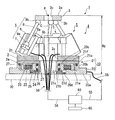
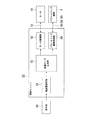
図1は、本発明の第1の実施形態に係るパラレルリンクステージの外観を示す模式的な斜視図である。図2は、図1のA−A断面図である。図3は、本発明の第1の実施形態に係るパラレルリンクステージの制御部の機能ブロック図である。
[First Embodiment]
A parallel link stage according to the first embodiment of the present invention will be described.
FIG. 1 is a schematic perspective view showing an appearance of a parallel link stage according to the first embodiment of the present invention. FIG. 2 is a cross-sectional view taken along the line AA of FIG. FIG. 3 is a functional block diagram of the control unit of the parallel link stage according to the first embodiment of the present invention.
本実施形態のパラレルリンクステージ1は、例えば、被測定体やワークなどの被保持体を高精度に位置調整および姿勢調整して保持することができるステージである。パラレルリンクステージ1は、ステージ単体として用いることもできるが、例えば、図示しない測定装置や組立装置などに組み込んで用いることができる。
以下では簡単のため、パラレルリンクステージ1は、孔あきベース70で構成される水平面上に取り付けられ、パラレルリンクステージ1の上側に被保持体を保持し、一定の基準水平面を保持の中立位置として、被保持体の位置、姿勢を変化させる場合の例で説明する。ただし、パラレルリンクステージ1は、用途に応じて、これとは異なる向き、例えば、横向き、下向きなどの任意の向きに配置することができる。
パラレルリンクステージ1の概略構成は、図1、2に示すように、モータ10(回転アクチュエータ部)、回転台部2、可動部材3、パラレルリンク機構4、および制御ユニット50(制御部)を備えている。
The
In the following, for the sake of simplicity, the
As shown in FIGS. 1 and 2, the schematic configuration of the
モータ10は、パラレルリンクステージ1を高さ方向の位置決めして設置面に固定する固定面20aを有する固定部20と、固定部20に対向して配置され、固定面20aに直交する回転軸線Cを中心として回転可能に保持された回転部21とを備え、固定部20に対する回転部21の回転軸線C回りの回転位置の位置決めを行う扁平な位置決めモータである。本実施形態では、DD(ダイレクトドライブ)モータを採用している。
The
固定部20の形状は、図1に示すように、固定面20a側が平面視略矩形状の板状とされ、図2に示すように、この上面側(固定面20aと反対側)に同心円状の内周円筒部20cおよび外周円筒部20bが立設され、内周円筒部20cの内周側に軸方向に貫通する孔部が形成されている。また、固定面20aには、後述するスケール24およびエンコーダ25を収容するため、内周円筒部20cと同軸で内周円筒部20cの外形よりも大径で下側に開口する穴部20dが設けられている。
固定面20aの上側に形成された、内周円筒部20cと外周円筒部20bとの間の溝部には、内周円筒部20cの外周面を基端として径方向に延ばされた複数のステータコイル22が設けられている。
また、穴部20dの径方向の内壁部には、スケール24から回転位置の絶対位置情報を取得するエンコーダ25が設けられている。エンコーダ25としては、例えば、光学式のロータリエンコーダを採用することができる。
As shown in FIG. 1, the
A plurality of stators, which are formed on the upper side of the
In addition, an
回転部21の形状は、上面側(固定部20との対向方向反対側)に平面視ドーナツ状の平面からなる取付面21fが形成された円環板21aと、この円環板の内縁部に下方側(固定部20側)に立設され、内周側に軸方向に貫通する円筒内周面21cが形成された円筒軸部21bと、円筒軸部21bを取り囲む外周側に円環板21aから円筒軸部21bと同方向に同軸に立設された外周円筒部21eとを備える。
円筒軸部21bは、固定部20の内周円筒部20cの内径よりもわずかに小径の外径を有し、内周円筒部20cの内周部に外輪が装着された2つの軸受27の内輪に挿入され、固定部20に対して回転軸線C回りに回転可能に取り付けられている。
また、外周円筒部21eは、外周円筒部20bの内径よりもわずかに小径の外径を有し、外周円筒部20bの内周面に外輪が挿入された軸受27の内輪に挿入され、固定部20に対して回転軸線C回りに回転可能に取り付けられている。
The shape of the rotating
The
The outer
このような取付状態で、回転部21の取付面21fは、固定部20の固定面20aに対して平行状態を保って、回転軸線C回りに回転することができるようになっている。
また、このような取り付け状態で、円筒軸部21bの先端部は穴部20d内に突出されている。この円筒軸部21bの先端部の外周には、エンコーダ25によって回転位置情報を検出するため、エンコーダパルスを発生させる形状パターンが形成された円板状のスケール24が外嵌されている。
また、外周円筒部21eの内周面には、ステータコイル22の先端とわずかな隙間を隔てて対向するように磁石23が設けられている。
また、固定部20の穴部20dの開口部には、円筒軸部21bの内径と略同径の内径、好ましくは円筒軸部21bの内径よりもわずかに大きい内径を有する円環板からなる蓋部材26が内嵌されている。これにより、穴部20d内のエンコーダ25およびスケール24と、円筒軸部21bの先端面とが、固定面20a側から覆われている。
このような構成により、円筒内周面21cおよび蓋部材26の内周面は、回転軸線Cを含む領域に回転軸線Cに沿う方向に貫通する中空孔部を構成している。
In such an attachment state, the
Further, in such an attached state, the tip end portion of the
A
The opening of the
With such a configuration, the cylindrical inner
モータ10のステータコイル22およびエンコーダ25は、動力線、信号線などを含むケーブル55を介して、制御ユニット50と電気的に接続されている。これにより、モータ10は、制御ユニット50からステータコイル22およびエンコーダ25に電力供給を受けるとともに回転位置制御のための制御信号を受信し、回転位置情報を表すエンコーダ出力信号を制御ユニット50に送信できるようになっている。
The
回転台部2は、図2に示すように、中心部に貫通孔2cを有し、モータ10の回転部21の外径を略同じ外径を有するドーナツ状の孔あき円板部材である。
回転台部2は、貫通孔2cの中心が回転軸線Cと略同軸となるように、モータ10の回転部21の取付面21f上に下面2aが重ねて配置され、不図示のねじ等によって、回転部21に固定されている。
このため、回転台部2は、モータ10によって、1つの回転軸線C回りに回転可能に支持されている。また、モータ10は、回転台部2を回転軸線C回りに回転させる回転アクチュエータ部を構成している。
また、回転台部2の貫通孔2cは、回転軸線Cを含む領域に回転軸線Cに沿う方向に貫通する中空孔部を構成している。
As shown in FIG. 2, the
The
For this reason, the
Further, the through
可動部材3は、被保持体を保持するための部材であり、本実施形態では、中心に貫通孔3cを有し、全体として、回転台部2の外形よりも小さい外径を有するドーナツ状の孔あき円板状の部材からなる。
可動部材3の図示上側は、被保持体を保持する平面であるステージ面3aとされ、ステージ面3aの裏面側(下側)のリンク連結面3bは、特に図示しないが、回転台部2の上面2b上に設けられたパラレルリンク機構4を取り付ける適宜形状が設けられている。
このため、可動部材3は、パラレルリンク機構4によって回転台部2と間隔をあけた状態で、回転台部2の上方に支持されている。
貫通孔3cの大きさや形状は、被保持体をステージ面3a上に保持できる大きさや形状であれば、適宜の大きさに設定することができる。本実施形態の貫通孔3cは、ステージ面3aに直交する高精度の円筒面によって形成され、貫通孔3cの内周面や開口形状を可動部材3の位置検出や位置出しの基準としても用いることができるようになっている。
The
The upper side of the
For this reason, the
The size and shape of the through-
パラレルリンク機構4は、回転台部2および可動部材3の間で回転軸線Cを取り囲むように周方向に間隔をあけて、6箇所で回転台部2よび可動部材3を連結し、各連結位置で回転台部2に対する可動部材3の各連結距離を変化させるものである。
本実施形態のパラレルリンク機構4は、同一の構成を有する6組の可動リンク5が、図1に示すように、回転台部2の上面2bの外周側位置、および可動部材3のリンク連結面3bの外周側位置に、それぞれ連結されている。
可動部材3における可動リンク5の連結位置は、貫通孔3cの中心に中心が一致する円周上で2つずつ周方向に等距離で近接して隣接された3組の連結位置が、円周上を3等分する位置関係に配列されている。
また、回転台部2における可動リンク5の連結位置は、回転軸線Cを中心とする円周上で2つずつ周方向に等距離で近接して隣接された3組の連結位置が、円周上を3等分する位置関係に配列されている。
ただし、回転台部2において組をなす2つずつの連結位置の間の距離は、可動部材3において組をなす2つずつの連結位置の間の距離よりも大きい設定とされている。
The parallel link mechanism 4 connects the
In the parallel link mechanism 4 of the present embodiment, as shown in FIG. 1, six sets of
The connecting positions of the
Further, the connection position of the
However, the distance between two connecting positions forming a set in the
本実施形態では、回転台部2上の6つの連結位置は、周方向に略等分された6位置となっている。このような配置とすれば、回転台部2に対する各可動リンク5の連結に要するスペースを、回転台部2上で等分することができるので、連結位置を不等間隔に設定する場合に比べて、回転台部2の外径を小径化することができる。
In the present embodiment, the six connection positions on the
各可動リンク5は、リンク部材8、および直動アクチュエータ6を備える。
リンク部材8は、一端側が、例えば、球面軸受けやユニバーサルジョイント等からなる可動側回動継手9bを介して可動部材3のリンク連結面3bに回動可能に取り付けられた一定長さの棒状部材であり、他端側は、例えば、球面軸受けやユニバーサルジョイント等らなる固定側回動継手9aを介して回動可能な状態で直動アクチュエータ6に固定されている。
可動側回動継手9bは、リンク連結面3bの外周側の連結位置で、2つ1組で近接されこれら3組が周方向に120°ピッチをなすように取り付けられている。
Each
The link member 8 is a rod-like member having a fixed length, one end of which is rotatably attached to the
The movable
直動アクチュエータ6は、固定側回動継手9aを介して回動可能に連結されたリンク部材8の他端部を、回転台部2側から可動部材3側に向かって、回転軸線Cに対する傾斜角度が、例えば0°〜45°の角度をなす斜め方向の軸線に沿って移動させる直動機構である。
本実施形態の直動アクチュエータ6は、例えば、三角ブロック状の支持ブロック6b上に斜め方向の軸線に沿って延ばして取り付けられたガイドレール6aに沿って直線移動可能に設けられたスライダ7を、例えば、ボールネジ、ナット、およびステッピングモータなどを備える不図示のボールネジ送り機構によって駆動する構成を採用している。これにより、スライダ7に回動可能に固定された固定側回動継手9aを介して、リンク部材8の他端部を直動移動させることができるようになっている。
The linear motion actuator 6 is inclined with respect to the rotation axis C from the rotary table 2 side toward the
The linear motion actuator 6 of the present embodiment includes, for example, a slider 7 provided so as to be linearly movable along a
このような構成の直動アクチュエータ6は、支持ブロック6bを介して、回転台部2上の連結位置に、位置決めされた状態でそれぞれ固定されている。
このため、各可動リンク5は、回転台部2と可動部材3との間で、回転台部2の貫通孔2c、可動部材3の貫通孔3c、および回転軸線Cを取り囲むように周方向に間隔をあけて配置されている。これにより、回転台部2と可動部材3との間には、6組の可動リンク5に囲まれる内側の中心部に開放空間が形成されている。また、この開放空間は、回転台部2および可動部材3を対向方向に貫通されている。
The linear motion actuator 6 having such a configuration is fixed in a positioned state at a connection position on the
For this reason, each
また、直動アクチュエータ6には、スライダ7の位置情報を取得するエンコーダ(不図示)が内蔵されている。
また、直動アクチュエータ6は、ケーブル56を介して制御ユニット50と電気的に接続されており、制御ユニット50から電力の供給を受けるとともに動作制御のための制御信号を受信し、スライダ7の位置情報を表すエンコーダ出力信号を制御ユニット50に送信できるようになっている。
Further, the linear actuator 6 has a built-in encoder (not shown) that acquires position information of the slider 7.
Further, the linear actuator 6 is electrically connected to the
各直動アクチュエータ6に接続されたケーブル56は、例えば、直動アクチュエータ6に三相ステッピングモータを用いる場合、4本の動力線、7本の信号線を内蔵する被覆ケーブルからなる。
各直動アクチュエータ6に接続されたケーブル56は、いずれも、回転台部2およびモータ10の中空孔部に挿通して装置外部に引き出されている。すなわち、各ケーブル56は、図2に示すように、直動アクチュエータ6から回転台部2の上面2b上を回転台部2の中心部に向かって配回され、回転台部2の貫通孔2c、およびモータ10の円筒内周面21cの内部に挿通されて、モータ10の固定面20a側からパラレルリンクステージ1の外部に導かれ、孔あきベース70の孔部を挿通されてから、制御ユニット50に接続されている。
For example, when a three-phase stepping motor is used for the linear motion actuator 6, the
Each of the
制御ユニット50は、例えば、キーボードや操作パネルなどの操作入力手段からなる操作部60を介した操作入力に応じて、パラレルリンク機構4およびモータ10の動作制御を行うことにより、モータ10の固定部20に対する可動部材3の位置制御および姿勢制御を行うもので、操作部60、パラレルリンク機構4の各可動リンク5、およびモータ10と電気的に接続されている。
制御ユニット50の機能構成は、図3に示すように、駆動量解析部51、制御データ生成部52、モータ制御部53、およびパラレルリンク機構制御部54からなる。
The
As shown in FIG. 3, the functional configuration of the
駆動量解析部51は、操作部60からの操作入力を解析して、操作入力に応じた位置、姿勢に可動部材3を配置するために、現在位置からの相対移動量を求めるものである。
例えば、固定面20aと回転軸線Cとの仮想的な交点を原点O(図2参照)として、固定面20aに沿う水平面をXY平面、このXY平面に直交する回転軸線CをZ軸とするXYZ座標系を固定座標系とする。そして、可動部材3上の1点、例えば、貫通孔3cの中心軸とステージ面3aとの仮想的な交点を原点P(図2参照)として、ステージ面3aに沿う平面をxy平面、このxy平面の原点Pを通る法線をz軸とするxyz座標系を移動座標系とする。また、移動座標系の固定座標系に対する回転を、固定座標系のX軸回り、Y軸回り、Z軸回りの回転角α、β、γを用いて表す。
ステージ面3aの位置、姿勢を、現在位置から操作入力に応じた位置、姿勢に制御するため、駆動量解析部51は、現在位置に対する移動座標系の原点Pの固定座標系における並進移動成分M(ΔX,ΔY,ΔZ)と、固定座標系に対する移動座標系の回転移動成分R(Δα,Δβ,Δγ)を算出し、制御データ生成部52へ送出できるようになっている。
The drive
For example, an imaginary intersection between the
In order to control the position and posture of the
また、操作部60からの操作入力によっては、目標の位置および姿勢に可動部材3を移動させる過程で、可動部材3の位置および姿勢を時間的に制御する必要がある場合がある。例えば、所定周期で可動部材3上の被保持体を揺動させたり、可動部材3上の被保持体を一定の姿勢を保って所定速度で回転させたりする場合がある。
このような場合、並進移動成分M(ΔX,ΔY,ΔZ)、回転移動成分R(Δα,Δβ,Δγ)は、離散的な時間の関数として算出される。
Further, depending on the operation input from the
In such a case, the translational movement component M (ΔX, ΔY, ΔZ) and the rotational movement component R (Δα, Δβ, Δγ) are calculated as discrete time functions.
制御データ生成部52は、並進移動成分M(ΔX,ΔY,ΔZ)と回転移動成分R(Δα,Δβ,Δγ)とから、可動リンク5の連結距離の変化量L(ΔL1,…,ΔL6)(以下、リンク駆動量と称する)を算出するとともに、モータ10の回転量Δφを求めるものである。
リンク駆動量Lの算出は、従来周知の6組の可動リンク5を有するパラレルリンク機構の制御データと同様にして行うことができる。
制御データ生成部52によって、算出されたリンク駆動量L(ΔL1,…,ΔL6)は、パラレルリンク機構制御部54に送出され、モータ10の回転量Δφは、モータ制御部53に送出される。
The control
The calculation of the link driving amount L can be performed in the same manner as the control data of the parallel link mechanism having the six known
The link drive amount L (ΔL 1 ,..., ΔL 6 ) calculated by the control
モータ制御部53は、制御データ生成部52から送出されたモータ10の回転量Δφの制御データに基づいて、モータ10の回転位置を変える制御を行うものであり、ケーブル55を介してモータ10に電気的に接続されている。
パラレルリンク機構制御部54は、制御データ生成部52から送出されたリンク駆動量L(ΔL1,…,ΔL6)に対応する制御データに基づいてパラレルリンク機構4の各可動リンク5の連結距離を変える制御を行うものであり、ケーブル56を介して各可動リンク5に電気的に接続されている。
The
The parallel link
このような制御ユニット50の装置構成は、ハードウェアのみで構成してもよいし、適宜のハードウェアと、CPU、メモリ、入出力インターフェース、外部記憶装置などからなるコンピュータとから構成して、上記の制御機能を、コンピュータで制御プログラムを実行することで実現してもよい。
The device configuration of the
次に、本実施形態のパラレルリンクステージ1の動作について説明する。
まず、適宜の位置出し治具や測定機などを用いて、パラレルリンクステージ1の原点出しを行う。例えば、図2に示すように、固定面20aとステージ面3aとが平行で、移動座標系の原点Pが、回転軸線C上で固定座標系の原点Oから一定距離H0となる位置に可動部材3の位置および姿勢が設定される。以下では、この状態を可動部材3の基準位置、基準姿勢と称する。
この基準位置、基準姿勢のときのモータ10のエンコーダ25の値および各可動リンク5の直動アクチュエータ6のエンコーダの値は、それぞれ、原点位置として、制御ユニット50にモータ制御部53、パラレルリンク機構制御部54に記憶される。
原点出し終了後、操作部60から可動部材3の位置、姿勢を変更する操作入力が入力されると、駆動量解析部51によって、並進移動成分M(ΔX,ΔY,ΔZ)と、回転移動成分R(Δα,Δβ,Δγ)とが算出され、制御データ生成部52に送出される。
Next, the operation of the
First, the origin of the
The value of the
When an operation input for changing the position and orientation of the
制御データ生成部52では、並進移動成分M(ΔX,ΔY,ΔZ)と回転移動成分R(Δα,Δβ,Δγ)とから、リンク駆動量L(ΔL1,…,ΔL6)およびモータ10の回転量Δφを算出し、リンク駆動量L(ΔL1,…,ΔL6)をパラレルリンクの制御データとしてパラレルリンク機構制御部54に送出し、モータ10の回転量Δφをモータの制御データとしてモータ制御部53へ送出する。
これにより、パラレルリンク機構制御部54、モータ制御部53を介して、パラレルリンク機構4の各可動リンク5の連結距離、およびモータ10の回転位置が、リンク駆動量L(ΔL1,…,ΔL6)および回転量Δφとなるように、同時並行的に制御される。
In the control
As a result, the connection distance of each
また、並進移動成分M(ΔX,ΔY,ΔZ)、回転移動成分R(Δα,Δβ,Δγ)が、離散的な時間の関数として算出される場合には、時間ステップごとに、パラレルリンク機構4の動作と、モータ10との動作とが協調制御され、パラレルリンク機構4の回転軸線C回りの回転自由度を除く5自由度の移動と、モータ10による回転軸線C回りの回転自由度の移動とが合成された6自由度の移動によって、特定の軌跡を描く移動が可能となる。
各可動リンク5に接続されたケーブル56は、貫通孔2c、円筒内周面21c等で構成される回転軸線Cを含む中空孔部に挿通されている。このため、あらかじめケーブル56の長さを適宜の長さに設けておくことで、ケーブル56が可動部材3の回転角に応じて緩やかにねじられ、回転台部2の回転の妨げとはならないようにすることができる。
このように、本実施形態では、回転台部2およびモータ10が、中空孔部を有するため、回転系と固定系とをつなぐケーブル56の配回しが容易となっている。
When the translational movement component M (ΔX, ΔY, ΔZ) and the rotational movement component R (Δα, Δβ, Δγ) are calculated as a function of discrete time, the parallel link mechanism 4 is provided for each time step. And the operation with the
The
Thus, in this embodiment, since the
可動部材3を回転軸線C回りに回転移動させるには、例えば、可動部材3上で可動側回動継手9bが近接されている各組の可動リンク5の連結距離を一方は伸ばし、他方を縮めることで、各可動側回動継手9bの回転軸線Cに対する周方向の位置をずらすことで、パラレルリンク機構4のみによって行うことも可能である。しかしながら、この場合、各可動リンク5の伸縮量の限度や隣接する可動リンク5同士の干渉を防止するための限度によって、回転移動範囲が限定されてしまう。
このため、パラレルリンク機構4のみでは、例えば、360°以上回転させることはかなり困難であり、例えば、±15°程度の回転範囲が実質的な限度である。
本実施形態では、回転軸線C回りの回転はモータ10によって行うため、各ケーブル56のねじれが許容できる範囲であれば、回転範囲には特に制限はない。4本の動力線および7本の信号線程度を内蔵するケーブル56であれば、±2〜3回転程度は容易であり、±3回転以上も十分可能である。
In order to rotate the
For this reason, for example, it is quite difficult to rotate 360 ° or more with only the parallel link mechanism 4. For example, a rotation range of about ± 15 ° is a practical limit.
In the present embodiment, since the rotation about the rotation axis C is performed by the
本実施形態のパラレルリンクステージ1におけるパラレルリンク機構4とモータ10との協調制御によって容易となる可動部材3の移動制御の一例として、固定座標系において可動部材3を基準姿勢から一定角度傾けた状態を保って、可動部材3を原点Pを中心として回転させる移動制御を挙げることができる。
このような移動制御を行うには、モータ10の回転周期に同期させた周期で、可動部材3上の各点の回転軸線Cに沿う方向の高さを正弦波状に変化させればよい。
As an example of movement control of the
In order to perform such movement control, the height in the direction along the rotation axis C of each point on the
このように、本実施形態では、制御ユニット50によって、パラレルリンク機構4およびモータ10の動作制御を行うことにより、パラレルリンク機構4の有する移動自由度、移動範囲、移動精度において可動部材3を回転台部2に対して相対移動させることができるとともに、回転台部2をモータ10の回転範囲で、回転軸線C回りに回転させることができる。
As described above, in this embodiment, the
また、本実施形態では、可動部材3には、回転モータなどを設けることなく、可動部材3を回転軸線C回りに複数回転させることができるので、回転モータなどを設ける場合に比べて、可動部材3を軽量化することができる。これによりパラレルリンク機構4の出力も低減できるため、全体として装置を小型化することができる。また、可動部材3の下面側の空間を省スペース化できるため、装置を小型化することができる。
また、可動部材3に回転増幅機を設ける場合のように、可動部材3と回転台部2との間においてパラレルリンク機構4に囲まれる領域の中心部が、回転増幅機によって占有されることなく、開放空間を形成することができる。これにより、可動部材3および回転台部2の間の装置構成を簡素化することができる。この開放空間は、可動部材3上の被保持体を下側から観察したり、可動部材3の原点出し時に貫通孔3cを観察したりするために用いることができる。また、可動部材3の原点出し時に位置決め治具などを配置する空間としても利用することができる。
Further, in the present embodiment, the
Further, as in the case where a rotary amplifier is provided on the
このように本実施形態のパラレルリンクステージ1は、モータ10によって回転台部2上に設けられたパラレルリンク機構4をパラレルリンク機構4の並列方向に沿う方向(回転軸線C回り)に回転させることができるので、パラレルリンク機構4に支持された可動部材3の、パラレルリンク機構4の並列方向に沿う回転範囲を向上することができるとともに、可動部材3およびパラレルリンク機構4によって囲まれる領域の中心部に開放空間を形成することができる。
As described above, the
[第2の実施形態]
本発明の第2の実施形態に係るパラレルリンクステージおよび光学素子測定装置について説明する。
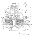
図4は、本発明の第2の実施形態に係るパラレルリンクステージおよび光学素子測定装置の模式的な断面図である。
[Second Embodiment]
A parallel link stage and an optical element measuring apparatus according to a second embodiment of the present invention will be described.
FIG. 4 is a schematic cross-sectional view of a parallel link stage and an optical element measuring apparatus according to the second embodiment of the present invention.
本実施形態のパラレルリンクステージ1Aは、図4に示すように、上記第1の実施形態のパラレルリンクステージ1に回転コネクタ12を追加したものである。
また、本実施形態の光学素子測定装置100は、パラレルリンクステージ1A、光学素子保持部17、および光学測定部16(測定部)を備えるものである。
以下、上記第1の実施形態と異なる点を中心に説明する。
As shown in FIG. 4, the
Moreover, the optical
Hereinafter, a description will be given centering on differences from the first embodiment.
回転コネクタ12は、コネクタ固定部12bおよびコネクタ回転部12aを備える全体として筒状の部材である。
コネクタ固定部12bは、円筒内周面21cの内側に挿入され、端部が蓋部材26に固定されることで、固定部20と固定された筒状部材からなる。
コネクタ固定部12bの筒内部には、筒内周側に設けられた接点(不図示)に一端が接続された複数の配線(不図示)が設けられている。これらの配線の他端側は、蓋部材26からモータ10の外側に突出されたコネクタ固定部12bの筒外周部で、固定側コネクタ部12eにそれぞれ結線されている。
The
The
A plurality of wires (not shown) whose one ends are connected to contacts (not shown) provided on the inner peripheral side of the cylinder are provided inside the
コネクタ回転部12aは、コネクタ固定部12bの内周部に挿入された状態でコネクタ回転部12aと回転可能に連結され、回転中心軸線に沿って中空孔部12dが形成された筒状部材からなる。
コネクタ回転部12aのコネクタ固定部12bに挿入されたのと反対側の端部は、モータ10の固定部20の内周円筒部20cに内嵌された状態で、固定部20に固定されている。
コネクタ回転部12aの内部には、コネクタ固定部12bの各接点と静止時および回転時にそれぞれ電気的接触を保つ複数の接点(不図示)と、これらの接点に一端が接続された複数の配線(不図示)が設けられている。これらの配線の他端側は、回転部21側の軸方向の端面において、中空孔部12dを外周側で取り囲む円周上に設けられた回転側コネクタ部12cにそれぞれ結線されている。
The
An end portion of the
Inside the
回転側コネクタ部12cには、パラレルリンク機構4の各直動アクチュエータ6に電気的に接続されたケーブル58がそれぞれ連結されている。このため、各ケーブル58は、各直動アクチュエータ6から回転側コネクタ部12cに向かって回転台部2の径方向に沿って配回されている。これにより、各ケーブル58は、中空孔部12d上を横断することなく回転台部2の上面2b上に配回されている。
また、固定側コネクタ部12eには、制御ユニット50のパラレルリンク機構制御部54(図3参照)に電気的に接続されたケーブル59が連結されている。
Further, a
このような構成により、パラレルリンクステージ1Aでは、各直動アクチュエータ6は、回転部21の静止時および回転時のいずれでも、ケーブル58、回転コネクタ12、およびケーブル59を介して、パラレルリンク機構制御部54と電気的に接続されている。
また、回転コネクタ12の中空孔部12dは、回転軸線Cを含む領域に回転軸線Cに沿う方向に貫通されている。
With such a configuration, in the
Further, the
光学素子保持部17は、光学素子測定装置100の被測定体として、例えば、レンズ、平行平板、プリズム、およびミラーなどからなる光学素子Wの外周部を位置決めして保持する保持部17aと、保持部17aに保持された光学素子Wの内周部に対向する開口を形成する貫通孔17bとを備える全体として円筒状または円環状の部材である。
光学素子保持部17は、保持部17aに平行な固定面17cを可動部材3のステージ面3aに当接させた状態で、貫通孔17bが、貫通孔3c上に位置するように位置決めして固定されている。本実施形態では、貫通孔17bは、光学素子Wの有効径よりも大きい内径を有し、貫通孔3cは、貫通孔17bよりも大きい内径を有している。これにより、可動部材3の下方側から、光学素子Wの有効領域全体を観察することが可能となっている。
The optical
The optical
光学測定部16は、パラレルリンクステージ1の下方(モータ10側)から中空孔部12dに対向する位置に配置され、中空孔部12dおよび可動部材3の貫通孔3cを通して光学素子保持部17上に保持された光学素子Wの測定を行うものである。
光学測定部16は、中空孔部12dおよび貫通孔3cを通して、光学素子Wを測定できるものであれば、適宜の測定機を採用することができる。光学測定部16に好適な測定機としては、例えば、MTF測定機、干渉計、偏心測定機、反射率測定機等の測定機を挙げることができる。これらの測定機では、中空孔部12dおよび貫通孔3cの間の中心部に形成された開放空間を通して、測定光の送受光を行えるため、光学素子Wを測定することができる。
本実施形態では、光学測定部16の配置位置は、光学測定部16の測定基準軸が回転軸線Cと同軸となるように設定されている。
The
As long as the optical measuring
In the present embodiment, the arrangement position of the
次に、本実施形態の光学素子測定装置100の動作について、パラレルリンクステージ1Aの動作を中心に説明する。
光学素子測定装置100では、光学素子保持部17に光学素子Wを保持させ、パラレルリンクステージ1Aを用いて、光学素子Wの測定を開始するための位置および姿勢に移動させる。パラレルリンクステージ1Aの動作制御は、上記第1の実施形態のパラレルリンクステージ1と同様である。
例えば、光学素子Wがレンズ等の場合に、光学測定部16により中空孔部12d、貫通孔3c、および貫通孔17bを通して光学素子Wの表面を観察しながら、パラレルリンクステージ1Aによって可動部材3を移動させる。これにより、光学素子Wの光軸を光学測定部16の測定基準軸に一致させたり、測定基準軸に対して、一定距離偏心させたり、光学測定部16との間の測定基準軸上の距離を調整したり、といった位置、姿勢の調整を行う。
このようにして、測定開始位置に光学素子Wが配置されたら、光学測定部16によって光学素子Wの測定を行う。
その際、パラレルリンクステージ1Aによって、例えば測定部位を変更するといった必要に応じて、可動部材3の位置、姿勢を変更させつつ測定を行うことができる。
パラレルリンクステージ1Aは、モータ10を備えており、回転軸線C回りの回転範囲が大きくなっているため、光学素子Wを光軸回りに何回転かさせて測定を行うことが可能となる。
また、モータ10とパラレルリンク機構4との移動量を協調制御することで、光学素子Wの光軸を固定座標系に対して一定に保った状態で、光学素子Wを回転軸線C回りに回転させる、といった制御が可能となる。
Next, the operation of the optical
In the optical
For example, when the optical element W is a lens or the like, the
In this way, when the optical element W is arranged at the measurement start position, the optical element W is measured by the
At that time, the
Since the
Further, by cooperatively controlling the movement amount of the
また、パラレルリンクステージ1Aは、回転コネクタ12を備えているため、モータ10が回転しても、回転側コネクタ部12cに接続されたケーブル58と、固定側コネクタ部12eに接続されたケーブル59との間の相対回転は、回転コネクタ12の回転によって吸収される。
このため、各ケーブル58は、モータ10の回転とともに回転台部2上での相対位置を保ったまま回転され、ケーブル59はモータ10が回転しても回転されることはない。これにより、モータ10が回転されてもパラレルリンクステージ1のようなケーブルのねじれがまったく発生しないため、モータ10の回転範囲には制限がない。
したがって、パラレルリンクステージ1Aによれば、光学素子Wを回転軸線C回りの連続回転を所望回数行って、光学測定部16による測定を行うことができる。
Further, since the
For this reason, each
Therefore, according to the
なお、上記の第1の実施形態の説明では、パラレルリンクステージ1の可動部材3に貫通孔3cが設けられ、回転台部2の貫通孔2c、モータ10の円筒内周面21cで形成される中空孔部によって、回転軸線Cに沿って連通する開放空間が形成される場合の例で説明したが、可動部材3上の被保持体を下方から観察したり、測定したりする必要がない場合には、貫通孔3cを有しない構成としてもよい。
In the description of the first embodiment, the
また、上記の第2の実施形態の説明では、光学素子測定装置100として、パラレルリンクステージ1Aを備える場合の例で説明したが、光学測定部16による測定に支障がないようにケーブル56を挿通させることができれば、パラレルリンクステージ1Aに代えてパラレルリンクステージ1を採用してもよい。例えば、ケーブル56を円筒内周面21cに近い領域に配置して、円筒内周面21cの中心部に開放空間を形成すればよい。
In the description of the second embodiment, the example in which the
また、上記の説明では、回転軸線回りの回転移動は、すべて回転アクチュエータ部によって行う場合の例で説明したが、回転軸線回りの回転移動量を回転アクチュエータ部とパラレルリンク機構との間で適宜に分割してもよい。
例えば、一定の回転量よりも少ない回転や、回転アクチュエータの回転分解能以下の回転をパラレルリンク機構が行うようにしてもよい。
In the above description, the rotational movement around the rotation axis is described as an example in which all rotation movement is performed by the rotation actuator. However, the amount of rotation movement around the rotation axis is appropriately determined between the rotation actuator and the parallel link mechanism. It may be divided.
For example, the parallel link mechanism may perform rotation less than a certain rotation amount or rotation less than the rotation resolution of the rotary actuator.
また、上記の説明では、回転アクチュエータ部を扁平なDDモータで構成した例で説明したが、回転アクチュエータ部は、例えば、回転可能に支持された回転台部に、例えば歯車機構やベルト伝動機構などの伝動機構を介して回転力を伝動させるモータなどから構成してもよい。 Further, in the above description, the example in which the rotation actuator unit is configured by a flat DD motor has been described. However, the rotation actuator unit is, for example, a gear mechanism, a belt transmission mechanism, etc. You may comprise from the motor etc. which transmit a rotational force through this transmission mechanism.
また、上記の説明では、モータ10の回転部21に、回転台部2が固定された構成の例で説明したが、モータ10の回転部21に、直接、可動リンク5を連結し、回転部21が回転台部を構成するようにしてもよい。
In the above description, the example of the configuration in which the
また、上記の説明では、パラレルリンク機構4としては、固定長のリンク部材8を、直動アクチュエータ6とによって移動させることで、回転台部2と可動部材3との間の連結距離を変える構成の例で説明したが、パラレルリンク機構は、長さが伸縮可能に設けられた6組の可変長リンクによって、回転台部2と可動部材3との間の連結距離を変える構成としてもよい。
In the above description, the parallel link mechanism 4 is configured to change the connection distance between the
また、上記の説明では、パラレルリンク機構4が6組の可動リンク5を有する場合の例で説明したが、可動リンク5は少なくとも3組あればよい。この場合でも、回転軸線C回りの回転移動をモータ10によって行うことができるので、上記と同様に位置、姿勢制御を行うことができる。
In the above description, an example in which the parallel link mechanism 4 has six sets of
また、上記第2の実施形態の説明では、回転コネクタ12の回転軸線と、回転軸線Cとが同軸である場合の例で説明したが、回転コネクタ12の回転軸線と回転軸線Cとは、略同軸であればよい。その際、回転コネクタ12のコネクタ回転部12aが回転台部2、もしくはモータ10の回転部21に固定され、回転コネクタ12のコネクタ固定部12bはモータ10の固定部20、もしくはモータ10を固定している孔あきベース70等の他の構造物に固定してもよい。
In the description of the second embodiment, the example in which the rotation axis of the
また、上記第2の実施形態の説明では、回転コネクタ12が回転側コネクタ部12cを有する場合の例で説明したが、回転側コネクタ部12cを半田付け端子に置き換え、ケーブル58の配線を半田付け端子に半田付け接合した構成としてもよい。
また、固定側コネクタ部12eも同様である。
また、ケーブル56は複数線の被覆ケーブルとせず、動力線、信号線等をそれぞれ独立した細径ケーブルに分けてもよい。また、これらの細径ケーブルと緩やかに結束したケーブル束としてもよい。
In the description of the second embodiment, the example in which the
The same applies to the fixed-
The
また、上記の各実施形態に説明したすべての構成要素は、本発明の技術的思想の範囲で適宜組み合わせて実施することができる。 In addition, all the components described in the above embodiments can be implemented in appropriate combination within the scope of the technical idea of the present invention.
1、1A パラレルリンクステージ
2c 貫通孔
3 可動部材
3c 貫通孔
4 パラレルリンク機構
5 可動リンク
6 直動アクチュエータ
8 リンク部材
10 モータ(回転アクチュエータ部)
12 回転コネクタ
12d 中空孔部
16 光学測定部
17 光学素子保持部
17b 貫通孔
21c 円筒内周面(中空孔部)
25 エンコーダ
50 制御ユニット
51 駆動量解析部
52 制御データ生成部
53 モータ制御部
54 パラレルリンク機構制御部
55、56、58、59 ケーブル
60 操作部
100 光学素子測定装置
C 回転軸線
W 光学素子
DESCRIPTION OF
12
25
Claims (5)
該回転台部を前記回転軸線回りに回転させる回転アクチュエータ部と、
前記回転台部に対して間隔をあけて配置される可動部材と、
前記回転台部および前記可動部材の間で前記回転軸線を取り囲むように周方向に間隔をあけて、少なくとも3箇所で前記回転台部および前記可動部材を連結し、各連結位置で前記回転台部に対する前記可動部材の各連結距離を変化させるパラレルリンク機構と、
該パラレルリンク機構および前記回転アクチュエータ部の動作制御を行うことにより、前記可動部材の位置制御および姿勢制御を行う制御部と、を備えることを特徴とするパラレルリンクステージ。 A turntable unit rotatably supported around the rotation axis;
A rotation actuator for rotating the turntable about the rotation axis;
A movable member disposed at an interval with respect to the turntable unit;
The rotary base and the movable member are connected to each other at at least three positions with a circumferential interval between the rotary base and the movable member so as to surround the rotation axis. A parallel link mechanism for changing each connecting distance of the movable member with respect to
A parallel link stage comprising: a control unit that performs position control and posture control of the movable member by performing operation control of the parallel link mechanism and the rotary actuator unit.
前記回転台部および前記回転アクチュエータ部のそれぞれの前記回転軸線を含む領域には、前記回転軸線に沿う方向に貫通する中空孔部が設けられたことを特徴とするパラレルリンクステージ。 The parallel link stage according to claim 1,
The parallel link stage characterized by the hollow hole part which penetrates in the direction in alignment with the said rotation axis in the area | region containing the said rotation axis of each of the said rotation base part and the said rotation actuator part.
前記回転台部および前記回転アクチュエータ部にまたがって前記回転軸線と同軸となるように取り付けられ、前記回転アクチュエータの静止時および回転時に前記パラレルリンク機構と前記制御部とを電気的に接続する回転コネクタを備え、
該回転コネクタの前記前記回転軸線を含む領域には、前記回転軸線に沿う方向に貫通する中空孔部が設けられたことを特徴とするパラレルリンクステージ。 The parallel link stage according to claim 1,
A rotary connector that is attached to the rotary base and the rotary actuator so as to be coaxial with the rotary axis, and electrically connects the parallel link mechanism and the controller when the rotary actuator is stationary and rotating. With
A parallel link stage characterized in that a hollow hole portion penetrating in a direction along the rotation axis is provided in a region including the rotation axis of the rotary connector.
前記可動部材は、前記中空孔部に対向する位置に、厚さ方向に貫通する貫通孔を備えたことを特徴とするパラレルリンクステージ。 The parallel link stage according to claim 2 or 3,
The parallel link stage, wherein the movable member includes a through-hole penetrating in a thickness direction at a position facing the hollow hole portion.
前記可動部材上に設けられ、該可動部材の前記貫通孔上に光学素子を保持する光学素子保持部と、
前記回転アクチュエータ部側から前記中空孔部に対向する位置に配置され、該中空孔部および前記可動部材の前記貫通孔を通して前記光学素子の測定を行う測定部と、を備えたことを特徴とする光学素子測定装置。 The parallel link stage according to claim 4,
An optical element holding unit provided on the movable member and holding an optical element on the through hole of the movable member;
A measuring unit that is disposed at a position facing the hollow hole part from the rotary actuator part side, and that measures the optical element through the hollow hole part and the through-hole of the movable member. Optical element measuring device.
Priority Applications (1)
| Application Number | Priority Date | Filing Date | Title |
|---|---|---|---|
| JP2009095914A JP2010247238A (en) | 2009-04-10 | 2009-04-10 | Parallel link stage and optical element measuring instrument |
Applications Claiming Priority (1)
| Application Number | Priority Date | Filing Date | Title |
|---|---|---|---|
| JP2009095914A JP2010247238A (en) | 2009-04-10 | 2009-04-10 | Parallel link stage and optical element measuring instrument |
Publications (1)
| Publication Number | Publication Date |
|---|---|
| JP2010247238A true JP2010247238A (en) | 2010-11-04 |
Family
ID=43310181
Family Applications (1)
| Application Number | Title | Priority Date | Filing Date |
|---|---|---|---|
| JP2009095914A Withdrawn JP2010247238A (en) | 2009-04-10 | 2009-04-10 | Parallel link stage and optical element measuring instrument |
Country Status (1)
| Country | Link |
|---|---|
| JP (1) | JP2010247238A (en) |
Cited By (8)
| Publication number | Priority date | Publication date | Assignee | Title |
|---|---|---|---|---|
| JP2013107174A (en) * | 2011-11-22 | 2013-06-06 | Rhombic Corp | Suction device |
| JP2014050898A (en) * | 2012-09-05 | 2014-03-20 | Fanuc Ltd | Wire body processing structure of parallel link robot |
| JP2014237187A (en) * | 2013-06-07 | 2014-12-18 | 株式会社安川電機 | Parallel link robot, robot system, and construction method of conveyance facility |
| JP2015188945A (en) * | 2014-03-27 | 2015-11-02 | Ntn株式会社 | Coating device |
| WO2019097814A1 (en) * | 2017-11-20 | 2019-05-23 | ソニー株式会社 | Extending and retracting mechanism |
| WO2021182024A1 (en) * | 2020-03-09 | 2021-09-16 | 株式会社 東芝 | Robot system, parallel link mechanism, control method, control device, program, and storage medium |
| CN114619264A (en) * | 2022-05-10 | 2022-06-14 | 浙江科技学院 | Multi-angle rotary type casting machining device |
| CN117620778A (en) * | 2023-12-29 | 2024-03-01 | 北京星航机电装备有限公司 | A method for aligning the surface to be processed and a fixing tool |
-
2009
- 2009-04-10 JP JP2009095914A patent/JP2010247238A/en not_active Withdrawn
Cited By (17)
| Publication number | Priority date | Publication date | Assignee | Title |
|---|---|---|---|---|
| JP2013107174A (en) * | 2011-11-22 | 2013-06-06 | Rhombic Corp | Suction device |
| JP2014050898A (en) * | 2012-09-05 | 2014-03-20 | Fanuc Ltd | Wire body processing structure of parallel link robot |
| CN103659801A (en) * | 2012-09-05 | 2014-03-26 | 发那科株式会社 | Umbilical member processing structure of parallel link robot |
| CN103659801B (en) * | 2012-09-05 | 2016-11-23 | 发那科株式会社 | The filament of parallel link manipulator processes structure |
| US9694493B2 (en) | 2012-09-05 | 2017-07-04 | Fanuc Corporation | Umbilical member arrangement structure of parallel link robot |
| JP2014237187A (en) * | 2013-06-07 | 2014-12-18 | 株式会社安川電機 | Parallel link robot, robot system, and construction method of conveyance facility |
| US9649771B2 (en) | 2013-06-07 | 2017-05-16 | Kabushiki Kaisha Yaskawa Denki | Parallel robot, robot system, and assembly method for transfer system |
| JP2015188945A (en) * | 2014-03-27 | 2015-11-02 | Ntn株式会社 | Coating device |
| WO2019097814A1 (en) * | 2017-11-20 | 2019-05-23 | ソニー株式会社 | Extending and retracting mechanism |
| WO2021182024A1 (en) * | 2020-03-09 | 2021-09-16 | 株式会社 東芝 | Robot system, parallel link mechanism, control method, control device, program, and storage medium |
| JP2021137939A (en) * | 2020-03-09 | 2021-09-16 | 株式会社東芝 | Robot system, parallel link mechanism, control method, control device, program and memory medium |
| CN115279555A (en) * | 2020-03-09 | 2022-11-01 | 株式会社东芝 | Robot system, parallel link mechanism, control method, control device, program, and storage medium |
| JP7462437B2 (en) | 2020-03-09 | 2024-04-05 | 株式会社東芝 | ROBOT SYSTEM, PARALLEL LINK MECHANISM, CONTROL METHOD, CONTROL DEVICE, PROGRAM, AND STORAGE MEDIUM |
| US12330308B2 (en) | 2020-03-09 | 2025-06-17 | Kabushiki Kaisha Toshiba | Robot system, parallel link mechanism, control method, control device, and storage medium |
| CN114619264A (en) * | 2022-05-10 | 2022-06-14 | 浙江科技学院 | Multi-angle rotary type casting machining device |
| CN114619264B (en) * | 2022-05-10 | 2022-12-20 | 浙江科技学院 | Multi-angle rotary type casting machining device |
| CN117620778A (en) * | 2023-12-29 | 2024-03-01 | 北京星航机电装备有限公司 | A method for aligning the surface to be processed and a fixing tool |
Similar Documents
| Publication | Publication Date | Title |
|---|---|---|
| JP2010247238A (en) | Parallel link stage and optical element measuring instrument | |
| US7975568B2 (en) | Robotic arm driving mechanism | |
| JP4659098B2 (en) | Parallel link robot with posture change mechanism with 3 degrees of freedom | |
| US20190293402A1 (en) | Arm type coordinate measuring machine | |
| JP2008275624A (en) | Coordinate measuring method and device | |
| US20100043577A1 (en) | Robotic manipulator | |
| JP2011112414A (en) | Force sensor testing device | |
| WO2018184256A1 (en) | Single point laser vibration measurer based multi-directional wide-angle and continuous-scan vibration measurement auxiliary instrument | |
| CN114770605B (en) | Robot measurement and calibration system | |
| JP5250286B2 (en) | Tracking laser interferometer | |
| JP2017177276A (en) | robot | |
| JP3604686B1 (en) | 4-axis XYθ table and control method thereof | |
| JP5394358B2 (en) | Parallel link robot with posture change mechanism with 3 degrees of freedom | |
| CN103386680A (en) | Parallel two-degree of freedom orienting device | |
| JP2025043977A (en) | Driving device, controlling method, robot, program, recording medium, and method of manufacturing article | |
| JP5325551B2 (en) | Gonio stage equipment | |
| EP0997239A2 (en) | Structure of cable and/or pipe arrangement applied in parallel link mechanism | |
| JP6513045B2 (en) | Turning mechanism and positioning device | |
| US4874286A (en) | Manipulator with rod mechanism | |
| JP2021085755A (en) | Detection device, drive unit, robotic device, detection method, method of manufacturing articles using robotic device, control program, and recording medium | |
| JP7374737B2 (en) | Detection device, drive device, control method for drive device, robot device, control method for robot device, detection method, method for manufacturing articles using robot device, program, and recording medium | |
| CN112809409B (en) | A six-axis linkage auxiliary processing platform and control method thereof | |
| JP2000291761A (en) | Multi-DOF mechanism | |
| CN119238141A (en) | A joint type universal turntable and multi-axis machine tool | |
| CN222761595U (en) | Position measuring device |
Legal Events
| Date | Code | Title | Description |
|---|---|---|---|
| A300 | Withdrawal of application because of no request for examination |
Free format text: JAPANESE INTERMEDIATE CODE: A300 Effective date: 20120703 |