JP7462437B2 - ROBOT SYSTEM, PARALLEL LINK MECHANISM, CONTROL METHOD, CONTROL DEVICE, PROGRAM, AND STORAGE MEDIUM - Google Patents
ROBOT SYSTEM, PARALLEL LINK MECHANISM, CONTROL METHOD, CONTROL DEVICE, PROGRAM, AND STORAGE MEDIUM Download PDFInfo
- Publication number
- JP7462437B2 JP7462437B2 JP2020040214A JP2020040214A JP7462437B2 JP 7462437 B2 JP7462437 B2 JP 7462437B2 JP 2020040214 A JP2020040214 A JP 2020040214A JP 2020040214 A JP2020040214 A JP 2020040214A JP 7462437 B2 JP7462437 B2 JP 7462437B2
- Authority
- JP
- Japan
- Prior art keywords
- attitude
- arm mechanism
- control point
- control device
- parallel link
- Prior art date
- Legal status (The legal status is an assumption and is not a legal conclusion. Google has not performed a legal analysis and makes no representation as to the accuracy of the status listed.)
- Active
Links
Images




Classifications
-
- B—PERFORMING OPERATIONS; TRANSPORTING
- B25—HAND TOOLS; PORTABLE POWER-DRIVEN TOOLS; MANIPULATORS
- B25J—MANIPULATORS; CHAMBERS PROVIDED WITH MANIPULATION DEVICES
- B25J9/00—Program-controlled manipulators
- B25J9/16—Program controls
- B25J9/1656—Program controls characterised by programming, planning systems for manipulators
- B25J9/1664—Program controls characterised by programming, planning systems for manipulators characterised by motion, path, trajectory planning
-
- B—PERFORMING OPERATIONS; TRANSPORTING
- B25—HAND TOOLS; PORTABLE POWER-DRIVEN TOOLS; MANIPULATORS
- B25J—MANIPULATORS; CHAMBERS PROVIDED WITH MANIPULATION DEVICES
- B25J9/00—Program-controlled manipulators
- B25J9/003—Program-controlled manipulators having parallel kinematics
- B25J9/0045—Program-controlled manipulators having parallel kinematics with kinematics chains having a rotary joint at the base
- B25J9/0051—Program-controlled manipulators having parallel kinematics with kinematics chains having a rotary joint at the base with kinematics chains of the type rotary-universal-universal or rotary-spherical-spherical, e.g. Delta type manipulators
-
- B—PERFORMING OPERATIONS; TRANSPORTING
- B23—MACHINE TOOLS; METAL-WORKING NOT OTHERWISE PROVIDED FOR
- B23K—SOLDERING OR UNSOLDERING; WELDING; CLADDING OR PLATING BY SOLDERING OR WELDING; CUTTING BY APPLYING HEAT LOCALLY, e.g. FLAME CUTTING; WORKING BY LASER BEAM
- B23K31/00—Processes relevant to this subclass, specially adapted for particular articles or purposes, but not covered by any single one of main groups B23K1/00 - B23K28/00
- B23K31/12—Processes relevant to this subclass, specially adapted for particular articles or purposes, but not covered by any single one of main groups B23K1/00 - B23K28/00 relating to investigating the properties, e.g. the weldability, of materials
- B23K31/125—Weld quality monitoring
-
- B—PERFORMING OPERATIONS; TRANSPORTING
- B25—HAND TOOLS; PORTABLE POWER-DRIVEN TOOLS; MANIPULATORS
- B25J—MANIPULATORS; CHAMBERS PROVIDED WITH MANIPULATION DEVICES
- B25J17/00—Joints
- B25J17/02—Wrist joints
- B25J17/0208—Compliance devices
- B25J17/0216—Compliance devices comprising a stewart mechanism
-
- B—PERFORMING OPERATIONS; TRANSPORTING
- B25—HAND TOOLS; PORTABLE POWER-DRIVEN TOOLS; MANIPULATORS
- B25J—MANIPULATORS; CHAMBERS PROVIDED WITH MANIPULATION DEVICES
- B25J17/00—Joints
- B25J17/02—Wrist joints
- B25J17/0258—Two-dimensional joints
- B25J17/0266—Two-dimensional joints comprising more than two actuating or connecting rods
-
- B—PERFORMING OPERATIONS; TRANSPORTING
- B25—HAND TOOLS; PORTABLE POWER-DRIVEN TOOLS; MANIPULATORS
- B25J—MANIPULATORS; CHAMBERS PROVIDED WITH MANIPULATION DEVICES
- B25J9/00—Program-controlled manipulators
- B25J9/16—Program controls
- B25J9/1615—Program controls characterised by special kind of manipulator, e.g. planar, scara, gantry, cantilever, space, closed chain, passive/active joints and tendon driven manipulators
- B25J9/1623—Parallel manipulator, Stewart platform, links are attached to a common base and to a common platform, plate which is moved parallel to the base
-
- B—PERFORMING OPERATIONS; TRANSPORTING
- B25—HAND TOOLS; PORTABLE POWER-DRIVEN TOOLS; MANIPULATORS
- B25J—MANIPULATORS; CHAMBERS PROVIDED WITH MANIPULATION DEVICES
- B25J9/00—Program-controlled manipulators
- B25J9/16—Program controls
- B25J9/1628—Program controls characterised by the control loop
- B25J9/1653—Program controls characterised by the control loop parameters identification, estimation, stiffness, accuracy, error analysis
-
- B—PERFORMING OPERATIONS; TRANSPORTING
- B25—HAND TOOLS; PORTABLE POWER-DRIVEN TOOLS; MANIPULATORS
- B25J—MANIPULATORS; CHAMBERS PROVIDED WITH MANIPULATION DEVICES
- B25J9/00—Program-controlled manipulators
- B25J9/16—Program controls
- B25J9/1694—Program controls characterised by use of sensors other than normal servo-feedback from position, speed or acceleration sensors, perception control, multi-sensor controlled systems, sensor fusion
- B25J9/1697—Vision controlled systems
-
- G—PHYSICS
- G05—CONTROLLING; REGULATING
- G05B—CONTROL OR REGULATING SYSTEMS IN GENERAL; FUNCTIONAL ELEMENTS OF SUCH SYSTEMS; MONITORING OR TESTING ARRANGEMENTS FOR SUCH SYSTEMS OR ELEMENTS
- G05B2219/00—Program-control systems
- G05B2219/30—Nc systems
- G05B2219/39—Robotics, robotics to robotics hand
- G05B2219/39391—Visual servoing, track end effector with camera image feedback
-
- G—PHYSICS
- G05—CONTROLLING; REGULATING
- G05B—CONTROL OR REGULATING SYSTEMS IN GENERAL; FUNCTIONAL ELEMENTS OF SUCH SYSTEMS; MONITORING OR TESTING ARRANGEMENTS FOR SUCH SYSTEMS OR ELEMENTS
- G05B2219/00—Program-control systems
- G05B2219/30—Nc systems
- G05B2219/39—Robotics, robotics to robotics hand
- G05B2219/39552—Stewart platform hand, parallel structured hand
-
- G—PHYSICS
- G05—CONTROLLING; REGULATING
- G05B—CONTROL OR REGULATING SYSTEMS IN GENERAL; FUNCTIONAL ELEMENTS OF SUCH SYSTEMS; MONITORING OR TESTING ARRANGEMENTS FOR SUCH SYSTEMS OR ELEMENTS
- G05B2219/00—Program-control systems
- G05B2219/30—Nc systems
- G05B2219/40—Robotics, robotics mapping to robotics vision
- G05B2219/40524—Replace link, joint, structure by stewart platform to model flexibility
Landscapes
- Engineering & Computer Science (AREA)
- Mechanical Engineering (AREA)
- Robotics (AREA)
- Quality & Reliability (AREA)
- Health & Medical Sciences (AREA)
- General Health & Medical Sciences (AREA)
- Orthopedic Medicine & Surgery (AREA)
- Manipulator (AREA)
Description
本発明の実施形態は、ロボットシステム、パラレルリンク機構、制御方法、制御装置、プログラム、及び記憶媒体に関する。 Embodiments of the present invention relate to a robot system, a parallel link mechanism, a control method, a control device, a program, and a storage medium.
多関節のアーム機構は、産業に広く利用されている。例えば、アーム機構に取り付けられたエンドエフェクタを用いて作業が実行される際、フィードバック制御により、制御点の姿勢を調整する場合がある。調整中、制御点の姿勢が特異点近傍になると、アーム機構の動作が不安定となる。この結果、アーム機構又はエンドエフェクタが別の部材と干渉したり、作業に通常よりも長い時間を要したりする可能性がある。 Articulated arm mechanisms are widely used in industry. For example, when a task is performed using an end effector attached to an arm mechanism, the attitude of the control point may be adjusted by feedback control. If the attitude of the control point becomes close to a singular point during adjustment, the operation of the arm mechanism becomes unstable. As a result, the arm mechanism or end effector may interfere with other components, or the task may take longer than usual.
本発明の一実施形態は、フィードバック制御により制御点の姿勢を調整する場合において、不安定な動作の発生を抑制できる、ロボットシステム、制御方法、制御装置、プログラム、及び記憶媒体を提供する。
本発明の別の一実施形態は、ロボットシステムに好適に用いられるパラレルリンク機構を提供する。
An embodiment of the present invention provides a robot system, a control method, a control device, a program, and a storage medium that can suppress the occurrence of unstable operation when adjusting the posture of a control point by feedback control.
Another embodiment of the present invention provides a parallel link mechanism suitable for use in a robot system.
実施形態に係るロボットシステムは、多関節のアーム機構と、パラレルリンク機構と、エンドエフェクタと、検出器と、制御装置と、を備える。前記パラレルリンク機構は、前記アーム機構の先端部に取り付けられる固定部、及び、複数の並列なリンクを介して前記固定部に取り付けられ、前記固定部に対して可動な可動部を含む。前記エンドエフェクタは、前記可動部に取り付けられる。前記検出器は、制御点の位置又は向きを検出するために設けられる。前記制御装置は、前記アーム機構及び前記パラレルリンク機構を制御する。前記制御装置は、前記アーム機構を動かし、前記制御点の姿勢を所定の第1姿勢に設定する第1動作と、前記第1動作の後に、前記検出器の検出結果に基づいて前記パラレルリンク機構を動かし、前記制御点の前記姿勢を前記エンドエフェクタが作業を実行する作業姿勢に設定する第2動作と、を実行する。前記制御装置は、前記第1動作と前記第2動作との間に、前記検出器の検出結果に基づき、前記作業姿勢までの前記制御点の前記姿勢の変位量を計算する計算処理と、前記変位量が前記可動部の可動範囲内であるか判定する判定処理と、を実行する。前記制御装置は、前記変位量が前記可動範囲を超えるときには、前記アーム機構を動かして前記制御点の前記姿勢を前記作業姿勢に近づけた後に、前記第2動作を実行する。 The robot system according to the embodiment includes a multi-joint arm mechanism, a parallel link mechanism, an end effector, a detector, and a control device. The parallel link mechanism includes a fixed part attached to the tip of the arm mechanism, and a movable part attached to the fixed part via a plurality of parallel links and movable relative to the fixed part. The end effector is attached to the movable part. The detector is provided to detect the position or orientation of a control point. The control device controls the arm mechanism and the parallel link mechanism. The control device executes a first operation of moving the arm mechanism and setting the attitude of the control point to a predetermined first attitude, and a second operation of moving the parallel link mechanism after the first operation based on the detection result of the detector and setting the attitude of the control point to a working attitude in which the end effector performs work. Between the first operation and the second operation, the control device executes a calculation process of calculating the amount of displacement of the attitude of the control point to the working attitude based on the detection result of the detector, and a determination process of determining whether the amount of displacement is within the movable range of the movable part. When the amount of displacement exceeds the movable range, the control device moves the arm mechanism to bring the attitude of the control point closer to the working attitude, and then executes the second operation.
以下に、本発明の各実施形態について図面を参照しつつ説明する。
図面は模式的または概念的なものであり、各部分の厚みと幅との関係、部分間の大きさの比率などは、必ずしも現実のものと同一とは限らない。同じ部分を表す場合であっても、図面により互いの寸法や比率が異なって表される場合もある。本願明細書と各図において、既に説明したものと同様の要素には同一の符号を付して詳細な説明は適宜省略する。
Hereinafter, embodiments of the present invention will be described with reference to the drawings.
The drawings are schematic or conceptual, and the relationship between the thickness and width of each part, the size ratio between parts, etc. are not necessarily the same as those in reality. Even when the same part is shown, the dimensions and ratios may be different depending on the drawing. In this specification and each drawing, elements similar to those already explained are given the same reference numerals, and detailed explanations are omitted as appropriate.
図1は、実施形態に係るロボットシステムを表す斜視図である。
実施形態に係るロボットシステム1は、図1に表したように、アーム機構100、パラレルリンク機構200、エンドエフェクタ300、検出器400、及び制御装置500を含む。
FIG. 1 is a perspective view illustrating a robot system according to an embodiment.
As shown in FIG. 1 , a
アーム機構100は、複数のリンク110及び複数の回転軸120を含む。リンク110の一端同士は、回転軸120により連結されている。モータにより回転軸120が駆動されると、一方のリンク110が他方のリンク110に対して回動する。
The
パラレルリンク機構200は、アーム機構100の先端部に取り付けられる。具体的には、複数のリンク110のうち、一端のリンク110の任意の一部に、パラレルリンク機構200が取り付けられる。複数のリンク110のうち、他端のリンク110は、基台130に連結されている。基台130は、床、壁、又は別の機構などの設置場所に固定される。
The
パラレルリンク機構200は、固定部210、可動部220、リンク230、及び複数のアクチュエータ240を含む。固定部210は、アーム機構100の先端部に取り付けられている。可動部220は、複数のリンク230を介して固定部210に取り付けられている。複数のリンク230は、固定部210と可動部220との間に並列に設けられている。複数のリンク230は、複数のアクチュエータ240にそれぞれ連結されている。
The
例えば、複数のアクチュエータ240は、モータであり、固定部210に取り付けられている。複数のアクチュエータ240がそれぞれ複数のリンク230を駆動させると、その動力が可動部220に伝達され、可動部220が固定部210に対して動く。
For example, the
固定部210の姿勢は、アーム機構100の先端部の姿勢に対応し、アーム機構100の動きにより決定される。ここでは、姿勢とは、位置及び向きを意味する。姿勢は、互いに直交する3方向(X方向、Y方向、及びZ方向)のそれぞれの位置と、各方向まわりの角度(ローリング、ピッチング、ヨーイング)と、により決定される。可動部220の姿勢は、固定部210の姿勢に対して可変である。
The attitude of the
アーム機構100の自由度は、4自由度以上であることが好ましい。例えば、アーム機構100は、垂直多関節ロボットであり、6自由度を有する。すなわち、アーム機構100は、その先端の3方向のそれぞれの位置と、その先端の3方向まわりのそれぞれの角度と、を制御できる。
同様に、パラレルリンク機構200は、4自由度以上であることが好ましい。例えば、パラレルリンク機構200は、6自由度を有する。すなわち、パラレルリンク機構200は、可動部220の3方向のそれぞれの位置と、可動部220の3方向まわりのそれぞれの角度と、を制御できる。
The degrees of freedom of the
Similarly, the
エンドエフェクタ300は、可動部220に取り付けられている。すなわち、エンドエフェクタ300は、パラレルリンク機構200を介してアーム機構100に取り付けられている。エンドエフェクタ300の姿勢は、アーム機構100の動き及びパラレルリンク機構200の動きにより決定される。
The
検出器400は、制御点の位置又は向きを検出する。制御装置500は、アーム機構100及びパラレルリンク機構200を制御し、制御点の姿勢を調整する。制御点とは、制御装置500によって位置および向きが制御される点である。制御点は、例えば、可動部220の任意の一点に設定される。又は、制御点は、エンドエフェクタ300の任意の一点に設定されても良い。
The
検出器400は、例えば、測距センサ、光位置センサ、及びカメラの少なくともいずれかを含む。検出器400により検出される位置又は向きは、絶対的であっても良いし、相対的であっても良い。例えば図1に表したように、検出器400は、可動部220に取り付けられる。エンドエフェクタ300及び検出器400は、可動部220に対して固定されている。このため、検出器400の姿勢は、制御点の姿勢に対応する。この場合、検出器400は、作業対象に対する制御点の相対的な位置又は向きを検出する。別の例として、検出器400は、アーム機構100及びパラレルリンク機構200とは別に設けられても良い。この場合、検出器400は、アーム機構100及びパラレルリンク機構200が設けられた空間における制御点の絶対的な位置又は向きを検出する。
The
制御装置500は、アーム機構100の各モータに駆動信号を送信する。各モータは、駆動信号に従って駆動され、各回転軸120の回転角度が制御される。これにより、アーム機構100の先端部の姿勢が制御される。同様に、制御装置500は、パラレルリンク機構200の各アクチュエータ240に駆動信号を送信する。各アクチュエータ240は、駆動信号に従って駆動され、各アクチュエータ240の回転軸の回転角度が制御される。これにより、固定部210に対する可動部220の姿勢が制御される。
The control device 500 transmits a drive signal to each motor of the
例えば、制御装置500は、アーム機構100のみを用いて制御点の姿勢を制御するときには、制御点の姿勢が所望の姿勢となるように、逆運動学計算により各回転軸120の回転角度を計算する。制御装置500は、パラレルリンク機構200のみを用いて制御点の姿勢を制御するときには、制御点の姿勢が所望の姿勢となるように、逆運動学計算により各アクチュエータ240の回転軸の回転角度を計算する。
For example, when the control device 500 controls the attitude of the control point using only the
例えば、ロボットシステム1が作業を実行する場合、制御装置500は、制御点の姿勢が、予め設計された所望の姿勢となるように、逆運動学によって各回転軸120の回転角度を計算する。制御装置500は、各回転軸120の回転角度を計算された値に設定する。実際の作業対象の位置及び向きが予め設計された通りである場合、制御点の姿勢を上記所望の姿勢に設定することで、好適に作業を実行できる。
実際の作業対象の位置及び向きが予め設計された値からずれている場合、位置及び姿勢のずれ量が検出器400により検出される。制御装置500は、そのずれ量が補正されるように、逆運動学計算によって各アクチュエータ240の回転軸の回転角度を計算する。制御装置500は、各アクチュエータ240の回転角度を計算された値に設定する。これにより、制御点の姿勢が、実際の作業対象の位置及び向きに対応して設定される。
For example, when the
When the actual position and orientation of the work object deviate from the predesigned values, the amount of deviation in position and orientation is detected by
図示した例では、アーム機構100及びパラレルリンク機構200が1つの制御装置500により制御されている。アーム機構100及びパラレルリンク機構200は、複数の制御装置500によりそれぞれ別々に制御されても良い。
In the illustrated example, the
可動部220の固定部210に対する可動範囲は、基台130に対するアーム機構100の先端部の可動範囲に比べて小さい。例えば、制御装置500は、アーム機構100を動かすことで、作業対象に対する制御点の大まかな姿勢を調整できる。制御装置500は、パラレルリンク機構200を動かすことで、作業対象に対する制御点の細かな姿勢を調整できる。
The movable range of the
制御装置500は、検出器400による検出結果に応じて、制御点の姿勢を制御しても良い。例えば、制御装置500は、アーム機構100を所定の姿勢に設定した後は、検出器400による検出結果に応じてパラレルリンク機構200を動かし、制御点の細かな姿勢を調整しても良い。
The control device 500 may control the attitude of the control point according to the detection result by the
制御装置500は、中央演算処理装置(CPU)を含む処理回路を備える。制御装置500は、記憶装置510に接続されている。記憶装置510は、Read Only Memory(ROM)、Random Access Memory(RAM)、Hard Disk Drive(HDD)、Solid State Drive(SSD)などの記憶媒体を含む。制御装置500は、記憶装置510に記憶されたプログラムを読み込んで実行することにより、ロボットシステム1の各部を制御する。制御装置500は、ロボットシステム1の動作中に得られたデータを記憶装置510に記憶しても良い。
The control device 500 is equipped with a processing circuit including a central processing unit (CPU). The control device 500 is connected to a storage device 510. The storage device 510 includes storage media such as a read only memory (ROM), a random access memory (RAM), a hard disk drive (HDD), and a solid state drive (SSD). The control device 500 controls each part of the
制御装置500は、図1に表したように、入力装置520又は出力装置530とさらに接続されていても良い。入力装置520は、制御装置500又は記憶装置510に対してユーザがデータを入力する際に使用される。入力装置520は、キーボード、マウス、マイク(音声入力)、及びタッチパッドの少なくともいずれかを含む。出力装置530は、制御装置500から出力されたデータ又は記憶装置510に記憶されたデータを、ユーザが認識できるように出力する。出力装置530は、モニタ、スピーカ、プリンタ、及びプロジェクタの少なくともいずれかを含む。タッチパネルなどの入力装置520と出力装置530の両方の機能を備えた機器が用いられても良い。
The control device 500 may be further connected to an
制御装置500は、アーム機構100及びパラレルリンク機構200と、有線通信、無線通信、又はネットワークによって接続される。制御装置500は、複数の制御部を含んでも良い。例えば、アーム機構100を制御する制御部(ロボットコントローラ)と、パラレルリンク機構200を制御する別の制御部(別のロボットコントローラ)と、これらの制御部とデータを送受信するさらに別の制御部と、が設けられても良い。これらの制御部は、有線通信、無線通信、又はネットワークによって接続される。同様に、制御装置500は、記憶装置510、入力装置520、及び出力装置530と、有線通信、無線通信、又はネットワークによって接続されても良い。制御装置500、記憶装置510、入力装置520、及び出力装置530の2つ以上は、1つの機器として構成されても良い。
The control device 500 is connected to the
図2は、実施形態に係るパラレルリンク機構を表す斜視図である。
図2を参照して、実施形態に係るロボットシステム1に好適なパラレルリンク機構200の一例について説明する。図2に表したパラレルリンク機構200は、固定部210、可動部220、リンク230、アクチュエータ240、第1ジョイント部材250、第2ジョイント部材260、及び回動アーム270を含む。
FIG. 2 is a perspective view illustrating the parallel link mechanism according to the embodiment.
An example of a
ここでは、説明のために、固定部210から可動部220に向かう方向を「上」(第1方向)と呼び、その反対方向を「下」と呼ぶ。これらの方向は、固定部210と可動部220との相対的な位置関係に基づき、重力の方向とは無関係である。
For the sake of explanation, the direction from the
図示した例では、固定部210及び可動部220は、平らな板状である。固定部210は、アーム機構100の先端部に取り付けられる下面210aと、下面210aとは反対側の上面210b(第1面)と、を有する。アクチュエータ240は、固定部210の上面210bに取り付けられている。この例では、アクチュエータ240は、モータである。アクチュエータ240の回転軸241は、上下方向と交差する方向に沿って設けられている。
In the illustrated example, the
回転軸241には、回動アーム270の一部(第1部分271)が固定されている。回動アーム270は、アクチュエータ240により、回転軸241まわりに駆動される。回動アーム270の別の一部(第2部分272)には、第1ジョイント部材250が取り付けられている。第1部分271から第2部分272に向かう方向は、回転軸241の方向と交差する。回動アーム270が回転すると、可動部220と第2部分272との間の上下方向における距離が変化する。
A part of the pivot arm 270 (first part 271) is fixed to the
回動アーム270の第1部分271と第2部分272との間には、屈曲部273が設けられている。第2部分272は、第1部分271に対して、可動部220側に位置している。換言すると、第2部分272の上下方向における位置は、第1部分271の上下方向における位置と、可動部220の上下方向における位置と、の間にある。回動アーム270は、屈曲部273において、折れるように曲がっていても良いし、滑らかに湾曲していても良い。
A bent portion 273 is provided between the first portion 271 and the second portion 272 of the
リンク230の一端は、第1ジョイント部材250を介して回動アーム270の第2部分272に連結されている。第1ジョイント部材250は、例えば、2自由度を有するユニバーサルジョイントである。第1ジョイント部材250は、継手251及び252を含む。継手251は、回動アーム270の第2部分272に固定されている。継手252は、リンク230の一端に固定されている。
One end of the
リンク230の他端は、第2ジョイント部材260を介して、可動部220に連結されている。第2ジョイント部材260は、可動部220の側面220a(第3面)に取り付けられている。側面220aは、上下方向に対して傾斜し、上方を向いている。
The other end of the
第2ジョイント部材260は、例えば、3自由度を有するボールジョイントである。第2ジョイント部材260は、ボール261及びソケット262を含む。ソケット262の軸心は、リンク230の他端に固定され、ボール261と球面接触する。ボール261は、側面220aに固定されている。ソケット262の角度が変化した際に、ソケット262と可動部220との干渉を回避するために、ボール261は側面220aから離れている。
The second
可動部220の上面220b(第2面)には、エンドエフェクタ300が取り付けられる。側面220aは、上面220bと連なっている。可動部220が基準の姿勢にあるとき、上面220bは、例えば上面210bと平行である。可動部220の基準姿勢とは、可動部220が可動範囲内において予め設定された特定の姿勢を採った状態を指す。図2は、可動部220が基準姿勢にある状態を表している。このとき、可動部220は、固定部210に最も近接した位置にある。
The
固定部210には、複数のアクチュエータ240及びエンドエフェクタ300の配線を通すための孔211(第1孔)が設けられている。孔211は、上下方向に沿って固定部210を貫通している。可動部220には、エンドエフェクタ300の配線を通すための孔221(第2孔)が設けられている。孔221は、上下方向に沿って可動部220を貫通している。
The
例えば、エンドエフェクタ300の配線は、孔211及び221を通して、アーム機構100に向けて引き出される。例えば、アーム機構100へのパラレルリンク機構200の装着前に、エンドエフェクタ300の配線をアーム機構100の先端部に取り付けた場合でも、エンドエフェクタ300の配線を孔211及び221に通しながら、アーム機構100へパラレルリンク機構200を装着できる。
パラレルリンク機構200は、アーム機構100及びエンドエフェクタ300のみを含むロボットシステムに、取り付けることもできる。この場合、エンドエフェクタ300をアーム機構100から取り外した後、エンドエフェクタ300に接続されていた配線を孔211及び221に通してパラレルリンク機構200の先端側に引き出すことで、容易にアーム機構100の先端部にパラレルリンク機構200及びエンドエフェクタ300を取り付けることができる。
For example, the wiring of the
The
パラレルリンク機構200には、リンク230、アクチュエータ240、第1ジョイント部材250、第2ジョイント部材260、及び回動アーム270の組が6つ設けられている。例えば、隣り合う一対のアクチュエータ240a及び240bは、それらの回転軸が互いに平行になるように設けられている。同様に、隣り合う一対のアクチュエータ240c及び240dは、それらの回転軸が互いに平行になるように設けられている。三対のアクチュエータ240は、孔211の周りに等間隔で設けられている。
The
一対の回動アーム270a及び270bは、それらの第2部分272が互いに反対方向に向くように、一対のアクチュエータ240a及び240bにそれぞれ連結されている。同様に、一対の回動アーム270c及び270dは、それらの第2部分272が互いに反対方向に向くように、一対のアクチュエータ240c及び240dにそれぞれ連結されている。
The pair of
一対の回動アーム270の1つに連結されたリンク230と、別の一対の回動アーム270の1つに連結されたリンク230と、が同じ側面220aに連結される。例えば、回動アーム270bに連結されたリンク230bと、回動アーム270cに連結されたリンク230cと、は同じ側面220aに連結される。回動アーム270aに連結されたリンク230aと、回動アーム270dに連結されたリンク230dと、はそれぞれ別の側面220aに連結される。6つのアクチュエータ240の回転軸241の回転角度がそれぞれ独立して制御されることで、可動部220及びエンドエフェクタ300の姿勢が制御される。
A
可動部220の上面220bのサイズは、固定部210の上面210bのサイズよりも小さい。例えば、上下方向と交差する一方向における上面220bの寸法は、当該一方向における上面210bの寸法よりも短い。
The size of the
可動部220が基準姿勢にある状態において、リンク230は、可動部220に向けて、上下方向に対して傾斜している。継手252及びソケット262の軸心は、リンク230に沿って設けられている。
When the
屈曲部273が設けられることで、可動部220が基準姿勢にある状態で、第1ジョイント部材250の偏角を小さくできる。また、側面220aが上下方向に対して傾斜することで、第2ジョイント部材260の偏角を小さくできる。例えば、屈曲部273の角度は、可動部220が基準姿勢にある状態で、第1ジョイント部材250の偏角が0度となるように設定されている。側面220aの上下方向に対する傾斜は、可動部220が基準姿勢にある状態で、第2ジョイント部材260の偏角が0度となるように設定されている。これにより、パラレルリンク機構200の大型化を抑制しつつ、固定部210に対する可動部220の可動範囲を広げることができる。
By providing the bent portion 273, the deflection angle of the first
図3(a)~図3(c)は、実施形態に係るロボットシステムの動作を表す模式図である。
図3(a)~図3(c)に表した例では、ロボットシステム1は、作業対象Oに対して、エンドエフェクタ300を用いて所定の作業を実行する。
3A to 3C are schematic diagrams showing the operation of the robot system according to the embodiment.
In the example shown in FIGS. 3A to 3C, the
まず図3(a)に表したように、アーム機構100が設置された場所に、作業対象Oが搬送される。作業対象Oは、図3(a)に表したように搬送装置Cによって搬送されても良いし、人によって搬送されても良い。搬送装置Cの具体的な態様は、任意である。又は、アーム機構100が、無人搬送車(AGV)などに搭載され、移動しても良い。このときの制御点の姿勢は任意である。また、この例では、制御点は、エンドエフェクタ300の先端に設定されている。
First, as shown in FIG. 3A, a work object O is transported to a location where the
制御装置500は、第1動作を実行する。第1動作において、制御装置500は、アーム機構100を動かし、図3(b)に表したように、制御点の姿勢を所定の第1姿勢に設定する。なお、第1動作は、アーム機構100の先端部が所定の姿勢となるように、実行されても良い。第1動作において、パラレルリンク機構200及びエンドエフェクタ300が動作しない場合、アーム機構100の先端部の姿勢が定まると、制御点の姿勢も定まる。このように、間接的に制御点の姿勢が第1姿勢に設定されても良い。
The control device 500 executes a first operation. In the first operation, the control device 500 moves the
第1動作の後、検出器400は、制御点の位置又は向きを検出する。例えば、アーム機構100の先端部が第1姿勢にあるときの、制御点の位置又は向きが検出される。制御装置500は、第2動作を実行する。第2動作において、制御装置500は、図3(c)に表したように、パラレルリンク機構200を動かす。このとき、制御装置500は、検出器400による検出結果に応じて、制御点の姿勢を調整する。これにより、制御点の姿勢が、エンドエフェクタ300による作業に適した姿勢に設定される。
After the first operation, the
第1動作及び第2動作の後、エンドエフェクタ300は、作業対象Oへの作業を実行する。作業の実行中に、制御装置500は、検出器400による検出結果に応じて、制御点の姿勢を調整しても良い。例えば、制御装置500は、パラレルリンク機構200を動かすことで、作業中の制御点の姿勢を調整する。作業は、例えば、塗装、溶接、検査、締結、組み立て、切削などである。エンドエフェクタ300の具体的な形態は、実行される作業に準じて決定される。
After the first and second operations, the
実施形態の効果を説明する。
制御装置500がアーム機構100を動かす際には、例えば、制御点に対する移動指令から、逆運動学計算によってアーム機構100の各回転軸120の回転角度又は回転速度が決定される。一方で、アーム機構100には、制御上の特異点が存在する。制御上の特異点とは、逆運動学計算によって各回転軸120の回転角度を決定できない姿勢(位置及び向き)を指す。特異点では、各回転軸120の回転角度を一意に決めることができない。このため、アーム機構100の姿勢を、そのような姿勢に設定することができない。また、特異点付近では、アーム機構100の動作が不安定となりうる。以下では、特異点と、特異点付近の姿勢と、をまとめて「特異点近傍」と呼ぶ。
The effects of the embodiment will be described.
When the control device 500 moves the
図4(a)及び図4(b)は、制御点の特異点を表す模式図である。
図4(a)は、アーム機構100を側方から見たときの様子を表す。図4(b)は、アーム機構100を上方から見たときの様子を表す。複数の回転軸120は、基台130からパラレルリンク機構200に向けて、回転軸121~126を含む。図4(a)に表したように、回転軸124の回転中心と回転軸126の回転中心とが同一直線上に並んだ場合、パラレルリンク機構200の回転は、回転軸124及び126のいずれの回転によっても可能である。図4(b)に表したように、回転軸121の回転中心と回転軸126の回転中心とが同一直線上に並んだ場合も、パラレルリンク機構200の回転は、回転軸124及び126のいずれの回転によっても可能である。図4(a)及び図4(b)に表した姿勢に対しては、逆運動学計算によって回転軸121~126のそれぞれの回転角度が一意に決まらない。このため、制御点の姿勢が特異点近傍にあると、アーム機構100が制御不能になる可能性がある。
4A and 4B are schematic diagrams showing singular points of control points.
FIG. 4A shows the
例えば、ティーチングプレイバック方式によってアーム機構100に全く同一の動きを繰り返させる場合には、制御点の姿勢が特異点近傍とならないように、アーム機構100に動作を教示できる。しかし、フィードバック制御により制御点の姿勢を調整する場合には、制御点が教示されていない姿勢となりうる。このため、制御点の姿勢の調整中に、制御点の姿勢が特異点近傍となる可能性がある。
For example, when the
この課題について、実施形態に係るロボットシステム1では、アーム機構100の先端部に、パラレルリンク機構200が設けられている。パラレルリンク機構200は、制御点に対する移動指令から、逆運動学計算によって各アクチュエータ240の駆動量が一意に決まる。このため、パラレルリンク機構200には、アーム機構100のような回転角度を決定できなくなる特異点は存在しない。例えば、制御装置500は、検出器400による検出結果に基づいて制御点の姿勢を調整する際には、パラレルリンク機構200を動かす。これにより、アーム機構100を動かさずに、制御点の姿勢を調整できる。又は、アーム機構100は予めプログラムされた動作のみを実行しつつ、検出結果に基づいて制御点の姿勢を調整できる。これにより、フィードバック制御によりエンドエフェクタ300の姿勢を調整する場合においても、アーム機構100の先端部の姿勢が特異点近傍となることを回避できる。
Regarding this problem, in the
フィードバック制御は、特に、ロボットシステム1によって高度な作業が実行される場合に必要とされる。例えば、塗装では、作業対象の表面の詳細な形状に倣ってエンドエフェクタ300の姿勢を調整する場合、又は作業対象の微小な位置ずれを補正するようにエンドエフェクタ300の姿勢を調整する場合、などが挙げられる。検査では、より適切な検査結果が得られるように、検査中に作業対象から得られた情報に基づいてエンドエフェクタ300の姿勢を調整する場合が挙げられる。
これらの作業中にアーム機構100の先端部の姿勢が特異点近傍となると、正常に作業を完了させることが困難となる。従って、実施形態に係るロボットシステム1は、特に、作業中において、検出器400による検出結果に基づいてエンドエフェクタ300の姿勢を調整する必要がある場合に、好適に用いられる。
Feedback control is particularly necessary when advanced operations are performed by the
If the posture of the tip of the
また、ロボットシステム1には、図2に表したパラレルリンク機構200が好適に用いられる。このパラレルリンク機構200によれば、大型化を抑制しつつ、固定部210に対する可動部220の可動範囲を広げることができる。例えば、エンドエフェクタ300による作業中に、パラレルリンク機構200が作業対象に干渉することを抑制できる。
The
ロボットシステム1において、以下の動作が実行されても良い。
図5(a)~図5(c)は、実施形態に係るロボットシステムの動作の一例を表す模式図である。
図5(a)は、制御装置500により第1動作が実行された後の状態を表している。このとき、制御点の姿勢は、予めプログラムされた第1姿勢に設定される。
In the
5A to 5C are schematic diagrams illustrating an example of the operation of the robot system according to the embodiment.
5A shows a state after a first operation has been executed by the control device 500. At this time, the attitude of the control point is set to a pre-programmed first attitude.
制御装置500は、第1動作の後に、検出器400による検出結果に基づいて、制御点の姿勢を、エンドエフェクタ300が作業を実行する作業姿勢に設定するために必要な変位量を計算する。変位量は、X方向、Y方向、及びZ方向のそれぞれにおける移動量と、ローリング、ピッチング、及びヨーイングのそれぞれにおける回転角度と、で表される。制御装置500は、変位量を、パラレルリンク機構200の可動範囲と比較する。具体的な一例として、制御装置500は、第1姿勢から作業姿勢までの変位量を計算し、制御点が第1姿勢にあるときのパラレルリンク機構200の可動範囲と変位量とを比較する。
After the first operation, the control device 500 calculates the amount of displacement required to set the attitude of the control point to a working attitude in which the
変位量が可動範囲を超えているとき、制御装置500は、図5(b)に表したように、変位量が小さくなるように制御点の姿勢を補正する。その後、図5(c)に表したように、制御装置500は、制御点が補正された姿勢にあるときの検出結果に基づき、パラレルリンク機構200を動かして制御点の姿勢を作業姿勢に設定する。
When the amount of displacement exceeds the movable range, the control device 500 corrects the attitude of the control point so that the amount of displacement becomes smaller, as shown in FIG. 5(b). Then, as shown in FIG. 5(c), the control device 500 moves the
この動作によれば、アーム機構100によるプログラムされていない動きをなるべく抑えつつ、制御点を望ましい姿勢に設定できる。
This operation allows the control point to be set to a desired position while minimizing unprogrammed movements by the
図6(a)、図6(b)、図7(a)、及び図7(b)は、実施形態に係るロボットシステムの動作の別の一例を表す模式図である。
図6(a)は、図5(a)と同様に、制御点の姿勢が第1姿勢に設定された状態を表している。この後、制御装置500は、図6(b)に表したように、第1姿勢から作業姿勢への変位量に拘わらず、検出器400による検出結果に基づき、アーム機構100を動かして制御点の姿勢を補正しても良い。
6(a), 6(b), 7(a), and 7(b) are schematic diagrams illustrating another example of the operation of the robot system according to the embodiment.
Fig. 6A shows a state in which the attitude of the control point is set to the first attitude, similar to Fig. 5A. After that, the control device 500 may move the
エンドエフェクタ300による作業中に、検出結果によっては、パラレルリンク機構200を大きく動かす必要がある。このとき、検出結果から計算される制御点の望ましい姿勢が、パラレルリンク機構200の可動範囲外である場合は、作業中にアーム機構100を動かす必要がある。この場合は、パラレルリンク機構200による姿勢の調整が中止され、アーム機構100が動作した後、再度パラレルリンク機構200によって制御点の姿勢が調整される。パラレルリンク機構200の動作回数を減らすため、制御点を作業姿勢に設定する前に、アーム機構100を動かして制御点の姿勢を補正姿勢に設定しても良い。
During work by the
例えば、補正動作では、作業対象Oに対して制御点の姿勢が所定の第1状態となるように、制御点の姿勢が補正される。第1状態において制御点の姿勢を作業姿勢に設定するために必要な変位量は、第1姿勢から作業姿勢までの変位量よりも小さい。第1状態は、パラレルリンク機構200による制御点の姿勢の調整後においても、パラレルリンク機構200による可動範囲が広くなるように決定されることが好ましい。
For example, in the correction operation, the posture of the control point is corrected so that the posture of the control point is in a predetermined first state relative to the work object O. The amount of displacement required to set the posture of the control point to the working posture in the first state is smaller than the amount of displacement from the first posture to the working posture. It is preferable that the first state is determined so that the range of motion of the
一方で、作業対象Oに対して制御点の姿勢を設定すると、図6(b)に表したように、一部の回転軸が直線状に並び、アーム機構100の先端部の姿勢が特異点近傍となる可能性がある。このため、補正動作において、制御装置500は、アーム機構100の先端部の姿勢が特異点近傍から外れるように、補正姿勢を設定する。
On the other hand, when the attitude of the control point is set for the work object O, as shown in FIG. 6(b), some of the rotation axes may be aligned in a straight line, and the attitude of the tip of the
具体的には、制御装置500は、第1動作の後に、作業対象Oに対して第1状態となる制御点の姿勢を計算する。制御装置500は、計算された姿勢において、アーム機構100の先端部の姿勢が特異点近傍にあるか判定する。先端部の姿勢が特異点近傍にないときには、制御装置500は、制御点の姿勢を第1状態に設定する。先端部の姿勢が特異点近傍にあるときには、制御装置500は、作業対象Oに対する制御点の姿勢が第2状態となるように、制御点の姿勢を補正する。第2状態は、第1状態に比べて、作業姿勢までの変位量が大きい。
Specifically, the control device 500 calculates the attitude of the control point that will be in the first state with respect to the work object O after the first operation. The control device 500 determines whether the attitude of the tip of the
具体的には、第2状態において制御点の姿勢を作業姿勢に設定するために必要な変位量は、第1姿勢から作業姿勢までの変位量よりも小さい。第2状態において制御点の姿勢を作業姿勢に設定するために必要な変位量は、第1状態において制御点の姿勢を作業姿勢に設定するために必要な変位量よりも大きい。 Specifically, the amount of displacement required to set the attitude of the control point to the working attitude in the second state is smaller than the amount of displacement from the first attitude to the working attitude. The amount of displacement required to set the attitude of the control point to the working attitude in the second state is larger than the amount of displacement required to set the attitude of the control point to the working attitude in the first state.
アーム機構100の先端部の姿勢が特異点近傍から外れるように補正が実行された結果、例えば図7(a)に表したように、作業対象Oに対する制御点の姿勢が第2状態に設定される。その後、制御装置500は、図7(b)に表したように、パラレルリンク機構200を動かして制御点の姿勢を作業姿勢に設定する。
As a result of the correction being performed so that the attitude of the tip of the
この動作によれば、アーム機構100の先端部の姿勢が特異点近傍となることを回避しつつ、作業中には、検出結果に基づく制御点の姿勢の調整にはパラレルリンク機構200のみで対応し易くなる。
This operation prevents the attitude of the tip of the
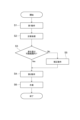
図8及び図9は、実施形態に係るロボットシステムの動作を表すフローチャートである。
図8は、図5(a)~図5(c)に表した動作を示す。まず、制御装置500は、第1動作(第1ステップ)を実行する(ステップS1)。第1動作では、アーム機構100が動作し、制御点の姿勢が所定の第1姿勢に設定される。制御装置500は、計算処理(計算ステップ)を実行する(ステップS2)。計算処理では、検出器400の検出結果に基づき、作業姿勢までの制御点の姿勢の変位量が計算される。制御装置500は、判定処理(判定ステップ)を実行する(ステップS3)。判定処理では、変位量が、可動部220の可動範囲内であるか判定される。
8 and 9 are flowcharts showing the operation of the robot system according to the embodiment.
FIG. 8 shows the operations shown in FIG. 5(a) to FIG. 5(c). First, the control device 500 executes a first operation (first step) (step S1). In the first operation, the
変位量が可動範囲内であるとき、制御装置500は、第2動作(第2ステップ)を実行する(ステップS4)。第2動作では、検出器400の検出結果に基づいてパラレルリンク機構200が動作し、制御点の姿勢が作業姿勢に設定される。変位量が可動範囲外であるとき、制御装置500は、補正動作(補正ステップ)を実行する(ステップS5)。補正動作では、アーム機構100が動作し、制御点の姿勢が作業姿勢に近づく。その後、第2動作が実行される。
When the displacement amount is within the movable range, the control device 500 executes a second operation (second step) (step S4). In the second operation, the
制御装置500は、作業を実行する(ステップS6)。作業は、エンドエフェクタ300を用いて実行される。作業中は、検出器400の検出結果に基づいて、制御点の姿勢が調整される。検出結果に基づく姿勢の調整は、パラレルリンク機構200により実行される。
The control device 500 executes the work (step S6). The work is executed using the
図9は、図6(a)、図6(b)、図7(a)、及び図7(b)に表した動作を示す。制御装置500は、第1動作を実行し(ステップS1)、計算処理を実行する(ステップS2)。計算処理では、検出器400の検出結果に基づき、作業対象Oに対して第1状態となる制御点の姿勢を計算する。制御装置500は、判定処理を実行する(ステップS3)。判定処理では、第1状態において、アーム機構100の先端部の姿勢が特異点近傍にあるか判定される。
Figure 9 shows the operations shown in Figures 6(a), 6(b), 7(a), and 7(b). The control device 500 executes a first operation (step S1), and executes a calculation process (step S2). In the calculation process, the attitude of the control point that is in the first state with respect to the work object O is calculated based on the detection result of the
第1状態においてアーム機構100の先端部の姿勢が特異点近傍にないとき、制御装置500は、第1補正動作を実行する(ステップS51)。第1補正動作では、アーム機構100が動作し、作業対象Oに対する制御点の姿勢が第1状態に設定される。第1状態においてアーム機構100の先端部の姿勢が特異点近傍にあるとき、制御装置500は、第2補正動作を実行する(ステップS52)。第2補正動作では、アーム機構100が動作し、作業対象Oに対する制御点の姿勢が第2状態に設定される。第1補正動作又は第2補正動作の後、制御装置500は、第2動作を実行し(ステップS4)、作業を実行する(ステップS6)。
When the attitude of the tip of the
図10は、実施形態に係るロボットシステムのエンドエフェクタを表す斜視図である。
図10を参照して、実施形態に係るロボットシステム1に用いられるエンドエフェクタ300の一例について説明する。図10に表した例では、エンドエフェクタ300として、検査器310及び塗布装置320が設けられている。この例では、作業対象Oは溶接された部材であり、作業として検査が実行される。また、制御点は、検査器310の先端に設定される。
FIG. 10 is a perspective view illustrating an end effector of the robot system according to the embodiment.
An example of an
検査器310は、溶接部を検査するための複数の超音波センサを含む。塗布装置320は、カプラントを溶接部の上面に塗布する。カプラントは、検査器310と検査対象との間で超音波の音響的整合をとるために用いられる。カプラントは、液体でも良いし、ゲル状でも良い。この例では、検出器400としてのカメラが、検査器310及び塗布装置320に隣接して設けられている。検出器400は、溶接された部材を撮影し、画像を取得する。検出器400は、画像から溶接痕を抽出し、溶接部の位置を検出する。
The
図11は、検査器先端の内部構造を表す斜視図である。
検査器310先端の内部には、図11に表したマトリクスセンサ311が設けられている。マトリクスセンサ311は、複数の超音波センサ312を含む。超音波センサ312は、例えば、トランスデューサである。複数の超音波センサ312は、互いに交差する2方向(X方向及びY方向)に沿って配列されている。この例では、X方向とY方向は、直交している。なお、複数の超音波センサ312が配列されるX方向及びY方向は、制御点の位置を示す座標系のX方向及びY方向と対応していても良いし、対応していなくても良い。
FIG. 11 is a perspective view showing the internal structure of the tip of the inspection device.
A
制御装置500は、パラレルリンク機構200を動かし、X方向及びY方向を含む面と交差するZ方向に沿って検査器310を移動させる。制御装置500は、検査器310を検査対象に接触させ、溶接部を検査する。
The control device 500 moves the
図11は、部材5を検査する様子を表している。部材5は、金属板51(第1部材)と金属板52(第2部材)が、溶接部53においてスポット溶接されて作製されている。溶接部53では、金属板51の一部と金属板52の一部が溶融し、混ざり合って凝固した凝固部54が形成されている。それぞれの超音波センサ312は、カプラント55が塗布された部材5に向けて超音波USを送信し、部材5からの反射波RWを受信する。
Figure 11 shows how
より具体的な一例として、図11に表したように、1つの超音波センサ312が溶接部53に向けて超音波USを送信する。超音波USの一部は、部材5の上面または下面などで反射される。複数の超音波センサ312のそれぞれは、この反射波RWを受信(検出)する。それぞれの超音波センサ312が順次超音波USを送信し、それぞれの反射波RWを複数の超音波センサ312で受信することで、部材5の溶接部53近傍を、2次元的に検査する。
As a more specific example, as shown in FIG. 11, one
図12は、検査器による検査方法を説明するための模式図である。
図12(a)に表したように、超音波USの一部は、金属板51の上面5aまたは溶接部53の上面5bで反射される。超音波USの別の一部は、部材5に入射し、金属板51の下面5cまたは溶接部53の下面5dで反射する。
FIG. 12 is a schematic diagram for explaining an inspection method using an inspection device.
12A, a portion of the ultrasonic wave US is reflected by the
上面5a、上面5b、下面5c、及び下面5dのZ方向における位置は、互いに異なる。すなわち、これらの面と超音波センサ312との間のZ方向における距離が、互いに異なる。超音波センサ312が、これらの面からの反射波を受信すると、反射波の強度のピークが検出される。超音波USを送信した後、各ピークが検出されるまでの時間を算出することで、どの面で超音波USが反射されているか調べることができる。
The positions in the Z direction of the
図12(b)及び図12(c)は、超音波USを送信した後の時間と、反射波RWの強度と、の関係を例示するグラフである。ここでは、反射波RWの強度を絶対値で表している。図12(b)のグラフは、金属板51の上面5a及び下面5cからの反射波RWの受信結果を例示している。図12(c)のグラフは、溶接部53の上面5b及び下面5dからの反射波RWの受信結果を例示している。
Figures 12(b) and 12(c) are graphs illustrating the relationship between the time after transmitting ultrasonic waves US and the intensity of the reflected waves RW. Here, the intensity of the reflected waves RW is expressed as an absolute value. The graph in Figure 12(b) illustrates the reception results of the reflected waves RW from the
図12(b)のグラフにおいて、1回目のピークPe1は、上面5aからの反射波RWに基づく。2回目のピークPe2は、下面5cからの反射波RWに基づく。ピークPe1及びピークPe2が検出された時間は、それぞれ、金属板51の上面5a及び下面5cのZ方向における位置に対応する。ピークPe1が検出された時間とピークPe2が検出された時間との時間差TD1は、上面5aと下面5cとの間のZ方向における距離Di1に対応する。
In the graph of FIG. 12(b), the first peak Pe1 is based on the reflected wave RW from the
同様に、図12(c)のグラフにおいて、1回目のピークPe3は、上面5bからの反射波RWに基づく。2回目のピークPe4は、下面5dからの反射波RWに基づく。ピークPe3及びピークPe4が検出された時間は、それぞれ、溶接部53の上面5b及び下面5dのZ方向における位置に対応する。ピークPe3が検出された時間とピークPe4が検出された時間との時間差TD2は、上面5bと下面5dとの間のZ方向における距離Di2に対応する。
Similarly, in the graph of FIG. 12(c), the first peak Pe3 is based on the reflected wave RW from the
制御装置500は、隣り合うピークの時間差から、溶接部53近傍の各点が溶接されているか検査する。また、溶接部53の上面5b及び下面5dは、金属板51の上面5aに対して傾斜していることがある。これは、溶接部53が凝固部54を含むことや、溶接の過程における形状の変形などに基づく。この場合、上面5b又は下面5dに対して平均的に垂直な方向に沿って超音波USが送信されることが望ましい。これにより、上面5b及び下面5dにおいてより強く超音波が反射され、検査の精度を向上させることができる。
The control device 500 checks whether each point near the welded
図13は、実施形態に係るロボットシステムによる検査の流れを表すフローチャートである。
まず、制御装置500は、第1動作を実行する(ステップS1)。検出器400は、部材5を撮影し、取得した画像から溶接部53の位置を検出する(ステップS11)。制御装置500は、第2動作を実行する(ステップS4)。これにより、検査器310及び塗布装置320の姿勢が調整される。ステップS11とS4との間に、図8又は図9に表した計算処理、判定処理、及び補正動作が実行されても良い。
FIG. 13 is a flowchart showing the flow of inspection by the robot system according to the embodiment.
First, the control device 500 executes a first operation (step S1). The
塗布装置320は、カプラント55を溶接部53に塗布する(ステップS12)。制御装置500は、パラレルリンク機構200を動かし、溶接部53が検出された位置に検査器310を接触させる(ステップS13)。検査器310が溶接部53に接触した状態で、制御装置500は、溶接部53を検査する(ステップS14)。
The
具体的には、複数の超音波センサ312が、溶接部53を含む部材5に向けて超音波USを送信し、反射波RWを受信する。検査器310は、反射波の受信結果を制御装置500に送信する。制御装置500は、受信結果から、溶接部53に対する検査器310の傾きを計算する。制御装置500は、計算結果に基づき、その傾きが小さくなるように、パラレルリンク機構200を動かして検査器310の先端の姿勢を調整する。
Specifically, multiple
検査器310の姿勢の調整後、複数の超音波センサ312は、超音波USを再度送信し、反射波RWを受信する。制御装置500は、この反射結果に基づき、溶接部53が適切に溶接されているか判定する。これにより、溶接部53の検査が完了する。制御装置500は、未検査の溶接部53があるか判定する(ステップS15)。未検査の溶接部53が無い場合、動作を終了する。未検査の溶接部53がある場合、制御装置500は、未検査の溶接部53に対して第1動作を再度実行する。
After adjusting the posture of the
以下では、傾きの算出方法について具体的な一例を説明する。
図14は、検査における傾きの計算方法を説明するための図である。
図15及び図16は、検査において得られた画像の一例である。
A specific example of a method for calculating the inclination will be described below.
FIG. 14 is a diagram for explaining a method of calculating the inclination in the inspection.
15 and 16 are examples of images obtained during the inspection.
図15は、反射波の検出結果に基づいて描写される3次元のボリュームデータである。図16(a)は、図15に表したボリュームデータにおける溶接部53の表面を表す。図16(b)は、図15に表したボリュームデータにおける溶接部53近傍のY-Z断面を表す。図16(c)は、図15に表したボリュームデータにおける溶接部53近傍のX-Z断面を表す。図16(b)及び図16(c)では、上側が溶接部53の表面で、下向きに深さ方向のデータが示されている。輝度が高い部分は、超音波の反射強度が大きい部分である。超音波は、溶接部53の底面、未接合の部材同士の間の面などで強く反射される。
Figure 15 is three-dimensional volume data depicted based on the detection results of the reflected waves. Figure 16(a) shows the surface of
検査器310の傾きは、図14に表した、溶接部53に垂直な方向53aと、検査器310の方向310aと、の間の角度に対応する。この角度は、X方向まわりの角度θxと、Y方向まわりの角度θyと、によって表される。検査器310の方向310aは、超音波センサ312の配列方向に対して垂直である。
The inclination of the
角度θxは、図16(b)に表したように、Y-Z断面での検出結果に基づいて算出される。角度θyは、図16(c)に表したように、X-Z断面での検出結果に基づいて算出される。制御装置500は、各断面について,3次元の輝度勾配の平均を角度θx及びθyとして算出する。制御装置500は、算出した角度θx及びθyを、検査器310の傾きとして、記憶装置510に記憶する。
The angle θx is calculated based on the detection results in the Y-Z cross section, as shown in FIG. 16(b). The angle θy is calculated based on the detection results in the X-Z cross section, as shown in FIG. 16(c). The control device 500 calculates the average of the three-dimensional brightness gradient for each cross section as angles θx and θy. The control device 500 stores the calculated angles θx and θy in the storage device 510 as the inclination of the
ここでは、制御装置500が、アーム機構100及びパラレルリンク機構200を制御し、検査に関する処理を実行する例を説明した。この例に限らず、アーム機構100及びパラレルリンク機構200を制御する制御装置と、検査に関する処理を実行する別の制御装置と、が設けられても良い。検査に関する処理は、ネットワークを介して別の制御装置又は処理装置により実行されても良い。
Here, an example has been described in which the control device 500 controls the
以上では、ロボットシステム1が、6自由度を有する垂直多関節のアーム機構100を含む例を説明した。この例に限らず、アーム機構100は、4自由度以上を有していれば良い。4自由度以上であれば、アーム機構100による制御点の大まかな姿勢の調整後に、パラレルリンク機構200を用いて制御点の細かな姿勢を調整できる。又は、4自由度以上を有する水平多関節のアーム機構100が設けられても良い。いずれの形態においても、パラレルリンク機構200を用いて制御点の姿勢を調整することで、フィードバック制御により制御点の姿勢を調整する場合においても、不安定な動作の発生を抑制できる。
In the above, an example has been described in which the
実施形態は、以下の構成を含む。
(構成1)
多関節のアーム機構と、
前記アーム機構の先端部に取り付けられる固定部、及び、
複数の並列なリンクを介して前記固定部に取り付けられ、前記固定部に対して可動な可動部、
を含むパラレルリンク機構と、
前記可動部に取り付けられ、作業対象への作業を実行するエンドエフェクタと、
前記可動部と前記作業対象との間の位置の関係又は向きの関係を検出するための検出器と、
前記アーム機構及び前記パラレルリンク機構を制御する制御装置と、
を備え、
前記制御装置は、前記エンドエフェクタによる作業時には、前記検出器による検出結果に基づき、前記パラレルリンク機構を動かして前記エンドエフェクタの姿勢を調整する、ロボットシステム。
The embodiment includes the following configurations.
(Configuration 1)
A multi-joint arm mechanism,
A fixing part attached to a tip end of the arm mechanism; and
a movable part attached to the fixed part via a plurality of parallel links and movable relative to the fixed part;
A parallel link mechanism including:
An end effector attached to the movable part and performing a task on a work object;
A detector for detecting a positional relationship or an orientation relationship between the movable part and the work object;
a control device for controlling the arm mechanism and the parallel link mechanism;
Equipped with
The control device, when the end effector is performing work, moves the parallel link mechanism to adjust the posture of the end effector based on the detection result by the detector.
以上で説明したロボットシステム、ロボットシステムの制御方法、又は制御装置を用いることで、フィードバック制御によりエンドエフェクタ300の姿勢を調整する場合においても、不安定な動作の発生を抑制できる。また、ロボットシステムの制御装置に、上述した制御方法を実行させるプログラムを用いることで、同様の効果を得ることができる。
By using the robot system, the control method for the robot system, or the control device described above, it is possible to prevent the occurrence of unstable operation even when adjusting the posture of the
上記の種々のデータの処理は、コンピュータに実行させることのできるプログラムとして、磁気ディスク(フレキシブルディスク及びハードディスクなど)、光ディスク(CD-ROM、CD-R、CD-RW、DVD-ROM、DVD±R、DVD±RWなど)、半導体メモリ、または、他の記録媒体に記録されても良い。 The above various data processing may be recorded as a program that can be executed by a computer on a magnetic disk (such as a flexible disk or hard disk), an optical disk (such as a CD-ROM, CD-R, CD-RW, DVD-ROM, DVD±R, DVD±RW), a semiconductor memory, or other recording medium.
例えば、記録媒体に記録されたデータは、コンピュータ(または組み込みシステム)により読み出されることが可能である。記録媒体において、記録形式(記憶形式)は任意である。例えば、コンピュータは、記録媒体からプログラムを読み出し、このプログラムに基づいてプログラムに記述されている指示をCPUで実行させる。コンピュータにおいて、プログラムの取得(または読み出し)は、ネットワークを通じて行われても良い。 For example, data recorded on a recording medium can be read by a computer (or an embedded system). The recording medium may have any recording format (storage format). For example, the computer reads a program from the recording medium and causes the CPU to execute the instructions described in the program based on the program. The computer may also acquire (or read) the program via a network.
以上、本発明のいくつかの実施形態を例示したが、これらの実施形態は、例として提示したものであり、発明の範囲を限定することは意図していない。これら新規な実施形態は、その他の様々な形態で実施されることが可能であり、発明の要旨を逸脱しない範囲で、種々の省略、置き換え、変更などを行うことができる。これら実施形態やその変形例は、発明の範囲や要旨に含まれるとともに、特許請求の範囲に記載された発明とその均等の範囲に含まれる。また、前述の各実施形態は、相互に組み合わせて実施することができる。 Although several embodiments of the present invention have been illustrated above, these embodiments are presented as examples and are not intended to limit the scope of the invention. These novel embodiments can be implemented in various other forms, and various omissions, substitutions, modifications, etc. can be made without departing from the gist of the invention. These embodiments and their variations are included within the scope and gist of the invention, as well as within the scope of the invention and its equivalents described in the claims. Furthermore, the above-mentioned embodiments can be implemented in combination with each other.
1 ロボットシステム、 100 アーム機構、 110 リンク、 121~126 回転軸、 130 基台、 200 パラレルリンク機構、 210 固定部、 211 孔、 220 可動部、 221 孔、 230,230a~230d リンク、 240,240a~240d アクチュエータ、 241 回転軸、 250 第1ジョイント部材、 251,252 継手、 260 第2ジョイント部材、 261 ボール、 262 ソケット、 270,270a~270d 回動アーム、 271 第1部分、 272 第2部分、 273 屈曲部、 300 エンドエフェクタ、 310 検査器、 311 マトリクスセンサ、 312 超音波センサ、 320 塗布装置、 400 検出器、 500 制御装置、 510 記憶装置、 520 入力装置、 530 出力装置、 O 作業対象 1 Robot system, 100 Arm mechanism, 110 Link, 121 to 126 Rotating shaft, 130 Base, 200 Parallel link mechanism, 210 Fixed part, 211 Hole, 220 Movable part, 221 Hole, 230, 230a to 230d Link, 240, 240a to 240d Actuator, 241 Rotating shaft, 250 First joint member, 251, 252 Joint, 260 Second joint member, 261 Ball, 262 Socket, 270, 270a to 270d Rotating arm, 271 First part, 272 Second part, 273 Bending part, 300 End effector, 310 Inspector, 311 Matrix sensor, 312 Ultrasonic sensor, 320 Coating device, 400 detector, 500 control device, 510 storage device, 520 input device, 530 output device, O work object
Claims (21)
前記アーム機構の先端部に取り付けられる固定部、及び、
複数の並列なリンクを介して前記固定部に取り付けられ、前記固定部に対して可動な可動部、
を含み、前記アーム機構に対して4以上の自由度を有するパラレルリンク機構と、
前記可動部に取り付けられ、超音波センサを含む検査器を有するエンドエフェクタと、
制御点の位置又は向きを検出する検出器と、
前記アーム機構及び前記パラレルリンク機構を制御する制御装置であって、
前記アーム機構を動かし、前記制御点の姿勢を所定の第1姿勢に設定する第1動作と、
前記第1動作の後に、前記検出器の検出結果に基づいて前記パラレルリンク機構を動かし、前記制御点の前記姿勢を前記エンドエフェクタが作業を実行する作業姿勢に設定する第2動作と、
を実行する、前記制御装置と、
を備え、
前記制御装置は、前記第2動作の後に、
前記超音波センサが作業対象へ超音波を送信したときの反射波の受信結果から、前記作業対象に対する前記検査器の傾きを計算し、
前記傾きが小さくなるように、前記パラレルリンク機構を動作させる、
ロボットシステム。 A multi-joint arm mechanism,
A fixing part attached to a tip end of the arm mechanism; and
a movable part attached to the fixed part via a plurality of parallel links and movable relative to the fixed part;
a parallel link mechanism having four or more degrees of freedom with respect to the arm mechanism;
an end effector attached to the movable part and having an inspection device including an ultrasonic sensor;
A detector for detecting a position or orientation of a control point;
A control device for controlling the arm mechanism and the parallel link mechanism,
a first operation of moving the arm mechanism to set the attitude of the control point to a predetermined first attitude;
a second operation of moving the parallel link mechanism based on a detection result of the detector after the first operation, and setting the posture of the control point to a working posture in which the end effector performs a task;
The control device executes the above-mentioned
Equipped with
The control device, after the second action,
Calculating an inclination of the inspection device with respect to the work object based on a reception result of a reflected wave when the ultrasonic sensor transmits ultrasonic waves to the work object;
operating the parallel link mechanism so as to reduce the inclination;
Robot system.
前記検出器の検出結果に基づき、前記作業姿勢までの前記制御点の前記姿勢の変位量を計算する計算処理と、
前記変位量が前記可動部の可動範囲内であるか判定する判定処理と、
を実行し、
前記制御装置は、前記判定処理において、前記変位量が前記可動範囲を超えるときには、前記アーム機構を動かして前記制御点の前記姿勢を前記作業姿勢に近づけた後に、前記第2動作を実行する、請求項1記載のロボットシステム。 The control device, between the first operation and the second operation,
A calculation process for calculating a displacement amount of the posture of the control point to the working posture based on the detection result of the detector;
a determination process of determining whether the displacement amount is within a movable range of the movable part;
Run
2. The robot system according to claim 1, wherein, when the displacement amount exceeds the movable range in the determination process, the control device moves the arm mechanism to bring the posture of the control point closer to the working posture, and then executes the second operation.
前記第1動作と前記第2動作の間に、前記検出器の検出結果に基づいて前記アーム機構を動かし、前記制御点の前記姿勢を補正姿勢に設定する補正動作を実行し、
前記補正動作において、前記アーム機構の先端部の前記姿勢が特異点近傍を外れるように前記補正姿勢を設定する、
請求項1記載のロボットシステム。 The control device includes:
a correction operation is performed between the first operation and the second operation, by moving the arm mechanism based on a detection result of the detector and setting the attitude of the control point to a corrected attitude;
In the correction operation, the correction posture is set so that the posture of the tip of the arm mechanism is not near a singular point.
The robot system according to claim 1 .
前記制御装置は、前記溶接部に対する前記検査器の前記傾きを計算する、請求項1~3のいずれか1つに記載のロボットシステム。 The work target includes a plurality of members and a welded portion where the members are joined together,
The robot system according to any one of claims 1 to 3, wherein the control device calculates the inclination of the inspector relative to the welded portion.
前記パラレルリンク機構は、前記アーム機構に対して6自由度を有し、
前記制御装置は、前記第1配列方向と、前記第2配列方向と、前記第1配列方向及び前記第2配列方向を含む面と交差する交差方向と、における前記反射波の強度の勾配を計算し、前記勾配を用いて前記傾きを計算する、請求項4に記載のロボットシステム。 The ultrasonic sensors are arranged in a first arrangement direction and a second arrangement direction intersecting the first arrangement direction,
the parallel link mechanism has six degrees of freedom with respect to the arm mechanism,
5. The robot system of claim 4, wherein the control device calculates a gradient of intensity of the reflected wave in the first arrangement direction, the second arrangement direction, and an intersecting direction that intersects with a plane including the first arrangement direction and the second arrangement direction, and calculates the inclination using the gradient.
前記固定部に取り付けられ、回転軸が前記固定部から前記可動部に向かう第1方向と交差する方向に沿って設けられるアクチュエータと、
前記回転軸と連結される第1部分を有し、前記アクチュエータによって回動される回動アームと、
前記回動アームの第2部分と第1ジョイント部材を介して連結され、前記可動部と第2ジョイント部材を介して連結されたリンクと、
をさらに含み、
前記回動アームの前記第1部分と前記第2部分との間には、屈曲部が設けられ、
前記第2部分は、前記第1部分に対して前記可動部側に設けられる、請求項1~5のいずれか1つに記載のロボットシステム。 The parallel link mechanism includes:
an actuator attached to the fixed portion and having a rotation axis extending in a direction intersecting a first direction from the fixed portion toward the movable portion;
a rotating arm having a first portion connected to the rotating shaft and rotated by the actuator;
a link connected to the second portion of the pivot arm via a first joint member and connected to the movable portion via a second joint member;
Further comprising:
A bent portion is provided between the first portion and the second portion of the pivot arm,
The robot system according to any one of claims 1 to 5, wherein the second portion is provided on the movable portion side relative to the first portion.
前記可動部は、
前記エンドエフェクタが取り付けられる第2面と、
前記第1方向に対して傾斜し、前記第1方向を向いた第3面と、
を有し、
前記第2面のサイズは、前記第1面のサイズよりも小さく、
前記第2ジョイント部材は、前記第3面に取り付けられる請求項6記載のロボットシステム。 the fixed portion has a first surface to which the actuator is attached,
The movable part is
a second surface to which the end effector is attached; and
a third surface inclined with respect to the first direction and facing the first direction;
having
The size of the second surface is smaller than the size of the first surface,
The robot system of claim 6 , wherein the second joint member is attached to the third surface.
前記可動部には、前記第1方向に沿って前記可動部を貫通する第2孔が設けられた請求項6又は7に記載のロボットシステム。 The fixing portion is provided with a first hole penetrating the fixing portion along the first direction,
The robot system according to claim 6 or 7, wherein the movable portion is provided with a second hole penetrating the movable portion along the first direction.
前記アーム機構の先端部に取り付けられる固定部、及び、
複数の並列なリンクを介して前記固定部に取り付けられ、前記固定部に対して可動な可動部、
を含み、前記アーム機構に対して4以上の自由度を有するパラレルリンク機構と、
前記可動部に取り付けられ、超音波センサを含む検査器を有するエンドエフェクタと、
制御点の位置又は向きを検出する検出器と、
を含むロボットシステムの制御方法であって、
前記アーム機構を動かし、前記制御点の姿勢を所定の第1姿勢に設定する第1ステップと、
前記第1ステップの後に、前記検出器の検出結果に基づいて前記パラレルリンク機構を動かし、前記制御点の前記姿勢を前記エンドエフェクタが作業を実行する作業姿勢に設定する第2ステップと、
を備え、
前記第2ステップの後に、前記超音波センサが作業対象へ超音波を送信したときの反射波の受信結果から、前記作業対象に対する前記検査器の傾きを計算し、前記傾きが小さくなるように、前記パラレルリンク機構を動作させる、制御方法。 A multi-joint arm mechanism,
A fixing part attached to a tip end of the arm mechanism; and
a movable part attached to the fixed part via a plurality of parallel links and movable relative to the fixed part;
a parallel link mechanism having four or more degrees of freedom with respect to the arm mechanism;
an end effector attached to the movable part and having an inspection device including an ultrasonic sensor;
A detector for detecting a position or orientation of a control point;
A method for controlling a robot system, comprising:
a first step of moving the arm mechanism to set the attitude of the control point to a predetermined first attitude;
a second step of moving the parallel link mechanism based on a detection result of the detector after the first step, and setting the posture of the control point to a working posture in which the end effector performs a task;
Equipped with
A control method comprising: after the second step, calculating an inclination of the inspection device with respect to the work object from a reception result of a reflected wave when the ultrasonic sensor transmits ultrasonic waves to the work object; and operating the parallel link mechanism so as to reduce the inclination.
前記変位量が前記可動部の可動範囲内であるか判定する判定ステップと、
をさらに備え、
前記計算ステップ及び前記判定ステップは、前記第1ステップと前記第2ステップとの間に実行され、
前記判定ステップにおいて、前記変位量が前記可動範囲を超えるときには、前記アーム機構を動かして前記制御点の前記姿勢を前記作業姿勢に近づけた後に、前記第2ステップを実行する、請求項9記載の制御方法。 a calculation step of calculating a displacement amount of the posture of the control point to the working posture based on a detection result of the detector;
a determination step of determining whether the displacement amount is within a movable range of the movable part;
Further equipped with
the calculating step and the determining step are performed between the first step and the second step;
10. The control method according to claim 9, wherein, when the amount of displacement exceeds the movable range in the determining step, the arm mechanism is moved to bring the attitude of the control point closer to the working attitude, and then the second step is executed.
前記補正ステップは、前記第1ステップと前記第2ステップとの間に実行され、
前記補正ステップにおいて、前記アーム機構の先端部の前記姿勢が特異点近傍を外れるように前記補正姿勢を設定する、請求項9記載の制御方法。 a correction step of moving the arm mechanism based on a detection result of the detector and setting the attitude of the control point to a corrected attitude,
The correction step is performed between the first step and the second step;
10. The control method according to claim 9, wherein in the correcting step, the corrected attitude is set so that the attitude of the tip end of the arm mechanism is not near a singular point.
前記アーム機構の先端部に取り付けられる固定部、及び、
複数の並列なリンクを介して前記固定部に取り付けられ、前記固定部に対して可動な可動部、
を含み、前記アーム機構に対して4以上の自由度を有するパラレルリンク機構と、
前記可動部に取り付けられ、超音波センサを含む検査器を有するエンドエフェクタと、
制御点の位置又は向きを検出する検出器と、
を含むロボットシステムを制御する制御装置であって、
前記アーム機構を動かし、前記制御点の姿勢を所定の第1姿勢に設定する第1動作と、
前記第1動作の後に、前記検出器の検出結果に基づいて前記パラレルリンク機構を動かし、前記制御点の前記姿勢を前記エンドエフェクタが作業を実行する作業姿勢に設定する第2動作と、
を実行し、
前記第2動作の後に、前記超音波センサが作業対象へ超音波を送信したときの反射波の受信結果から、前記作業対象に対する前記検査器の傾きを計算し、前記傾きが小さくなるように前記パラレルリンク機構を動作させる、制御装置。 A multi-joint arm mechanism,
A fixing part attached to a tip end of the arm mechanism; and
a movable part attached to the fixed part via a plurality of parallel links and movable relative to the fixed part;
a parallel link mechanism having four or more degrees of freedom with respect to the arm mechanism;
an end effector attached to the movable part and having an inspection device including an ultrasonic sensor;
A detector for detecting a position or orientation of a control point;
A control device for controlling a robot system including:
a first operation of moving the arm mechanism to set the attitude of the control point to a predetermined first attitude;
a second operation of moving the parallel link mechanism based on a detection result of the detector after the first operation, and setting the posture of the control point to a working posture in which the end effector performs a task;
Run
a control device that calculates an inclination of the inspection device relative to the work object from a reception result of a reflected wave when the ultrasonic sensor transmits ultrasonic waves to the work object after the second operation, and operates the parallel link mechanism so as to reduce the inclination.
前記検出器の検出結果に基づき、前記作業姿勢までの前記制御点の前記姿勢の変位量を計算する計算処理と、
前記変位量が前記可動部の可動範囲内であるか判定する判定処理と、
をさらに実行し、
前記判定処理において、前記変位量が前記可動範囲を超えるときには、前記アーム機構を動かして前記制御点の前記姿勢を前記作業姿勢に近づけた後に、前記第2動作を実行する、請求項13記載の制御装置。 Between the first and second movements,
A calculation process for calculating a displacement amount of the posture of the control point to the working posture based on the detection result of the detector;
a determination process of determining whether the displacement amount is within a movable range of the movable part;
Further execute
The control device according to claim 13 , wherein, when the amount of displacement exceeds the movable range in the determination process, the second action is executed after the arm mechanism is moved to bring the attitude of the control point closer to the working attitude.
前記補正動作において、前記アーム機構の先端部の前記姿勢が特異点近傍を外れるように前記補正姿勢を設定する、請求項13記載の制御装置。 a correction operation is performed between the first operation and the second operation, by moving the arm mechanism based on a detection result of the detector and setting the attitude of the control point to a corrected attitude;
The control device according to claim 13 , wherein in the correcting operation, the corrected attitude is set so that the attitude of the tip of the arm mechanism is not near a singular point.
前記アーム機構の先端部に取り付けられる固定部、及び、
複数の並列なリンクを介して前記固定部に取り付けられ、前記固定部に対して可動な可動部、
を含み、前記アーム機構に対して4以上の自由度を有するパラレルリンク機構と、
前記可動部に取り付けられ、超音波センサを含む検査器を有するエンドエフェクタと、
制御点の位置又は向きを検出する検出器と、
を含むロボットシステムを制御する制御装置に対して、
前記アーム機構を動かし、前記制御点の姿勢を所定の第1姿勢に設定する第1動作と、
前記第1動作の後に、前記検出器の検出結果に基づいて前記パラレルリンク機構を動かし、前記制御点の前記姿勢を前記エンドエフェクタが作業を実行する作業姿勢に設定する第2動作と、
を実行させ、
前記第2動作の後に、前記超音波センサが作業対象へ超音波を送信したときの反射波の受信結果から、前記作業対象に対する前記検査器の傾きを計算させ、前記傾きが小さくなるように、前記パラレルリンク機構を動作させる、プログラム。 A multi-joint arm mechanism,
A fixing part attached to a tip end of the arm mechanism; and
a movable part attached to the fixed part via a plurality of parallel links and movable relative to the fixed part;
a parallel link mechanism having four or more degrees of freedom with respect to the arm mechanism;
an end effector attached to the movable part and having an inspection device including an ultrasonic sensor;
A detector for detecting a position or orientation of a control point;
A control device for controlling a robot system including:
a first operation of moving the arm mechanism to set the attitude of the control point to a predetermined first attitude;
a second operation of moving the parallel link mechanism based on a detection result of the detector after the first operation, and setting the posture of the control point to a working posture in which the end effector performs a task;
Run the command,
a program that, after the second operation, calculates an inclination of the inspection device relative to the work object from a reception result of a reflected wave when the ultrasonic sensor transmits ultrasonic waves to the work object, and operates the parallel link mechanism so as to reduce the inclination.
前記検出器の検出結果に基づき、前記作業姿勢までの前記制御点の前記姿勢の変位量を計算する計算処理と、
前記変位量が前記可動部の可動範囲内であるか判定する判定処理と、
をさらに実行させ、
前記判定処理において、前記変位量が前記可動範囲を超えるときには、前記アーム機構を動かして前記制御点の前記姿勢を前記作業姿勢に近づけた後に、前記第2動作を実行させる請求項17記載のプログラム。 The control device, between the first operation and the second operation,
A calculation process for calculating a displacement amount of the posture of the control point to the working posture based on the detection result of the detector;
a determination process of determining whether the displacement amount is within a movable range of the movable part;
Then,
The program according to claim 17 , wherein, in the determination process, when the amount of displacement exceeds the movable range, the arm mechanism is moved to bring the posture of the control point closer to the working posture, and then the second operation is executed.
前記補正動作において、前記アーム機構の先端部の前記姿勢が特異点近傍を外れるように前記補正姿勢を設定する、請求項17記載のプログラム。 causing the control device to execute a correction operation between the first operation and the second operation, by moving the arm mechanism based on a detection result of the detector and setting the attitude of the control point to a corrected attitude;
The program according to claim 17 , wherein in the correcting operation, the corrected attitude is set so that the attitude of the tip of the arm mechanism is not near a singular point.
Priority Applications (5)
| Application Number | Priority Date | Filing Date | Title |
|---|---|---|---|
| JP2020040214A JP7462437B2 (en) | 2020-03-09 | 2020-03-09 | ROBOT SYSTEM, PARALLEL LINK MECHANISM, CONTROL METHOD, CONTROL DEVICE, PROGRAM, AND STORAGE MEDIUM |
| PCT/JP2021/005497 WO2021182024A1 (en) | 2020-03-09 | 2021-02-15 | Robot system, parallel link mechanism, control method, control device, program, and storage medium |
| CN202180019815.2A CN115279555A (en) | 2020-03-09 | 2021-02-15 | Robot system, parallel link mechanism, control method, control device, program, and storage medium |
| EP21766915.9A EP4119301A4 (en) | 2020-03-09 | 2021-02-15 | Robot system, parallel link mechanism, control method, control device, program, and storage medium |
| US17/930,270 US12330308B2 (en) | 2020-03-09 | 2022-09-07 | Robot system, parallel link mechanism, control method, control device, and storage medium |
Applications Claiming Priority (1)
| Application Number | Priority Date | Filing Date | Title |
|---|---|---|---|
| JP2020040214A JP7462437B2 (en) | 2020-03-09 | 2020-03-09 | ROBOT SYSTEM, PARALLEL LINK MECHANISM, CONTROL METHOD, CONTROL DEVICE, PROGRAM, AND STORAGE MEDIUM |
Publications (3)
| Publication Number | Publication Date |
|---|---|
| JP2021137939A JP2021137939A (en) | 2021-09-16 |
| JP2021137939A5 JP2021137939A5 (en) | 2022-11-02 |
| JP7462437B2 true JP7462437B2 (en) | 2024-04-05 |
Family
ID=77667429
Family Applications (1)
| Application Number | Title | Priority Date | Filing Date |
|---|---|---|---|
| JP2020040214A Active JP7462437B2 (en) | 2020-03-09 | 2020-03-09 | ROBOT SYSTEM, PARALLEL LINK MECHANISM, CONTROL METHOD, CONTROL DEVICE, PROGRAM, AND STORAGE MEDIUM |
Country Status (5)
| Country | Link |
|---|---|
| US (1) | US12330308B2 (en) |
| EP (1) | EP4119301A4 (en) |
| JP (1) | JP7462437B2 (en) |
| CN (1) | CN115279555A (en) |
| WO (1) | WO2021182024A1 (en) |
Families Citing this family (8)
| Publication number | Priority date | Publication date | Assignee | Title |
|---|---|---|---|---|
| JP7426858B2 (en) * | 2020-03-10 | 2024-02-02 | 株式会社大気社 | Inspection equipment and inspection method |
| JP7438886B2 (en) | 2020-08-07 | 2024-02-27 | 株式会社東芝 | Detection system, control method, and detection device |
| US12427667B2 (en) * | 2021-08-31 | 2025-09-30 | Canon Kabushiki Kaisha | Robot system, method for controlling robot system, method for manufacturing article using robot system, system, method for controlling system, and recording medium |
| US20250142214A1 (en) * | 2021-10-04 | 2025-05-01 | Sony Group Corporation | Mobile apparatus, information processing program, and information processing method |
| JP7754760B2 (en) * | 2022-03-22 | 2025-10-15 | 株式会社東芝 | Parallel link mechanism, robot mechanism, and braking method |
| CN115373343B (en) * | 2022-04-30 | 2024-05-14 | 江苏普旭科技股份有限公司 | Parallel six-degree-of-freedom motion platform control system and control method |
| JP2024011613A (en) * | 2022-07-15 | 2024-01-25 | 日鉄エンジニアリング株式会社 | control system |
| JP2024045929A (en) * | 2022-09-22 | 2024-04-03 | セイコーエプソン株式会社 | Robot teaching method and three-dimensional object printing device |
Citations (10)
| Publication number | Priority date | Publication date | Assignee | Title |
|---|---|---|---|---|
| JP2002239958A (en) | 2001-02-20 | 2002-08-28 | Fukui Prefecture | Parallel mechanism robot arm (2) |
| JP2003071760A (en) | 2001-08-31 | 2003-03-12 | Ricoh Co Ltd | Assembly robot |
| JP2005528993A (en) | 2002-06-13 | 2005-09-29 | ローベルト ボツシユ ゲゼルシヤフト ミツト ベシユレンクテル ハフツング | Delta robot |
| JP2008126219A (en) | 2006-11-25 | 2008-06-05 | Hirosaki Univ | Application system |
| JP2010082333A (en) | 2008-10-01 | 2010-04-15 | Tokyo Univ Of Agriculture & Technology | Ultrasonic inspection robot system, and control method for ultrasonic inspection robot |
| JP2010247238A (en) | 2009-04-10 | 2010-11-04 | Olympus Corp | Parallel link stage and optical element measuring instrument |
| WO2017017712A1 (en) | 2015-07-30 | 2017-02-02 | Nec Corporation | Linear motion mechanism formed integrally |
| JP2018202602A (en) | 2017-05-31 | 2018-12-27 | セイコーエプソン株式会社 | Control device, robot, and control method |
| JP2019048343A (en) | 2017-09-08 | 2019-03-28 | Ntn株式会社 | Work device using parallel link mechanism |
| JP2019090727A (en) | 2017-11-15 | 2019-06-13 | 株式会社東芝 | Inspection system, angle adjustment method, program, and storage medium |
Family Cites Families (25)
| Publication number | Priority date | Publication date | Assignee | Title |
|---|---|---|---|---|
| JPS60249588A (en) * | 1984-05-24 | 1985-12-10 | 住友電気工業株式会社 | positioning mechanism |
| JPH0677205B2 (en) * | 1985-06-03 | 1994-09-28 | 株式会社日立製作所 | Robot control method |
| JP4719010B2 (en) | 2005-01-21 | 2011-07-06 | 日本電産サンキョー株式会社 | Industrial robot |
| JP2010278906A (en) | 2009-05-29 | 2010-12-09 | Fujitsu Optical Components Ltd | Delay interferometer and optical receiver |
| JP5886140B2 (en) | 2012-05-30 | 2016-03-16 | 株式会社Skb | Switchgear |
| JP5576912B2 (en) * | 2012-09-03 | 2014-08-20 | ファナック株式会社 | Parallel link robot with additional actuators located on the passive link |
| SE537534C2 (en) | 2013-08-27 | 2015-06-02 | Cognibotics Ab | Method and system for determining at least one property of a manipulator |
| WO2015142801A1 (en) * | 2014-03-17 | 2015-09-24 | Intuitive Surgical Operations, Inc. | Methods of controlling motion of under-actuated joints in a surgical set-up structure |
| US10350766B2 (en) | 2015-09-21 | 2019-07-16 | GM Global Technology Operations LLC | Extended-reach assist device for performing assembly tasks |
| DE102016218180B4 (en) * | 2015-09-21 | 2019-12-12 | GM Global Technology Operations LLC | Extended gripping aid device with extended range for carrying out assembly tasks |
| JP6765221B2 (en) * | 2016-05-30 | 2020-10-07 | Ntn株式会社 | Work equipment using a parallel link mechanism |
| JP7061119B2 (en) | 2016-07-15 | 2022-04-27 | ファストブリック・アイピー・プロプライエタリー・リミテッド | Brick / block laying machine built into the vehicle |
| JP6514156B2 (en) * | 2016-08-17 | 2019-05-15 | ファナック株式会社 | Robot controller |
| DE102016215744A1 (en) * | 2016-08-23 | 2018-03-01 | Hartmut Ilch | industrial robots |
| CN107813290A (en) * | 2016-09-12 | 2018-03-20 | 马建群 | Serial-parallel hybrid robotic arm |
| JP2018167350A (en) | 2017-03-29 | 2018-11-01 | Ntn株式会社 | Multi joint robot |
| CN108972572B (en) | 2017-05-31 | 2022-10-28 | 精工爱普生株式会社 | Control device, robot, and control method |
| TWI639906B (en) | 2017-06-16 | 2018-11-01 | 中原大學 | Active assembly system, active assembly method and positioning assembly device thereof |
| JP7150446B2 (en) | 2018-02-26 | 2022-10-11 | Ntn株式会社 | Work device using parallel link mechanism |
| WO2019049972A1 (en) | 2017-09-08 | 2019-03-14 | Ntn株式会社 | Work device using parallel link mechanism |
| JP2019063902A (en) | 2017-09-29 | 2019-04-25 | Ntn株式会社 | Articulated robot and its operation method |
| CN208961995U (en) * | 2018-06-20 | 2019-06-11 | 江苏安全技术职业学院 | A kind of platform based on six-degree-of-freedom parallel robot |
| JP2020044610A (en) * | 2018-09-19 | 2020-03-26 | 株式会社デンソーウェーブ | Robot control method |
| JP7214589B2 (en) * | 2019-07-30 | 2023-01-30 | 株式会社東芝 | Inspection system, angle adjustment method, program, and storage medium |
| CN110450142B (en) * | 2019-09-09 | 2024-08-20 | 哈工大机器人(合肥)国际创新研究院 | Six-degree-of-freedom parallel robot based on double gyroscope components |
-
2020
- 2020-03-09 JP JP2020040214A patent/JP7462437B2/en active Active
-
2021
- 2021-02-15 EP EP21766915.9A patent/EP4119301A4/en active Pending
- 2021-02-15 WO PCT/JP2021/005497 patent/WO2021182024A1/en not_active Ceased
- 2021-02-15 CN CN202180019815.2A patent/CN115279555A/en active Pending
-
2022
- 2022-09-07 US US17/930,270 patent/US12330308B2/en active Active
Patent Citations (10)
| Publication number | Priority date | Publication date | Assignee | Title |
|---|---|---|---|---|
| JP2002239958A (en) | 2001-02-20 | 2002-08-28 | Fukui Prefecture | Parallel mechanism robot arm (2) |
| JP2003071760A (en) | 2001-08-31 | 2003-03-12 | Ricoh Co Ltd | Assembly robot |
| JP2005528993A (en) | 2002-06-13 | 2005-09-29 | ローベルト ボツシユ ゲゼルシヤフト ミツト ベシユレンクテル ハフツング | Delta robot |
| JP2008126219A (en) | 2006-11-25 | 2008-06-05 | Hirosaki Univ | Application system |
| JP2010082333A (en) | 2008-10-01 | 2010-04-15 | Tokyo Univ Of Agriculture & Technology | Ultrasonic inspection robot system, and control method for ultrasonic inspection robot |
| JP2010247238A (en) | 2009-04-10 | 2010-11-04 | Olympus Corp | Parallel link stage and optical element measuring instrument |
| WO2017017712A1 (en) | 2015-07-30 | 2017-02-02 | Nec Corporation | Linear motion mechanism formed integrally |
| JP2018202602A (en) | 2017-05-31 | 2018-12-27 | セイコーエプソン株式会社 | Control device, robot, and control method |
| JP2019048343A (en) | 2017-09-08 | 2019-03-28 | Ntn株式会社 | Work device using parallel link mechanism |
| JP2019090727A (en) | 2017-11-15 | 2019-06-13 | 株式会社東芝 | Inspection system, angle adjustment method, program, and storage medium |
Also Published As
| Publication number | Publication date |
|---|---|
| US12330308B2 (en) | 2025-06-17 |
| JP2021137939A (en) | 2021-09-16 |
| WO2021182024A1 (en) | 2021-09-16 |
| EP4119301A1 (en) | 2023-01-18 |
| EP4119301A4 (en) | 2024-03-27 |
| US20230001581A1 (en) | 2023-01-05 |
| CN115279555A (en) | 2022-11-01 |
Similar Documents
| Publication | Publication Date | Title |
|---|---|---|
| JP7462437B2 (en) | ROBOT SYSTEM, PARALLEL LINK MECHANISM, CONTROL METHOD, CONTROL DEVICE, PROGRAM, AND STORAGE MEDIUM | |
| CN108858183B (en) | Robot, robot control method, workpiece manufacturing method | |
| US10836042B2 (en) | Robot system | |
| US20120277898A1 (en) | Processing system and processing method | |
| JP5531996B2 (en) | 6-axis robot offset detection method | |
| JP6950638B2 (en) | Manipulator controller, manipulator control method, and manipulator control program | |
| CN109514599B (en) | Robot system and method for manufacturing workpiece | |
| JPH11502776A (en) | Apparatus and method for calibration of multi-axis industrial robot | |
| JP5672173B2 (en) | 6-axis robot offset detection method | |
| JPS63135814A (en) | Apparatus for controlling posture of probe | |
| US12461073B2 (en) | Detection system, control method, and detection device | |
| JP2019188500A (en) | Robot control method | |
| JP2017007082A (en) | Robot system and robot control method | |
| CN115943019A (en) | robot controller | |
| US20210146542A1 (en) | Control method for robot system | |
| JP2019030923A (en) | Robot arm, robot device, and robot system | |
| US20160375580A1 (en) | Robot system and robot control method | |
| EP4122658A1 (en) | Control device, inspection system, control method, program, and storage medium | |
| Baeten et al. | Tool/camera configurations for eye-in-hand hybrid vision/force control | |
| JP4791168B2 (en) | Positioning robot | |
| JP7462827B2 (en) | CONTROL DEVICE, ROBOT SYSTEM, LEARNING DEVICE, TRAJECTORY MODEL, CONTROL METHOD, AND PROGRAM | |
| JP2025127798A (en) | Rotating tool, method for calculating position and attitude of rotating tool, and system for calculating position and attitude of rotating tool | |
| JP2024145832A (en) | Friction stir welding method and friction stir welding system | |
| CN116749167A (en) | control device | |
| JP2008055518A (en) | Control method of welding robot |
Legal Events
| Date | Code | Title | Description |
|---|---|---|---|
| A521 | Request for written amendment filed |
Free format text: JAPANESE INTERMEDIATE CODE: A523 Effective date: 20221025 |
|
| A621 | Written request for application examination |
Free format text: JAPANESE INTERMEDIATE CODE: A621 Effective date: 20221025 |
|
| RD01 | Notification of change of attorney |
Free format text: JAPANESE INTERMEDIATE CODE: A7421 Effective date: 20230616 |
|
| A131 | Notification of reasons for refusal |
Free format text: JAPANESE INTERMEDIATE CODE: A131 Effective date: 20230725 |
|
| A521 | Request for written amendment filed |
Free format text: JAPANESE INTERMEDIATE CODE: A523 Effective date: 20230921 |
|
| A131 | Notification of reasons for refusal |
Free format text: JAPANESE INTERMEDIATE CODE: A131 Effective date: 20231215 |
|
| A521 | Request for written amendment filed |
Free format text: JAPANESE INTERMEDIATE CODE: A523 Effective date: 20240213 |
|
| TRDD | Decision of grant or rejection written | ||
| A01 | Written decision to grant a patent or to grant a registration (utility model) |
Free format text: JAPANESE INTERMEDIATE CODE: A01 Effective date: 20240226 |
|
| A61 | First payment of annual fees (during grant procedure) |
Free format text: JAPANESE INTERMEDIATE CODE: A61 Effective date: 20240326 |
|
| R150 | Certificate of patent or registration of utility model |
Ref document number: 7462437 Country of ref document: JP Free format text: JAPANESE INTERMEDIATE CODE: R150 |