JP2011232425A - Fixing apparatus and image forming apparatus - Google Patents
Fixing apparatus and image forming apparatus Download PDFInfo
- Publication number
- JP2011232425A JP2011232425A JP2010100688A JP2010100688A JP2011232425A JP 2011232425 A JP2011232425 A JP 2011232425A JP 2010100688 A JP2010100688 A JP 2010100688A JP 2010100688 A JP2010100688 A JP 2010100688A JP 2011232425 A JP2011232425 A JP 2011232425A
- Authority
- JP
- Japan
- Prior art keywords
- fixing
- air
- fan motor
- fixing device
- valve
- Prior art date
- Legal status (The legal status is an assumption and is not a legal conclusion. Google has not performed a legal analysis and makes no representation as to the accuracy of the status listed.)
- Granted
Links
- 239000000463 material Substances 0.000 claims abstract description 22
- 230000000903 blocking effect Effects 0.000 claims description 17
- 238000010438 heat treatment Methods 0.000 claims description 17
- 230000005484 gravity Effects 0.000 claims description 3
- 238000007664 blowing Methods 0.000 abstract description 2
- 230000002265 prevention Effects 0.000 abstract 1
- 238000000926 separation method Methods 0.000 description 10
- 229910052736 halogen Inorganic materials 0.000 description 7
- 150000002367 halogens Chemical class 0.000 description 7
- 239000010410 layer Substances 0.000 description 7
- 238000004140 cleaning Methods 0.000 description 5
- XLYOFNOQVPJJNP-UHFFFAOYSA-N water Chemical compound O XLYOFNOQVPJJNP-UHFFFAOYSA-N 0.000 description 5
- 229920001774 Perfluoroether Polymers 0.000 description 4
- 238000010586 diagram Methods 0.000 description 4
- 229920006015 heat resistant resin Polymers 0.000 description 4
- 229920002379 silicone rubber Polymers 0.000 description 4
- 229920001971 elastomer Polymers 0.000 description 3
- 229910052751 metal Inorganic materials 0.000 description 3
- 239000002184 metal Substances 0.000 description 3
- 230000002093 peripheral effect Effects 0.000 description 3
- 229920005989 resin Polymers 0.000 description 3
- 239000011347 resin Substances 0.000 description 3
- XEEYBQQBJWHFJM-UHFFFAOYSA-N Iron Chemical compound [Fe] XEEYBQQBJWHFJM-UHFFFAOYSA-N 0.000 description 2
- 239000000853 adhesive Substances 0.000 description 2
- 230000001070 adhesive effect Effects 0.000 description 2
- 229910052782 aluminium Inorganic materials 0.000 description 2
- XAGFODPZIPBFFR-UHFFFAOYSA-N aluminium Chemical compound [Al] XAGFODPZIPBFFR-UHFFFAOYSA-N 0.000 description 2
- 238000006243 chemical reaction Methods 0.000 description 2
- 210000000078 claw Anatomy 0.000 description 2
- 230000006835 compression Effects 0.000 description 2
- 238000007906 compression Methods 0.000 description 2
- 230000007423 decrease Effects 0.000 description 2
- 238000000034 method Methods 0.000 description 2
- 229920001343 polytetrafluoroethylene Polymers 0.000 description 2
- 239000004810 polytetrafluoroethylene Substances 0.000 description 2
- 238000003825 pressing Methods 0.000 description 2
- 239000007787 solid Substances 0.000 description 2
- YCKRFDGAMUMZLT-UHFFFAOYSA-N Fluorine atom Chemical compound [F] YCKRFDGAMUMZLT-UHFFFAOYSA-N 0.000 description 1
- 239000004642 Polyimide Substances 0.000 description 1
- 238000003705 background correction Methods 0.000 description 1
- 238000005452 bending Methods 0.000 description 1
- 239000011230 binding agent Substances 0.000 description 1
- 230000015572 biosynthetic process Effects 0.000 description 1
- 239000003795 chemical substances by application Substances 0.000 description 1
- 239000011248 coating agent Substances 0.000 description 1
- 238000000576 coating method Methods 0.000 description 1
- 239000003086 colorant Substances 0.000 description 1
- 238000009833 condensation Methods 0.000 description 1
- 230000005494 condensation Effects 0.000 description 1
- 238000009826 distribution Methods 0.000 description 1
- 230000005284 excitation Effects 0.000 description 1
- 229910052731 fluorine Inorganic materials 0.000 description 1
- 239000011737 fluorine Substances 0.000 description 1
- 230000020169 heat generation Effects 0.000 description 1
- 230000006698 induction Effects 0.000 description 1
- 229910052742 iron Inorganic materials 0.000 description 1
- 230000003287 optical effect Effects 0.000 description 1
- 239000002245 particle Substances 0.000 description 1
- 239000000049 pigment Substances 0.000 description 1
- 229920001721 polyimide Polymers 0.000 description 1
- -1 polytetrafluoroethylene Polymers 0.000 description 1
- 230000004043 responsiveness Effects 0.000 description 1
- 230000000630 rising effect Effects 0.000 description 1
- 238000004904 shortening Methods 0.000 description 1
- 229920002545 silicone oil Polymers 0.000 description 1
- 239000004945 silicone rubber Substances 0.000 description 1
- 230000003068 static effect Effects 0.000 description 1
- 239000002344 surface layer Substances 0.000 description 1
- 238000011144 upstream manufacturing Methods 0.000 description 1
- 230000037303 wrinkles Effects 0.000 description 1
Images


Landscapes
- Fixing For Electrophotography (AREA)
- Control Or Security For Electrophotography (AREA)
Abstract
Description
本発明は、定着部材と加圧部材とにより形成されたニップ部で記録材上のトナー像を定着する定着装置に関する。 The present invention relates to a fixing device that fixes a toner image on a recording material at a nip formed by a fixing member and a pressure member.
複写機、プリンタ、ファクシミリ及びこれらの諸機能を備えた複合機等の電子写真方式の画像形成装置においては、原稿に対応した潜像を感光体に形成し、この潜像にトナーを付与することによって顕像化し、この顕像化されたトナー像を記録紙上に転写し、この後、記録紙上に転写されたトナー像を定着して排紙している。 In an electrophotographic image forming apparatus such as a copying machine, a printer, a facsimile machine, or a multifunction machine having these functions, a latent image corresponding to an original is formed on a photosensitive member, and toner is applied to the latent image. Then, the visualized toner image is transferred onto the recording paper, and then the toner image transferred onto the recording paper is fixed and discharged.
このようにトナー像を定着する定着装置として、ハロゲンヒータ等を内蔵した定着ローラと、定着ローラを加圧する加圧ローラとによって形成されたニップ部で、トナー像が転写された記録紙を挟持・搬送しながら加熱・加圧する熱ローラ定着方式の定着装置があり、このような定着装置は構成が簡便であるため、広く利用されている。 As a fixing device for fixing a toner image in this manner, a recording sheet onto which a toner image is transferred is sandwiched between a fixing roller having a built-in halogen heater and a pressure roller that presses the fixing roller. There is a fixing device of a heat roller fixing system that heats and pressurizes while transporting, and such a fixing device is widely used because of its simple configuration.
また、無端状の定着ベルトをハロゲンヒータ等を内蔵した加熱ローラと定着ローラとに張架すると共に、定着ベルトを介して定着ローラを加圧する加圧ローラを有し、定着ベルトと加圧ローラとによって形成されたニップ部で、トナー像が転写された記録紙を挟持・搬送しながら加熱・加圧するベルト定着方式の定着装置がある。このような定着装置は熱供給(加熱ローラ)と加圧(定着ローラ)という機能を分離しているため、定着ローラに厚いゴム層を用いて、幅広いニップと耐久性能を両立させることができる。 In addition, an endless fixing belt is stretched between a heating roller having a halogen heater and the like and a fixing roller, and has a pressure roller that presses the fixing roller through the fixing belt. There is a belt-fixing type fixing device that heats and pressurizes a recording sheet on which a toner image is transferred while nipping and conveying the recording sheet at a nip portion formed by the above. Since such a fixing device separates the functions of heat supply (heating roller) and pressure (fixing roller), a thick rubber layer can be used for the fixing roller to achieve both a wide nip and durability.
ここで、記録紙上のトナー像のトナーはニップ部を通過する際に加熱されるので、トナーが粘着力を有し、ニップ部を通過した記録紙が定着ローラや定着ベルトの表面に付着して巻き付いて分離せず、ジャムを発生させる虞がある。特に記録紙として、斤量の小さい紙(薄紙)、しかも斤量の小さい印刷用コート紙を用いたときは、分離性能がより低下する。 Here, since the toner of the toner image on the recording paper is heated when passing through the nip portion, the toner has adhesive force, and the recording paper passing through the nip portion adheres to the surface of the fixing roller or the fixing belt. There is a risk of jamming due to wrapping and separation. In particular, when a small amount of paper (thin paper) and a small amount of coated paper for printing are used as the recording paper, the separation performance is further deteriorated.
一方、画像形成装置は高速化が進み、充分な長さのニップ幅を確保するために定着ローラを大きくすると、これによっても定着ニップ出口でのローラ曲率が小さくなるため、分離性能が低下する。 On the other hand, the speed of the image forming apparatus has been increased, and if the fixing roller is enlarged in order to ensure a sufficiently long nip width, the roller curvature at the fixing nip outlet also becomes small, and the separation performance deteriorates.
定着部材から記録紙を分離し易くするため、定着部材の表層に離型性の高い耐熱樹脂を用いたり、シリコンオイルなどの離型剤を塗布したり、トナー中に加熱によって溶融し離型剤として機能するワックスを含有させたり、様々な対策が取られている。しかし、前述したコート紙への画像形成や、カラー画像を形成する複数色のトナーを重ねるためトナー量が増えることによるトナー接着力の増大など、分離性能を低下させる要因が増えており、記録紙を分離する分離手段が必須となっている。 In order to make it easier to separate the recording paper from the fixing member, a heat-resistant resin having high releasability is used on the surface of the fixing member, a release agent such as silicone oil is applied, or the toner is melted by heating in the toner. Various measures have been taken, such as containing wax that functions as a material. However, there are an increasing number of factors that decrease the separation performance, such as the image formation on the coated paper described above and the increase in the toner adhesive force due to the increase in the toner amount due to the addition of the toners of a plurality of colors forming the color image. Separation means for separating is essential.
分離手段としては、ニップ部に対する記録紙の排紙側に離型性の良いフッ素樹脂をコーティングした分離爪を設け、その先端部をファンにより送風された空気の外表面に当接させ、記録紙を定着ローラ等より分離させる方法がある。 Separation means is provided with a separation claw coated with fluororesin having a good releasability on the recording paper discharge side with respect to the nip portion, and its tip is brought into contact with the outer surface of the air blown by a fan. Is separated from the fixing roller or the like.
ところが、分離爪の先端部が定着ローラ等の表面に当接しているので、定着ローラ等の表面を被覆するフッ素樹脂等から形成された表層に擦り疵が付き、画像にも疵が転写されてしまうという問題がある。特に、カラー画像の場合には光沢画像が要求されるために顕著に顕れる傾向がある。 However, since the tip of the separation claw is in contact with the surface of the fixing roller or the like, the surface layer formed of a fluororesin or the like covering the surface of the fixing roller or the like is rubbed and the wrinkle is also transferred to the image. There is a problem of end. In particular, in the case of a color image, since a glossy image is required, it tends to be noticeable.
このような問題に対処するために、ニップ部の出口側に空気を吹き付けて記録紙を定着ローラ等より分離させる技術が開発されている。 In order to cope with such a problem, a technique has been developed in which air is blown to the outlet side of the nip portion to separate the recording paper from a fixing roller or the like.
この一例として、ファンの回転により送風された空気をエアノズルを介して定着装置のニップ部出口側に吹き付けて記録紙を分離する定着装置が知られている(例えば、特許文献1,2参照)。
As an example of this, there is known a fixing device that blows air blown by the rotation of a fan to the nip exit side of the fixing device through an air nozzle to separate the recording paper (see, for example,
上述の如くファンにより送風された空気により記録紙を分離する場合には、ファンによる電力消耗が生じるので、プリントを行わないとき、即ち定着を行わないときにはファンの回転を停止することが望ましい。 When the recording paper is separated by the air blown by the fan as described above, the fan consumes power. Therefore, it is desirable to stop the rotation of the fan when printing is not performed, that is, when fixing is not performed.
一方、ファンの回転により送風された空気をエアノズルを介して上方からニップ部に対して吹き付けるのが一般的である。また、定着ローラや定着ベルトは定着のために加熱されており、ニップ部出口では120℃以上になっている。このため、ファンの回転を停止して送風を行わないときには、定着ローラや定着ベルトにより加熱されて水蒸気を有する空気がエアノズルの流路を逆に通って上昇し、ファンに達する。ファンはモータに接続されており、モータに電力供給したりモータを制御したりする複数の電子部品が実装されているプリント回路板等から構成されるファン制御部が設けられている。なお、ファン、モータ及びファン制御部が一体的にユニット化されているものをファンモータと称す。水蒸気を有する空気が上昇し、ファンモータの複数の電子部品の間に到達して結露すると、電子部品がショートして破損し、モータが作動しなくなることがある。 On the other hand, the air blown by the rotation of the fan is generally blown against the nip portion from above via an air nozzle. Further, the fixing roller and the fixing belt are heated for fixing, and are 120 ° C. or more at the nip portion outlet. For this reason, when the rotation of the fan is stopped and the air is not blown, the air heated by the fixing roller and the fixing belt and having water vapor rises in the reverse direction through the flow path of the air nozzle and reaches the fan. The fan is connected to a motor, and a fan control unit including a printed circuit board on which a plurality of electronic components for supplying power to the motor and controlling the motor is mounted. A fan, a motor, and a fan control unit that are integrated into a unit are referred to as a fan motor. When air containing water vapor rises and reaches between a plurality of electronic components of the fan motor and dew condensation occurs, the electronic components may be short-circuited and damaged, and the motor may not operate.
本発明はかかる問題に鑑みてなされたものであり、ファンモータによって送風された空気をエアノズルを介してニップ部の出口部近傍に吹き付けて記録材を定着部材から分離する定着装置であって、非定着時に定着部材にて加熱された空気がファンモータに到達することを阻止するように構成した定着装置を提案することを発明の目的とする。 The present invention has been made in view of such a problem, and is a fixing device that blows air blown by a fan motor to the vicinity of an outlet portion of a nip portion through an air nozzle to separate a recording material from a fixing member. It is an object of the present invention to propose a fixing device configured to prevent air heated by a fixing member during fixing from reaching the fan motor.
なお、特許文献1,2には、定着ローラや定着ベルトにより加熱された空気がエアノズルを介して上昇する問題は記載されておらず、ましてそれを解決する手段は記載されていない。
Note that
上記目的は下記に記載した発明により達成される。 The above object is achieved by the invention described below.
1.加熱された定着部材と該定着部材に対して加圧する加圧部材とにより形成されたニップ部で記録材のトナー像を定着する定着装置において、
ファン、該ファンを回転させるモータ及び該モータを制御するファン制御部を有するファンモータと、
記録材の定着時に、前記ファンモータによって送風された空気を前記ニップ部の出口部近傍に吹き付けるエアノズルと、
記録材の非定着時に、前記定着部材にて加熱された空気が前記エアノズルを通って前記ファンモータに到達することを阻止する加熱空気阻止手段と、
を備えたことを特徴とする定着装置。
1. In a fixing device that fixes a toner image of a recording material at a nip formed by a heated fixing member and a pressure member that pressurizes the fixing member.
A fan motor having a fan, a motor for rotating the fan, and a fan control unit for controlling the motor;
An air nozzle that blows air blown by the fan motor to the vicinity of the exit of the nip when fixing the recording material;
Heated air blocking means for blocking air heated by the fixing member from reaching the fan motor through the air nozzle when the recording material is not fixed;
A fixing device comprising:
2.前記加熱空気阻止手段は、前記エアノズルの流路に設けられた開閉弁と、記録材の定着時には該開閉弁を開放状態にし記録材の非定着時には該開閉弁を閉鎖状態にする開閉弁駆動手段と、を有することを特徴とする前記1に記載の定着装置。 2. The heated air blocking means includes an open / close valve provided in the flow path of the air nozzle, and an open / close valve drive means for opening the open / close valve when the recording material is fixed and closing the open / close valve when the recording material is not fixed. And the fixing device according to 1 above.
3.前記開閉弁駆動手段はアクチュエータを有し、該アクチュエータに通電したときは前記開閉弁を開放状態に駆動することを特徴とする前記2に記載の定着装置。 3. 3. The fixing device according to 2, wherein the on-off valve driving unit has an actuator, and when the actuator is energized, the on-off valve is driven to an open state.
4.前記開閉弁駆動手段は前記開閉弁を閉鎖する方向に付勢する付勢部材を有することを特徴とする前記3に記載の定着装置。 4). 4. The fixing device according to claim 3, wherein the on-off valve driving means includes an urging member that urges the on-off valve in a closing direction.
5.前記開閉弁は自らの重力によって閉鎖状態になることを特徴とする前記3に記載の定着装置。 5. 4. The fixing device according to 3 above, wherein the on-off valve is closed by its own gravity.
6.前記エアノズルは上部に前記ファンモータから送風された空気を通過させる開口部を有し、
前記加熱空気阻止手段は、前記開口部と、記録材の非定着時に前記ファンモータを退避させ前記開口部を露出させる手段と、であることを特徴とする前記1に記載の定着装置。
6). The air nozzle has an opening at the top for allowing the air blown from the fan motor to pass through,
2. The fixing device according to
7.前記加熱空気阻止手段は、屈曲して形成されて端部に前記ファンモータが配置され、該ファンモータより離れた位置の上壁に開口部を有する前記エアノズルであることを特徴とする前記1に記載の定着装置。 7). The heating air blocking means is the air nozzle that is formed to be bent, has the fan motor disposed at an end, and has an opening in an upper wall at a position away from the fan motor. The fixing device described.
8.前記1〜7の何れか1項に記載の定着装置を備えたことを特徴とする画像形成装置。 8). An image forming apparatus comprising the fixing device according to any one of 1 to 7 above.
本発明の定着装置及び該定着装置を備えた画像形成装置によれば、記録材の非定着時に、定着部材により加熱されて水蒸気を有する空気がエアノズルを通ってファンモータに到達することを阻止するので、ファンモータの故障を防止することができる。 According to the fixing device and the image forming apparatus including the fixing device of the present invention, when the recording material is not fixed, the air heated by the fixing member and having water vapor is prevented from reaching the fan motor through the air nozzle. Therefore, failure of the fan motor can be prevented.
以下に本発明に関する実施の形態を、図を参照して説明する。 Embodiments relating to the present invention will be described below with reference to the drawings.
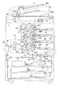
先ず、本発明を用いる画像形成装置の一例を図1の構成図に基づいて説明する。 First, an example of an image forming apparatus using the present invention will be described with reference to the block diagram of FIG.
本画像形成装置は画像形成装置本体GHと画像読取装置YSとから構成される。 The image forming apparatus includes an image forming apparatus main body GH and an image reading apparatus YS.
画像形成装置本体GHは、タンデム型カラー画像形成装置と称せられるもので、複数組の画像形成部10Y,10M,10C,10K、ベルト状の中間転写ベルト5、給紙搬送手段及び定着装置8等からなる。
The image forming apparatus main body GH is called a tandem type color image forming apparatus. A plurality of sets of
画像形成装置本体GHの上部には、自動原稿送り装置YS1と原稿画像走査露光装置YS2から成る画像読取装置YSが設置されている。自動原稿送り装置YS1の原稿台に載置された原稿dは搬送手段により搬送され、原稿画像走査露光装置YS2の光学系により原稿の片面又は両面の画像が走査露光され、ラインイメージセンサCCDに読み込まれる。 An image reading device YS including an automatic document feeder YS1 and a document image scanning exposure device YS2 is installed on the upper portion of the image forming apparatus main body GH. The document d placed on the document table of the automatic document feeder YS1 is transported by a transport means, and an image on one or both sides of the document is scanned and exposed by the optical system of the document image scanning exposure device YS2, and is read into the line image sensor CCD. It is.
ラインイメージセンサCCDにより光電変換されて形成された信号は、画像処理部において、アナログ処理、A/D変換、シェーディング補正、画像圧縮処理等が行われた後、露光手段3Y,3M,3C,3Kに送られる。 A signal formed by photoelectric conversion by the line image sensor CCD is subjected to analog processing, A / D conversion, shading correction, image compression processing, and the like in an image processing unit, and then exposure means 3Y, 3M, 3C, 3K. Sent to.
イエロー(Y)色の画像を形成する画像形成部10Yは、感光体ドラム1Yの周囲に帯電手段2Y、露光手段3Y、現像手段4Y及びクリーニング手段7Yを配置している。マゼンタ(M)色の画像を形成する画像形成部10Mは、感光体ドラム1Mの周囲に帯電手段2M、露光手段3M、現像手段4M及びクリーニング手段7Mを配置している。シアン(C)色の画像を形成する画像形成部10Cは、感光体ドラム1Cの周囲に帯電手段2C、露光手段3C、現像手段4C及びクリーニング手段7Cを配置している。黒(K)色の画像を形成する画像形成部10Kは、感光体ドラム1Kの周囲に帯電手段2K、露光手段3K、現像手段4K及びクリーニング手段7Kを配置している。そして、帯電手段2Yと露光手段3Y、帯電手段2Mと露光手段3M、帯電手段2Cと露光装置3C、及び帯電手段2Kと露光装置3Kは、潜像形成手段を構成する。
In the
なお、現像手段4Y,4M,4C,4Kは、イエロー(Y)、マゼンタ(M)、シアン(C)及び黒(K)の小粒径のトナーとキャリアからなる2成分現像剤を内包する。トナーは発色剤となる顔料若しくは染料と、定着後に定着部材からのトナーの剥離を助けるワックスと、これらを保持するバインダー樹脂とからなる。
The developing
中間転写ベルト5は、複数のローラにより巻回され、回動可能に支持されている。 The intermediate transfer belt 5 is wound around a plurality of rollers and is rotatably supported.
定着装置8は、加熱された定着ベルト81と加圧ローラ83との間に形成されたニップ部で記録紙(記録材)Pのトナー像を加熱・加圧して定着する。
The fixing
かくして、画像形成部10Y,10M,10C,10Kより形成された各色の画像は、回動する中間転写ベルト5に転写手段6Y,6M,6C,6Kにより逐次転写されて(1次転写)、カラー画像合成されたトナー像が形成される。給紙カセット20内に収容された記録紙Pは、給紙手段21により給紙され、給紙ローラ22A,22B,22C,22D,レジストローラ23等を経て、転写手段6Aに搬送され、記録紙Pにカラー画像が転写される(2次転写)。カラー画像が転写された記録紙Pは定着装置8において加熱・加圧され、記録紙Pのカラートナー像が定着される。その後、排紙ローラ24に挟持されて機外の排紙トレイ25に載置される。
Thus, each color image formed by the
一方、転写手段6Aにより記録紙Pにカラー画像を転写した後、記録紙Pを曲率分離した中間転写ベルト5は、クリーニング手段7Aにより残留トナーが除去される。
On the other hand, after the color image is transferred to the recording paper P by the
なお、以上はカラー画像を形成する画像形成装置であったが、モノクロ画像を形成する画像形成装置であってもよいし、中間転写ベルトを用いても用いなくてもよい。 The image forming apparatus for forming a color image has been described above. However, an image forming apparatus for forming a monochrome image may be used, or an intermediate transfer belt may or may not be used.
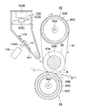
次に、定着装置8について、図2の断面図に基づいて説明する。
Next, the fixing
定着ベルト81は、無端状に形成され、例えば、導電性のPI(ポリイミド)から成る厚さ70μmの基体の外周面を、耐熱性のシリコンゴム(硬度JIS−A30°)から成る厚さ220μmの弾性層で被覆し、更に、耐熱性樹脂であるPFA(パーフルオロアルコキシ)から成る厚さ30μmのチューブで被覆している。なお、内径寸法は例えば80mmである。
The fixing
加熱ローラ82は、定着ベルト81を加熱するハロゲンランプ82Aを内蔵し、例えば、アルミニウム等から形成された肉厚3mmの円筒状の芯金82Bの外周面を、厚さ30μmのPFAでコーティングした樹脂層82Cで被覆している。なお、外径寸法は例えば52mmである。
The
また、ハロゲンヒータ82Aとしては、異なった紙幅に対応するため例えば930Wと600Wの部分を設けて軸方向に異なる発熱分布にしてある。
Further, as the
定着ローラ83は、鉄等の金属から形成された中実の芯金83Aを、耐熱性のソリッドゴムであるシリコンゴム(硬度JIS−A10°)から成る厚さ7.5mmの弾性層83Bで被覆している。なお、外径寸法は例えば40mmである。また、シリコーンゴムに代えてフッ素ゴムを用いてもよい。
The fixing
加圧ローラ84は、画像出力装置への電源投入直後の昇温時間を短縮するためのハロゲンランプ84Aを内蔵し、アルミニウム等から形成された肉厚3mmの円筒状の芯金84Bの外周面を、耐熱性のシリコンゴム(硬度JIS−A20°)から成る厚さ2mmの弾性層94Cで被覆し、更に、厚さ30μmのPFAチューブの樹脂層84Dで被覆している。なお、外径寸法は例えば50mmである。
The
また、ハロゲンヒータ84Aは例えば700Wである。
The
そして、不図示の付勢手段により、加圧ローラ84が定着ベルト81を定着ローラ83に圧接させている。
The
なお、樹脂層82C,84DをPTFE(ポリテトラフルオロエチレン)のチューブの被覆やコーティング加工によって形成してもよい。 The resin layers 82C and 84D may be formed by covering or coating PTFE (polytetrafluoroethylene) tubes.
また、定着ベルト81を加熱する加熱手段として、どのような加熱手段を用いてもよく、例えば励磁コイルを用いた誘導加熱発熱体を用いてもよい。また、加熱手段は、必ずしも加熱ローラ82等の中に配置されていなくてもよく、どこに配置されていてもよい。
Further, any heating means may be used as the heating means for heating the fixing
また、定着ベルトを押圧するテンションローラを設けた定着装置であってもよい。 Further, a fixing device provided with a tension roller for pressing the fixing belt may be used.
以上の構成において、不図示の駆動手段によって定着ローラ83を時計方向に回転させると、定着ベルト81及び加熱ローラ82も時計方向に回転し、加圧ローラ84は反時計方向に回転する。なお、加圧ローラ84を駆動してもよい。加熱ローラ82はハロゲンヒータ82Aにより加熱され、加熱ローラ82に当接する定着ベルト81も加熱される。そして、不図示の付勢手段によって加圧ローラ84が定着ローラ83の方向に付勢されているので、定着ローラ83に巻回された定着ベルト81と加圧ローラ84との間のニップ部Nで、給紙された記録紙Pが加熱・加圧されて、記録紙P上のトナー像が定着される。
In the above configuration, when the fixing
以上の如き定着装置8において、定着された記録材Pがニップ部Nから排紙された後に定着ベルト81に付着して巻き付くとジャムが発生する虞があるので、記録材Pを定着ベルト81から確実に分離させる必要がある。
In the
そこで、本定着装置8においては、この分離手段としてニップ部Nの出口側近傍にエアノズル101を設けている。エアノズル101は、略鉛直方向に送風するように配置されたファンモータ102により送風された空気を吐出するものである。エアノズル101は先端に行くに従って断面積が小さく形成されている。そして、エアノズル101の先端は定着ローラ83に張架された定着ベルト81の接線方向に向いている。このようにして、ニップ部Nを抜け出した記録紙Pに空気を連続して吹き付けて、定着ベルト81に付着しないようにしている。また、エアノズル101は耐熱樹脂等から形成されている。
Therefore, in the
ファンモータ102はファン102A、ファン102Aを回転駆動するモータ102B、及びモータ102Bに導通して外部電源から不図示のスイッチを経由して入力した電力をモータ102Bに送電すると共に、モータ102Bを制御する電子部品が実装されたファン制御部としてのプリント回路板102C等から構成される。
The
一例として、ファンモータ102は定格24VDC、静圧125Paのものを用いる。
As an example, the
また、ファン102Aは、軸流ファン、シロッコファン、クロスフローファン、若しくはブロア等でもよく、要は定着ベルト81から記録紙Pを分離可能な風圧や風量を有していればよい。
The
ここで、記録紙Pにプリントを行わないとき、即ち非定着時には分離のための送風を行う必要がないので、ファンモータ102の回転を停止することが望ましい。この際に、定着ベルト81により加熱されて水蒸気を有する空気が上昇するので、一部の空気はエアノズル101の流路を逆に通ってファンモータ102に達する。ファンモータ102のプリント回路板102Cに水蒸気を有する空気が当たり結露すると、電子部品がショートして破損し、ファンモータ102が作動しなくなることがある。
Here, when printing is not performed on the recording paper P, that is, at the time of non-fixing, it is not necessary to perform blowing for separation, so it is desirable to stop the rotation of the
そこで、エアノズル101の流路に耐熱樹脂等から形成された開閉弁111を設け、定着時には開閉弁111を退避させてエアノズル101の流路を開放する。一方、非定着時には開閉弁111を回動してエアノズル101の流路を閉鎖し、定着ベルト81により加熱された空気がファンモータ102に到達することを阻止している。
Therefore, an opening /
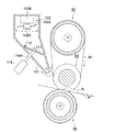
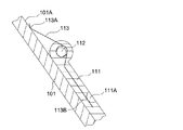
以下に、開閉弁111を開閉作動させて定着ベルト81により加熱された空気がファンモータ102に到達することを阻止する加熱空気阻止手段について図2〜5を参照して説明する。図2は開閉弁111を開放状態にした定着装置の断面図、図3は開閉弁111を閉鎖状態にした定着装置の断面図、図4は開閉弁111の部分拡大図、図5は開閉弁111を作動させるブロック図である。
Hereinafter, heated air blocking means for blocking the air heated by the fixing
図2,3に示す如く、開閉弁111は支軸112に支持され、支軸112を中心に回動自在に構成されている。
As shown in FIGS. 2 and 3, the on-off
図4に示す如く、支軸112にはねじりコイルばね113が係着していて、ねじりコイルばね113の一端113Aはエアノズル101の内壁101Aに当接し、ねじりコイルばね113の他端113Bは開閉弁111に設けたボス111Aに当接している。従って、ねじりコイルばね113は図2〜4に示す開閉弁111を反時計方向に付勢している。即ち、開閉弁111はエアノズル101の流路を閉鎖する方向に付勢されている。
As shown in FIG. 4, a
なお、開閉弁111を付勢するための付勢部材としては、ねじりコイルばねに限定されるものではなく、引張コイルばねや圧縮コイルばねを用いてもよい。
The biasing member for biasing the on-off
エアノズル101の外部にはソレノイド114が設けられ、ソレノイド114のプランジャ114Aがエアノズル101の側壁を貫通し、開閉弁111と係合している。そして、定着時には、ソレノイド114に通電すると、図2の如くプランジャ114Aの後端がソレノイド114の中に後退するので、開閉弁111は引き込まれて時計方向に回動し、開放状態になる。従って、ファンモータ102に送風された空気がニップ部Nの出口側に吐出する。
A
一方、非定着時にソレノイド114に通電を行わなければ、図3の如くプランジャ114Aはソレノイド114の内部に設けた不図示のバネにより突出するので、開閉弁111はねじりコイルばね113によって反時計方向に回動し、先端がエアノズル101の内壁に当接してエアノズル101の流路を閉鎖する。この結果、定着ベルト81により加熱された空気がファンモータ102に到達することがなく、プリント回路板102Cに実装された電子部品が破損することがない。なお、定着ベルト81により加熱された空気はエアノズル101の周囲を通って上昇することになる。
On the other hand, if the
また、定着時のみにソレノイド114に通電すればよく、非定着時にはソレノイド114に通電する必要がないので、無駄な電力消耗がない。更に、画像形成装置の電源が何らかの原因によりオフになったときにはエアノズル101の流路が閉鎖されるので、ファンモータ102は確実に保護される。
Further, it is sufficient to energize the
なお、ねじりコイルばね113とソレノイド114が特許請求の範囲に記載の開閉弁駆動手段に相当する。
The
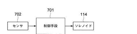
次に、ソレノイド114の制御に関し、図5のブロック図に基づいて説明する。
Next, control of the
図1に示す如くレジストローラ23の上流側にフォトセンサ等から成るセンサ702を配置する。記録紙Pが給紙されたことをセンサ702が検知すると、CPU等から成る制御手段701はソレノイド114をオンにし、開閉弁111を開放状態にする。記録紙Pが給紙されたことをセンサ702が検知した後、所定時間経過してもセンサ702が再び検知しなければ、記録紙Pの給紙が行われないので、制御手段701はソレノイド114をオフにして開閉弁111を閉鎖状態にする。
As shown in FIG. 1, a
また、ファンモータ102の作動に関しては、モータ102Bは通電してから最大回転数になるまでタイムラグがあるので、記録紙Pが給紙手段21により給紙されたことを検知した後、モータ102Bを回転開始させることが望ましい。
Regarding the operation of the
ここで、図3の如く開閉弁111を閉鎖したときは、定着ベルト81により加熱された空気はエアノズル101の周囲を上昇する。この際に、該空気がエアノズル101の中の開閉弁111の手前にも入り込んで停滞する。そこで、開閉弁111より吐出口側に位置するエアノズル101の側壁に排気口を設ければ、停滞した空気は排気される。
Here, when the on-off
次に、加熱空気阻止手段に関し、異なる実施の形態を図6〜10を参照して説明する。 Next, different embodiments of the heated air blocking means will be described with reference to FIGS.
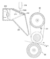
図6においては、ファンモータ202は水平方向に送風するように配置されており、エアノズル201の流路に支軸212を中心に回動する開閉弁211が配置されている。定着時にソレノイド214に通電すると、プランジャ214Aはソレノイド214の中に潜り込むので、金属等の比重の大きい材料で形成された開閉弁211を引き上げ、支軸212を中心に開閉弁121を時計方向に回動させ、実線で示す開放状態にする。非定着時にソレノイド214に通電しなければ、プランジャ214Aは下方に伸びるので、開閉弁211は支軸212を中心に自重で反時計方向に回動し、二点鎖線で示す閉鎖状態になる。従って、本構成においては前述の如きねじりコイルばね113等の付勢部材は不要になる。
In FIG. 6, the
この場合は、ソレノイド214と開閉弁211の自重が開閉弁駆動手段に相当する。
In this case, the weights of the
また、以上の形態において、開閉弁111,211を駆動するアクチュエータとしては、ソレノイド114,214に限定されるものではなく、例えばモータを用いてもよい。
In the above embodiment, the actuator for driving the on-off
図7においても、ファンモータ302は水平方向に送風するように配置されており、エアノズル301の中に鉛直方向に摺動する開閉弁311が配置されている。そして、非定着時に不図示のアクチュエータに通電しないときには、開閉弁311は自重で下方に移動し、閉鎖状態になる。一方、定着時にアクチュエータに通電すると、開閉弁311は上昇し、開放状態になる。
Also in FIG. 7, the
この場合は、開閉弁311を駆動するアクチュエータとしてモータが好ましく、モータで回転するカムで開閉弁311を移動させたり、モータで回転するピニオンより開閉弁311に設けたラックを移動させたりすればよい。
In this case, a motor is preferable as an actuator for driving the on-off
この場合は、アクチュエータと開閉弁311の自重が開閉弁駆動手段に相当する。
In this case, the weight of the actuator and the on-off
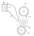
図8においては、ファンモータ402を内蔵する筐体404がエアノズル401の上方に配置されている。ファンモータ402からエアノズル401に送風するので、エアノズル401の上部における筐体404との当接部には開口した開口部401Aが形成されている。
In FIG. 8, a
筐体404は支軸405を中心に回動可能に構成されている。定着時には筐体404は二点鎖線で示す姿勢になり、ファンモータ402は開口部401Aを通してエアノズル401に送風する。一方、非定着時には筐体404はファンモータ402と共に実線で示す姿勢に回動して退避する。このとき、開口部401Aは大きく露出するので、定着ベルト81により加熱された空気が上昇すると、空気はこの開口部401Aから上方に逃げる。従って、側方に退避したファンモータ402に影響が出ることはない。
The
なお、筐体404に支軸405を一体的に装着し、不図示のモータにより支軸405を回転駆動することが望ましい。
It is desirable that the
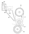
図9においても、ファンモータ502を内蔵する筐体504がエアノズル501の上方に配置されており、ファンモータ502からエアノズル501に送風するので、エアノズル501の上部における筐体504との当接部には開口した開口部501Aが形成されている。
Also in FIG. 9, the
筐体504はエアノズル501の上方を水平方向に摺動するように構成されている。定着時には筐体504は二点鎖線で示す位置になり、ファンモータ502は開口部501Aを通してエアノズル501に送風する。一方、非定着時には筐体504はファンモータ502と共に実線で示す姿勢に移動して退避する。このとき、開口部501Aは大きく露出するので、定着ベルト81により加熱された空気が上昇すると、空気はこの開口部501Aから上方に逃げるので、側方に退避したファンモータ502に影響が出ることはない。
The
なお、筐体504の移動方法としては、筐体504にラックを設け、モータで回転するピニオンでラックを移動させることが望ましい。
As a method for moving the
図8、9においては、開口部401A,501Aとファンモータ402,502を移動させる手段が加熱空気阻止手段に相当する。
8 and 9, the means for moving the
更に、移動する開閉弁を設けずに、エアノズルを通って上昇した空気がファンモータに当たらないように構成することも可能であり、このような構成を図10に示す。 Furthermore, it is possible to configure so that the air that has risen through the air nozzle does not hit the fan motor without providing a moving on-off valve, and such a configuration is shown in FIG.
図10においては、エアノズル601は屈曲して形成され、ファンモータ602は水平方向から送風するように配置されている。従って、ファンモータ602から送風された空気はエアノズル601の内部で方向を変えてエアノズル601から吐出する。また、エアノズル601には、ファンモータ602から離れた位置の上壁に大きく開口された開口部601Aが設けられている。
In FIG. 10, the
定着時にはファンモータ602からエアノズル601を介して前述と同様に送風するが、開口部601Aは空気の流路の側方であるので、空気が開口部601Aから吐出することは殆どない。一方、非定着時には定着ベルト81により加熱された空気がエアノズル601を通って上昇したときに、そのまま開口部601Aから上方に逃げるので、側方に位置するファンモータ502に影響が出ることはない。
At the time of fixing, air is blown from the
これにより、開閉弁と共に開閉弁を駆動する駆動手段を設ける必要がないので、簡素な構成になり、安価に形成することができる。 Thereby, since it is not necessary to provide a driving means for driving the on-off valve together with the on-off valve, the structure is simple and can be formed at a low cost.
また、この場合は、屈曲して形成され、ファンモータ602より離れた位置の上壁に開口部601Aを有するエアノズル601が加熱空気阻止手段に相当する。
Further, in this case, the
以上の各実施の形態において、非プリント時には無駄な電力消耗が生じないようにファンモータを完全に停止するのが望ましい。しかし、ファンモータは通電してから最大回転数になるまでにタイムラグがあるので、プリント時に対する応答性を確保するため、非プリント時にもファンモータを低速で回転し続けるようにしてもよい。 In each of the above-described embodiments, it is desirable to completely stop the fan motor so that unnecessary power consumption does not occur during non-printing. However, since there is a time lag until the maximum rotation speed is reached after the fan motor is energized, the fan motor may continue to rotate at a low speed even during non-printing in order to ensure responsiveness during printing.
例えば、定格24VDCのモータを用いたときは、非定着時には印加電圧を約8VDCにして、モータを低速で回転させてもよい。 For example, when a motor with a rating of 24 VDC is used, the applied voltage may be about 8 VDC during non-fixing, and the motor may be rotated at a low speed.
また、非定着時には印加電圧を24VDCに維持したままオン時間を1秒にしオフ時間を2秒にしたサイクルを繰り返してもよい。 Further, at the time of non-fixing, a cycle in which the on time is 1 second and the off time is 2 seconds may be repeated while maintaining the applied voltage at 24 VDC.
また、モータがPWM(パルス幅変調)制御に対応するものであれば、非定着時にはオン時間を1msにしオフ時間を2msにしたサイクルを繰り返してもよい。 If the motor supports PWM (pulse width modulation) control, a cycle in which the on time is set to 1 ms and the off time is set to 2 ms may be repeated during non-fixing.
なお、以上の各実施の形態においては、加熱空気阻止手段を備えたベルト定着装置について説明したが、加熱空気阻止手段を同様に熱ローラ定着装置に備えてもよい。 In each of the above embodiments, the belt fixing device provided with the heated air blocking means has been described. However, the heated air blocking device may also be provided in the heat roller fixing device.
8 定着装置
81 定着ベルト
101,201,301,401,501,601 エアノズル
102,202,302,402,502,602 ファンモータ
102A ファン
102B モータ
102C プリント回路板
111,211,311 開閉弁
113 ねじりコイルばね
114,214 ソレノイド
114A,214A プランジャ
401A,501A,601A 開口部
404,504 筐体
701 制御手段
702 センサ
N ニップ部
P 記録紙
DESCRIPTION OF
Claims (8)
ファン、該ファンを回転させるモータ及び該モータを制御するファン制御部を有するファンモータと、
記録材の定着時に、前記ファンモータによって送風された空気を前記ニップ部の出口部近傍に吹き付けるエアノズルと、
記録材の非定着時に、前記定着部材にて加熱された空気が前記エアノズルを通って前記ファンモータに到達することを阻止する加熱空気阻止手段と、
を備えたことを特徴とする定着装置。 In a fixing device that fixes a toner image of a recording material at a nip formed by a heated fixing member and a pressure member that pressurizes the fixing member.
A fan motor having a fan, a motor for rotating the fan, and a fan control unit for controlling the motor;
An air nozzle that blows air blown by the fan motor to the vicinity of the exit of the nip when fixing the recording material;
Heated air blocking means for blocking air heated by the fixing member from reaching the fan motor through the air nozzle when the recording material is not fixed;
A fixing device comprising:
前記加熱空気阻止手段は、前記開口部と、記録材の非定着時に前記ファンモータを退避させ前記開口部を露出させる手段と、であることを特徴とする請求項1に記載の定着装置。 The air nozzle has an opening at the top for allowing the air blown from the fan motor to pass through,
The fixing device according to claim 1, wherein the heating air blocking unit includes the opening and a unit that retracts the fan motor to expose the opening when the recording material is not fixed.
Priority Applications (1)
| Application Number | Priority Date | Filing Date | Title |
|---|---|---|---|
| JP2010100688A JP5577818B2 (en) | 2010-04-26 | 2010-04-26 | Fixing apparatus and image forming apparatus |
Applications Claiming Priority (1)
| Application Number | Priority Date | Filing Date | Title |
|---|---|---|---|
| JP2010100688A JP5577818B2 (en) | 2010-04-26 | 2010-04-26 | Fixing apparatus and image forming apparatus |
Publications (2)
| Publication Number | Publication Date |
|---|---|
| JP2011232425A true JP2011232425A (en) | 2011-11-17 |
| JP5577818B2 JP5577818B2 (en) | 2014-08-27 |
Family
ID=45321812
Family Applications (1)
| Application Number | Title | Priority Date | Filing Date |
|---|---|---|---|
| JP2010100688A Expired - Fee Related JP5577818B2 (en) | 2010-04-26 | 2010-04-26 | Fixing apparatus and image forming apparatus |
Country Status (1)
| Country | Link |
|---|---|
| JP (1) | JP5577818B2 (en) |
Citations (2)
| Publication number | Priority date | Publication date | Assignee | Title |
|---|---|---|---|---|
| JPH0854801A (en) * | 1994-08-10 | 1996-02-27 | Toshiba Corp | Fixing device |
| JP2001242964A (en) * | 2000-02-28 | 2001-09-07 | Hitachi Ltd | Cooling method, cooling device, and information processing device |
-
2010
- 2010-04-26 JP JP2010100688A patent/JP5577818B2/en not_active Expired - Fee Related
Patent Citations (2)
| Publication number | Priority date | Publication date | Assignee | Title |
|---|---|---|---|---|
| JPH0854801A (en) * | 1994-08-10 | 1996-02-27 | Toshiba Corp | Fixing device |
| JP2001242964A (en) * | 2000-02-28 | 2001-09-07 | Hitachi Ltd | Cooling method, cooling device, and information processing device |
Also Published As
| Publication number | Publication date |
|---|---|
| JP5577818B2 (en) | 2014-08-27 |
Similar Documents
| Publication | Publication Date | Title |
|---|---|---|
| JP5100228B2 (en) | Image heating device | |
| US7536145B2 (en) | Image heating apparatus | |
| JP5321341B2 (en) | Fixing apparatus and image forming apparatus | |
| JP5359764B2 (en) | Fixing apparatus and image forming apparatus | |
| US20070230983A1 (en) | Image heating apparatus and image forming apparatus | |
| US7433625B2 (en) | Image heating apparatus | |
| US7542692B2 (en) | Image forming apparatus with detecting members for determining when set width is wrong | |
| JP2008139817A (en) | Fixing apparatus and image forming apparatus | |
| JP5573612B2 (en) | Fixing apparatus and image forming apparatus | |
| JP5577834B2 (en) | Fixing apparatus and image forming apparatus | |
| JP5454002B2 (en) | Fixing apparatus and image forming apparatus | |
| JP5577819B2 (en) | Fixing apparatus and image forming apparatus | |
| JP5661302B2 (en) | Fixing apparatus and image forming apparatus | |
| JP2011232427A (en) | Fixing device and image forming apparatus | |
| JP2004287317A (en) | Image forming apparatus | |
| US9141056B2 (en) | Fixing device and image forming apparatus incorporating same | |
| JP2011242429A (en) | Fixing device and image forming apparatus | |
| JP5577818B2 (en) | Fixing apparatus and image forming apparatus | |
| JP2012088355A (en) | Fixing device and image forming apparatus | |
| JP2011257670A (en) | Image forming apparatus | |
| JP5754300B2 (en) | Fixing apparatus and image forming apparatus | |
| JP2006227486A (en) | Image forming apparatus | |
| JP2006235573A (en) | Image forming apparatus | |
| JP5359423B2 (en) | Fixing apparatus and image forming apparatus provided with the fixing apparatus | |
| JP5585459B2 (en) | Fixing apparatus and image forming apparatus |
Legal Events
| Date | Code | Title | Description |
|---|---|---|---|
| A621 | Written request for application examination |
Free format text: JAPANESE INTERMEDIATE CODE: A621 Effective date: 20121019 |
|
| RD02 | Notification of acceptance of power of attorney |
Free format text: JAPANESE INTERMEDIATE CODE: A7422 Effective date: 20130215 |
|
| A711 | Notification of change in applicant |
Free format text: JAPANESE INTERMEDIATE CODE: A712 Effective date: 20130416 |
|
| A977 | Report on retrieval |
Free format text: JAPANESE INTERMEDIATE CODE: A971007 Effective date: 20130805 |
|
| A131 | Notification of reasons for refusal |
Free format text: JAPANESE INTERMEDIATE CODE: A131 Effective date: 20130820 |
|
| A521 | Written amendment |
Free format text: JAPANESE INTERMEDIATE CODE: A523 Effective date: 20131018 |
|
| TRDD | Decision of grant or rejection written | ||
| A01 | Written decision to grant a patent or to grant a registration (utility model) |
Free format text: JAPANESE INTERMEDIATE CODE: A01 Effective date: 20140610 |
|
| A61 | First payment of annual fees (during grant procedure) |
Free format text: JAPANESE INTERMEDIATE CODE: A61 Effective date: 20140623 |
|
| R150 | Certificate of patent or registration of utility model |
Ref document number: 5577818 Country of ref document: JP Free format text: JAPANESE INTERMEDIATE CODE: R150 |
|
| LAPS | Cancellation because of no payment of annual fees |