JP2012001237A - Preventing corrugated cardboard from wounding hand - Google Patents
Preventing corrugated cardboard from wounding hand Download PDFInfo
- Publication number
- JP2012001237A JP2012001237A JP2010137435A JP2010137435A JP2012001237A JP 2012001237 A JP2012001237 A JP 2012001237A JP 2010137435 A JP2010137435 A JP 2010137435A JP 2010137435 A JP2010137435 A JP 2010137435A JP 2012001237 A JP2012001237 A JP 2012001237A
- Authority
- JP
- Japan
- Prior art keywords
- trunk
- edge
- cardboard
- ruled line
- branch
- Prior art date
- Legal status (The legal status is an assumption and is not a legal conclusion. Google has not performed a legal analysis and makes no representation as to the accuracy of the status listed.)
- Pending
Links
- 238000004080 punching Methods 0.000 claims abstract description 16
- 238000003825 pressing Methods 0.000 claims description 36
- 238000005520 cutting process Methods 0.000 claims description 21
- 230000002265 prevention Effects 0.000 claims description 8
- 238000004519 manufacturing process Methods 0.000 claims description 5
- 239000011096 corrugated fiberboard Substances 0.000 abstract 6
- 230000003449 preventive effect Effects 0.000 abstract 2
- 230000015556 catabolic process Effects 0.000 abstract 1
- 238000006731 degradation reaction Methods 0.000 abstract 1
- 230000000694 effects Effects 0.000 description 7
- 239000000758 substrate Substances 0.000 description 6
- 239000000123 paper Substances 0.000 description 4
- 238000007789 sealing Methods 0.000 description 4
- 238000002513 implantation Methods 0.000 description 2
- 238000000034 method Methods 0.000 description 2
- 229920001342 Bakelite® Polymers 0.000 description 1
- 229910001369 Brass Inorganic materials 0.000 description 1
- 239000004831 Hot glue Substances 0.000 description 1
- 239000000853 adhesive Substances 0.000 description 1
- 230000001070 adhesive effect Effects 0.000 description 1
- 239000004637 bakelite Substances 0.000 description 1
- 235000013405 beer Nutrition 0.000 description 1
- 238000005452 bending Methods 0.000 description 1
- 235000013361 beverage Nutrition 0.000 description 1
- 239000010951 brass Substances 0.000 description 1
- 230000006835 compression Effects 0.000 description 1
- 238000007906 compression Methods 0.000 description 1
- 238000000605 extraction Methods 0.000 description 1
- 239000000463 material Substances 0.000 description 1
- 239000000155 melt Substances 0.000 description 1
- 238000004806 packaging method and process Methods 0.000 description 1
- 239000011120 plywood Substances 0.000 description 1
- 229910001220 stainless steel Inorganic materials 0.000 description 1
- 239000010935 stainless steel Substances 0.000 description 1
Images
Landscapes
- Cartons (AREA)
- Making Paper Articles (AREA)
Abstract
Description
この発明は、段ボールの端縁部における手切れを防止する構造、その構造を適用したカートン及びブランクを打ち抜く抜型に関するものである。 The present invention relates to a structure for preventing hand-cutting at an edge of a corrugated cardboard, and a die for punching a carton and a blank to which the structure is applied.
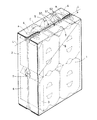
例えば、ビール等の飲料缶を包装する際には、図9に示すように、各一対の側板1,2を各対それぞれが対向するように継代片3を介して筒状に連設し、集積した缶C入りの複数個のパックをその筒状の側板1,2により包み込んで、各側板2から延びる内フラップ4と、各側板1から延びる外フラップ5とを順次内側へ折り曲げ、ホットメルト接着剤により接着部aで貼り合わせて端面を封緘するラップラウンド式の段ボール製カートンが使用されている。
For example, when packaging beverage cans such as beer, as shown in FIG. 9, a pair of
このようなカートンには、横置きにした状態でトレー状に分割して開封できるように、側板2から内フラップ4へかけて、カットテープ等の引裂帯6が設けられ、その切出部7が側板2の中央部に切込により形成されている。
In such a carton, a
ところで、上記のようなカートンを家庭で開封する際には、缶Cを必要な分だけ取り出して、残存した分を嵩張ることなく保管しておくため、縦置きにした状態で、上方となった外フラップ5と内フラップ4とが重なる端面から開封する場合が多く、その際、外側の外フラップ5を内側の内フラップ4から引き剥がそうとして、外フラップ5の端縁に手を掛けると、段ボールの鋭い切断縁に手が当たって、手が切れることがある。
By the way, when opening the carton as described above, the can C is taken out as much as necessary, and the remaining portion is stored without being bulky. In many cases, the
このため、下記特許文献1において、図10に示すように、外フラップ5の端縁部に平行に基準線Lを設定し、その基準線Lに直交する複数本の押罫線51と、これに交差する複数の連続した押罫線52とを格子状に入れて、段ボールの端縁から離れた位置まで押潰部50を形成した段ボールカートンが提案されている。
For this reason, in
この特許文献1に記載の発明は、段ボールを構成する中しん紙が波状に段形成されていることから厚みがあって剛性を有する外フラップ5の端縁部を、押潰部50で中しん紙の段を押し潰すことにより軟化させ、開封時における手の当たりを柔らかくすることを意図している。なお、一方の側板1に入れられた斜折線8は、開封時に折り曲げて開口部を拡大するためのものである。
In the invention described in
しかしながら、上記のような格子状の押潰部を設けると、段ボールの圧縮部位が広範囲に及ぶことから、封緘時の強度が若干低下するおそれがあり、また、段ボールの端縁から離れた押罫線を省略すると、手切れ防止効果が十分に得られないという問題があった。 However, if the grid-like crushing portion as described above is provided, the compression portion of the cardboard extends over a wide range, so that the strength at the time of sealing may be slightly reduced, and the ruled line separated from the edge of the cardboard If is omitted, there is a problem that the effect of preventing hand-cutting cannot be sufficiently obtained.
また、このような格子状の押潰部を形成する抜型では、押罫線を入れるため基板に植え込む押圧片等の部品点数が多くなり、基板への植込溝の形成にも多くの工程を要することから、製作コストが高くなり、さらに、格子状の押圧片の全てを対向する面板の溝へ嵌合させる必要があることから、抜型及び面板の加工や、これらの打抜機への装着に厳密な精度が要求されるという問題があった。 In addition, in the punching die that forms such a grid-like crushing portion, the number of parts such as pressing pieces to be implanted in the substrate increases in order to insert ruled lines, and many steps are required for forming the implantation groove in the substrate. Therefore, the manufacturing cost is high, and furthermore, it is necessary to fit all of the lattice-shaped pressing pieces into the grooves of the facing face plate. Therefore, it is strictly applicable to die cutting and face plate processing and mounting to these punching machines. There is a problem that high accuracy is required.
そこで、この発明は、段ボールの強度を確保しつつ、手切れ防止効果を十分に得ること及び安価で過大な精度を要しない抜型で加工できるようにすることを課題とする。 Accordingly, an object of the present invention is to obtain a sufficient effect of preventing hand breakage while ensuring the strength of the cardboard, and to enable processing with a die cutting that is inexpensive and does not require excessive accuracy.
上記課題を解決するため、この発明は、段ボールの端縁に沿って押潰部を形成した段ボールの手切れ防止構造において、前記押潰部は、段ボールの端縁部に平行に設定した基準線と直交する方向の幹押罫線を、その先端を段ボールの端縁に近接させて複数本入れると共に、この幹押罫線に交差する枝押罫線を、幹押罫線ごとに断続的に、かつ、幹押罫線の後端側部分を除いて入れることにより、幹押罫線と枝押罫線とがT字状となるように形成したのである。 In order to solve the above-described problems, the present invention provides a cardboard hand break prevention structure in which a crushing portion is formed along an edge of the cardboard, wherein the crushing portion is a reference line set in parallel to the edge of the cardboard. A plurality of trunk ruled lines in a direction orthogonal to the edge of the corrugated cardboard are inserted, and branch ruled lines intersecting the trunk ruled lines are intermittently provided for each trunk ruled line. By inserting except for the rear end portion of the ruled line, the trunk ruled line and the branch ruled line are formed in a T shape.
また、前記段ボールの端縁を波状に切断し、その波状端縁の膨出部に対応して、幹押罫線を入れたのである。 Further, the edge of the corrugated cardboard was cut into a wave shape, and a trunk ruled line was inserted corresponding to the bulging portion of the waved edge.
さらに、前記段ボールの端縁と幹押罫線の先端との間に、その端縁に沿って連続的に縁押罫線を入れたのである。 Further, an edge ruled line is continuously provided along the edge between the edge of the cardboard and the tip of the trunk ruled line.
そして、一対の側板に内フラップを、他対の側板に外フラップをそれぞれ連設し、内フラップと外フラップとを貼り合わせて端面を封緘する段ボールカートンにおいて、少なくとも外フラップの端縁部に、この段ボールの手切れ防止構造を採用したのである。 And in the corrugated cardboard carton where the inner flap is connected to the pair of side plates, the outer flap is connected to the other pair of side plates, and the end surface is sealed by bonding the inner flap and the outer flap, at least at the edge of the outer flap, This structure for preventing cardboard hand breakage was adopted.
また、上記段ボールカートンを製造するため、その抜型において、段ボールの端縁を打ち抜く切刃に直交する方向に、幹押罫線を入れる複数枚の幹押圧片を並べて設け、枝押罫線を入れる枝押圧片を、幹押圧片ごとにこれに交差するように設けて、幹押圧片と枝押圧片とがT字状となるようにしたのである。 Also, in order to produce the corrugated cardboard carton, in the punching die, a plurality of stem pressing pieces for inserting the stem ruled lines are arranged in a direction perpendicular to the cutting edge for punching the edge of the cardboard, and the branch pressing for inserting the branch ruled lines A piece is provided so as to intersect with each of the stem pressing pieces so that the trunk pressing piece and the branch pressing piece have a T-shape.
このように、段ボールの端縁部に幹押罫線及び枝押罫線を入れて押潰部を形成すると、段ボールの端縁に手を掛けたとき、枝押罫線から幹押罫線へかけて段ボールが誘導されるように曲がるので、手の当たりが柔らかくなり、優れた手切れ防止効果が得られ、幹押罫線の後端側部分には交差する枝押罫線がないので、段ボールの強度低下が防止される。 In this way, when the crushing portion is formed by inserting the trunk ruled line and the branch ruled line at the edge part of the cardboard, when the hand is put on the edge of the cardboard, the cardboard is moved from the branch ruled line to the trunk ruled line. Because it bends as if guided, the touch of the hand is soft, and an excellent hand cut prevention effect is obtained, and there is no branch ruled line at the rear end side portion of the trunk ruled line, thus preventing a reduction in the strength of the cardboard Is done.
また、上記押潰部を形成するための抜型は、幹押罫線を入れる複数枚の幹押圧片ごとに枝押圧片を設けたので、押圧片等の点数が少なくなり、基板への植込工程を省力化して、安価に製作でき、その製作や打抜機への装着に過大な精度を要することもない。 In addition, since the die for forming the crushing portion is provided with a branch pressing piece for each of a plurality of stem pressing pieces for inserting a trunk ruled line, the number of pressing pieces and the like is reduced, and the step of implanting into the substrate is performed. Can be manufactured at low cost, and there is no need for excessive accuracy in manufacturing and mounting to a punching machine.
以下、この発明の実施形態を添付図面に基づいて説明する。 Embodiments of the present invention will be described below with reference to the accompanying drawings.
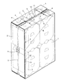
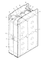
図1に示す段ボールカートンは、図9に示すものと同様に、各一対の側板1,2を各対それぞれが対向するように継代片3を介して筒状に連設し、集積した缶C入りの複数個のパックをその筒状の側板1,2により包み込んで、各側板2から延びる内フラップ4と、各側板1から延びる外フラップ5とを順次内側へ折り曲げ、ホットメルト接着剤により接着部aで貼り合わせて端面を封緘するラップラウンド式のものである。
The corrugated cardboard carton shown in FIG. 1 is a can in which a pair of
このカートンにおいては、側板2から内フラップ4へかけて、その幅方向の中央部に、横置き状態での開封に使用するカットテープ等の引裂帯6が設けられ、引裂帯6の切出部7が側板2の中央部に切込により形成されている。また、継代片3の外側に重なる側板1には、外フラップ5と内フラップ4とが重なる端面からの開封時に折り曲げて開口部を拡大する斜折線8が入れられている。
In this carton, from the
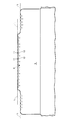
そして、図2に示すように、外フラップ5の端縁の中間部分及びこれより低く形成されている両肩部分では、段ボールの端縁が波状に切断され、この部分の外フラップ5の端縁部には、手切れ防止用の押潰部9が設けられている。押潰部9は、段ボールの波状端縁の頂点を結ぶ仮想的な基準線Lを設定し、この基準線Lと直交する方向に複数本等間隔に配列した直線状の幹押罫線10と、幹押罫線10に交差する枝押罫線11とをその端縁に近接して入れることにより形成されている。
Then, as shown in FIG. 2, at the middle portion of the edge of the
押潰部9において、幹押罫線10は、段ボールの波状端縁の膨出部の頂点位置に対応して入れられている。また、枝押罫線11は、幹押罫線10ごとに断続的に、かつ、段ボールの端縁寄りである幹押罫線10の先端を頂点として、幹押罫線10を中心に両側対称的に段ボールの端縁から遠ざかる方向へ広がるように傾斜し、幹押罫線10とでT字状となるように入れられており、段ボールの端縁から離れた幹押罫線10の後端側部分には入れられていない。
In the crushing
このような外フラップ5は、中しん紙が波状に段形成されている段ボールの構造から、厚みがあって剛性を有するものとなっているが、上記のように、押潰部9において、幹押罫線10と枝押罫線11とで中しん紙の段を押し潰すことにより、外フラップ5の端縁部が軟化する。
Such an
ここで、段ボールの端縁の波長は、指の滑りを効果的に防止するため、指の太さよりやや大きい程度からやや小さい程度までの任意の大きさとすればよい。また、段ボールの端縁には、微細な凹凸の滑り止め加工を施すことがあり、この場合、前述の波状加工を省略して、段ボールの端縁を直線状とし、その端縁を基準線Lとして設定してもよい。 Here, the wavelength of the edge of the corrugated cardboard may be set to an arbitrary size from slightly larger to slightly smaller than the thickness of the finger in order to effectively prevent finger slipping. Further, the edge of the cardboard may be subjected to anti-slip processing of fine irregularities. In this case, the corrugated processing described above is omitted, the edge of the cardboard is made straight, and the edge is set to the reference line L. May be set as
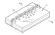
上記のような段ボールカートンは、シート状のブランクを組み立てて形成され、このブランクは、図3に示すような抜型21で段ボールシートを打ち抜いて製造される。
The corrugated cardboard carton as described above is formed by assembling a sheet-like blank, and this blank is manufactured by punching a corrugated cardboard sheet with a
抜型21では、基板となるベニヤ板に植え込まれて、外フラップ5の端縁となる輪郭を打ち抜く切刃22に直交する方向に、幹押罫線10を入れる直線状の幹押圧片23が等間隔に並べて設けられ、枝押罫線11を入れる枝押圧片24が幹押圧片23ごとにこれに交差するように同じ高さで設けられている。
In the
すなわち、切刃22、幹押圧片23及び枝押圧片24の形状や配置は、外フラップ5の端縁、幹押罫線10及び枝押罫線11の形状や配置に対応するものとなっている。
That is, the shapes and arrangements of the
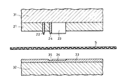
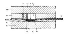
このような抜型21が装着される打抜機は、図4に示すように、互いに接離する上盤31及び下盤32を有し、上盤31に抜型21が取り付けられ、下盤32にステンレス製の面板33が取り付けられる。面板33の上面には、幹押圧片23及び枝押圧片24がそれぞれ挿入される溝34,35が形成されている。溝34,35の位置及び形状は、それぞれ幹押圧片23及び枝押圧片24の位置及び形状に対応している。
As shown in FIG. 4, the punching machine to which such a
なお、このように面板33に溝34,35を直接形成するのではなく、ベークライトや真鍮の板材に、幹押圧片23及び枝押圧片24が挿入される溝を形成した受部材を、面板33に突出するように貼り付けてもよい。
Instead of directly forming the
そして、この打抜機においては、段ボールシートSを抜型21と面板33の間に送り込み、図5に示すように、上盤31と下盤32とを接近させる。
In this punching machine, the corrugated cardboard sheet S is fed between the
これに伴い、段ボールシートSを、切刃22でその刃先が面板33に当接するように打ち抜いて外フラップ5の端縁となる輪郭を形成すると共に、幹押圧片23及び枝押圧片24で溝34,35に圧入するように押し潰し、外フラップ5の端縁部に幹押罫線10及び枝押罫線11を入れる。これにより、外フラップ5の端縁部に押潰部9を有するブランクが形成される。
Along with this, the corrugated cardboard sheet S is punched out with the
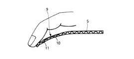
このような押潰部9を形成すると、図6に示すように、カートンの開封に際し、外フラップ5の端縁に手を掛けたとき、枝押罫線11から幹押罫線10へかけて外フラップ5が誘導されるように曲がるので、手の当たりが柔らかくなり、優れた手切れ防止効果が得られ、幹押罫線10の後端側部分には交差する枝押罫線11がないので、カートンの封緘時の強度低下が防止される。
When such a crushing
また、図1に示すように、外フラップ5の端縁部だけでなく、継代片3に重なる側板1の端縁部にも上記のような押潰部9を形成すると、持運び時の手切れを防止することができ、内フラップ4の端縁部にも上記のような押潰部9を形成すると、縦置き状態で開封して缶Cを取り出す場合に、内フラップ4の端縁での手切れを防止することができる。
Moreover, as shown in FIG. 1, when the above crushing
ところで、上記のような実施形態のほか、図7に示す第2実施形態のように、外フラップ5等の端縁部に押潰部9を形成するため、その端縁に直交する方向に直線状に延びる幹押罫線10の先端と後端との間で、両側に各2本の枝押罫線11を入れてもよい。この場合、枝押罫線11は、幹押罫線10を中心に両側へ対称的にその端縁へ近づく方向へ広がるように傾斜し、幹押罫線10とで変形T字状になるように形成されている。
By the way, in addition to the above-described embodiment, as in the second embodiment shown in FIG. 7, the crushing
また、図8に示す第3実施形態のように、幹押罫線10と枝押罫線11とを上記第2実施形態と同様に入れた上で、外フラップ5等の段ボールの端縁と幹押罫線10の先端部との間に、その端縁に沿って連続的に縁押罫線12を入れてもよい。このように縁押罫線12を入れると、段ボールの端縁付近が押し潰されて、さらに手の当たりが柔らかくなる。
Further, as in the third embodiment shown in FIG. 8, after the trunk ruled
なお、上記第1実施形態のように幹押罫線10と枝押罫線11とを入れたものにおいても、その幹押罫線10と枝押罫線11に加えて、段ボールの端縁に沿って連続的に縁押罫線12を入れると、手切れ防止効果が向上する。
Even in the case where the trunk ruled
ここで、上記第2実施形態及び第3実施形態に係る段ボールのブランクを形成するためには、第1実施形態に係る抜型21と同様に、それぞれの段ボールの端縁、幹押罫線10及び枝押罫線11に対応する切刃、幹押圧片及び枝押圧片を基板に植え込んだ抜型を製作すればよい。
Here, in order to form the corrugated cardboard blanks according to the second and third embodiments, as in the case of the die 21 according to the first embodiment, the edge of each corrugated cardboard, the trunk ruled
上記のような各実施形態に係る抜型は、幹押罫線10を入れる複数枚の幹押圧片23ごとに枝押圧片24を設けたので、特許文献1に記載の抜型に比較して、押圧片やその周辺のスポンジ等の点数が少なくなり、基板への植込工程を省力化して、安価に製作でき、その製作や打抜機への装着に過大な精度を要することもない。
In the die cutting according to each embodiment as described above, the
そして、上記各実施形態に係る手切れ防止構造の幹押罫線10は、その先端を段ボールの端縁に近接した位置に設ける方が手切れ防止効果を高めるために有効であり、また、幹押罫線10の長さは、あまり長いと段ボールの強度を低下させてしまうので、4mm〜10mmの範囲とするのがよい。
Further, it is more effective to provide the stem pressing ruled
また、段ボールの端縁が基準線Lに対して傾斜している場合、幹押罫線10は、段ボールの端縁に斜めに向かい、かつ、基準線Lに対して直交方向へ延びるものとすればよい。
Further, when the edge of the cardboard is inclined with respect to the reference line L, the trunk ruled
また、枝押罫線11は、直線状の幹押罫線10と交差してその両側へ延びることにより幹押罫線10とでT字状をなすものであれば、上記実施形態のような直線状のほか、弧状のような曲線状であってもよい。ただし、幹押罫線10を中心にして両側へ対称な形状であることが好ましい。
In addition, the branch ruled
さらに、枝押罫線11は、上記各実施形態のように、段ボールの端縁寄りである幹押罫線10の先端部付近に設ける方が手切れ防止効果が有効に得られ、後端部側に設けると、段ボールの強度を低下させるのみとなるおそれがある。
Further, as in the above-described embodiments, the branch ruled
なお、上記のような段ボールの手切れ防止構造は、ラップラウンド形式以外の段ボールカートンや段ボール製玩具等の構造物にも適用でき、その取扱時における安全性を向上させることができる。 The cardboard hand break prevention structure as described above can be applied to structures other than the wrap round type, such as a corrugated cardboard carton and a corrugated cardboard toy, and can improve safety during handling.
1,2 側板
3 継代片
4 内フラップ
5 外フラップ
6 引裂帯
7 切出部
8 斜折線
9 押潰部
10 幹押罫線
11 枝押罫線
12 縁押罫線
21 抜型
22 切刃
23 幹押圧片
24 枝押圧片
31 上盤
32 下盤
33 面板
34,35 溝
L 基準線
DESCRIPTION OF
Claims (5)
Priority Applications (1)
| Application Number | Priority Date | Filing Date | Title |
|---|---|---|---|
| JP2010137435A JP2012001237A (en) | 2010-06-16 | 2010-06-16 | Preventing corrugated cardboard from wounding hand |
Applications Claiming Priority (1)
| Application Number | Priority Date | Filing Date | Title |
|---|---|---|---|
| JP2010137435A JP2012001237A (en) | 2010-06-16 | 2010-06-16 | Preventing corrugated cardboard from wounding hand |
Publications (1)
| Publication Number | Publication Date |
|---|---|
| JP2012001237A true JP2012001237A (en) | 2012-01-05 |
Family
ID=45533686
Family Applications (1)
| Application Number | Title | Priority Date | Filing Date |
|---|---|---|---|
| JP2010137435A Pending JP2012001237A (en) | 2010-06-16 | 2010-06-16 | Preventing corrugated cardboard from wounding hand |
Country Status (1)
| Country | Link |
|---|---|
| JP (1) | JP2012001237A (en) |
Cited By (1)
| Publication number | Priority date | Publication date | Assignee | Title |
|---|---|---|---|---|
| JP2014104999A (en) * | 2012-11-28 | 2014-06-09 | Oji Holdings Corp | Carton |
Citations (9)
| Publication number | Priority date | Publication date | Assignee | Title |
|---|---|---|---|---|
| JPS5325828U (en) * | 1976-08-09 | 1978-03-04 | ||
| JPH11278464A (en) * | 1998-03-31 | 1999-10-12 | Fuji Photo Film Co Ltd | Cardboard box |
| JP2002326624A (en) * | 2001-04-27 | 2002-11-12 | Rengo Co Ltd | Packaging box with flap and punching blade for punching and forming the flap from paper material |
| JP2002370728A (en) * | 2001-06-14 | 2002-12-24 | Suntory Ltd | Cardboard carton |
| JP2005035076A (en) * | 2003-07-17 | 2005-02-10 | San Engineering Kk | Rule structure of corrugated cardboard, rule forming apparatus and rule forming method |
| JP2006062721A (en) * | 2004-08-27 | 2006-03-09 | Sapporo Breweries Ltd | Edge processing method of plate member and plate member subjected to the processing method |
| JP2007039093A (en) * | 2005-08-04 | 2007-02-15 | Oji Paper Co Ltd | Container paper lid |
| JP2008044664A (en) * | 2006-08-21 | 2008-02-28 | Asahi Breweries Ltd | Corrugated cardboard hand cut prevention |
| JP2009154955A (en) * | 2007-12-28 | 2009-07-16 | Lion Corp | Corrugated carton |
-
2010
- 2010-06-16 JP JP2010137435A patent/JP2012001237A/en active Pending
Patent Citations (9)
| Publication number | Priority date | Publication date | Assignee | Title |
|---|---|---|---|---|
| JPS5325828U (en) * | 1976-08-09 | 1978-03-04 | ||
| JPH11278464A (en) * | 1998-03-31 | 1999-10-12 | Fuji Photo Film Co Ltd | Cardboard box |
| JP2002326624A (en) * | 2001-04-27 | 2002-11-12 | Rengo Co Ltd | Packaging box with flap and punching blade for punching and forming the flap from paper material |
| JP2002370728A (en) * | 2001-06-14 | 2002-12-24 | Suntory Ltd | Cardboard carton |
| JP2005035076A (en) * | 2003-07-17 | 2005-02-10 | San Engineering Kk | Rule structure of corrugated cardboard, rule forming apparatus and rule forming method |
| JP2006062721A (en) * | 2004-08-27 | 2006-03-09 | Sapporo Breweries Ltd | Edge processing method of plate member and plate member subjected to the processing method |
| JP2007039093A (en) * | 2005-08-04 | 2007-02-15 | Oji Paper Co Ltd | Container paper lid |
| JP2008044664A (en) * | 2006-08-21 | 2008-02-28 | Asahi Breweries Ltd | Corrugated cardboard hand cut prevention |
| JP2009154955A (en) * | 2007-12-28 | 2009-07-16 | Lion Corp | Corrugated carton |
Cited By (1)
| Publication number | Priority date | Publication date | Assignee | Title |
|---|---|---|---|---|
| JP2014104999A (en) * | 2012-11-28 | 2014-06-09 | Oji Holdings Corp | Carton |
Similar Documents
| Publication | Publication Date | Title |
|---|---|---|
| JP5717789B2 (en) | Packaging box with opening function | |
| JP4819724B2 (en) | Packaging box | |
| JP2006111342A (en) | Easy-open paper case | |
| WO2008018533A1 (en) | Punch die for cardboard box with tear strip | |
| JP2014151582A (en) | Folding ruled line of corrugated board, ruling tool and carton | |
| JP2017171374A (en) | Opened cardboard box | |
| JP5928889B2 (en) | Packaging box | |
| JP3203215U (en) | Easy opening cardboard box | |
| JP5504067B2 (en) | Corrugated cardboard hand cut prevention | |
| JP5451499B2 (en) | Cardboard box with tear strip | |
| JP5460521B2 (en) | Corrugated structure of cardboard | |
| JP2010052049A (en) | Blanking die | |
| JP4721856B2 (en) | Corrugated cardboard box and its die | |
| JP2008044664A (en) | Corrugated cardboard hand cut prevention | |
| JP5220067B2 (en) | Cardboard box opening structure and die cutting with cutting blade forming the opening structure | |
| JP5075098B2 (en) | Corrugated cardboard box and its die | |
| JP5504071B2 (en) | Corrugated cardboard hand cut prevention | |
| JP2019112114A (en) | Packaging box | |
| JP3860477B2 (en) | Packaging box | |
| WO2008018535A1 (en) | Cardboard box with tear strip | |
| JP2010017954A (en) | Trimming die of corrugated board | |
| JP5033444B2 (en) | Cutting blade for die cutting | |
| JP2010017955A (en) | Lead blade | |
| JP4324489B2 (en) | Packaging box | |
| JP6518974B2 (en) | Package |
Legal Events
| Date | Code | Title | Description |
|---|---|---|---|
| A621 | Written request for application examination |
Free format text: JAPANESE INTERMEDIATE CODE: A621 Effective date: 20120903 |
|
| A977 | Report on retrieval |
Free format text: JAPANESE INTERMEDIATE CODE: A971007 Effective date: 20130815 |
|
| A131 | Notification of reasons for refusal |
Free format text: JAPANESE INTERMEDIATE CODE: A131 Effective date: 20130820 |
|
| A02 | Decision of refusal |
Free format text: JAPANESE INTERMEDIATE CODE: A02 Effective date: 20140107 |