JP2012088024A - Apparatus for supplying hot water - Google Patents
Apparatus for supplying hot water Download PDFInfo
- Publication number
- JP2012088024A JP2012088024A JP2010237553A JP2010237553A JP2012088024A JP 2012088024 A JP2012088024 A JP 2012088024A JP 2010237553 A JP2010237553 A JP 2010237553A JP 2010237553 A JP2010237553 A JP 2010237553A JP 2012088024 A JP2012088024 A JP 2012088024A
- Authority
- JP
- Japan
- Prior art keywords
- hot water
- bathtub
- water supply
- water
- circulation pump
- Prior art date
- Legal status (The legal status is an assumption and is not a legal conclusion. Google has not performed a legal analysis and makes no representation as to the accuracy of the status listed.)
- Pending
Links
Images
Landscapes
- Control For Baths (AREA)
Abstract
【課題】湯はり運転用の部品に異常が生じた場合でも、浴槽への湯はりを完了することが可能な給湯装置を提供する。
【解決手段】浴槽の湯水を風呂熱交換器に通して循環させる循環ポンプと、この循環ポンプにより循環する温水の流れを検知する流れ検知手段と、浴槽の水位を検知する水位検知手段と、循環ポンプの動作、流れ検知手段の検知、温水供給手段の動作、水位検知手段の検知により、浴槽に湯を溜める第1湯はり運転の制御手段と、温水供給手段の動作のみで浴槽に湯を溜める第2湯はり運転の制御手段と、を備える。
【選択図】図5A hot water supply apparatus capable of completing hot water injection into a bathtub even when abnormality occurs in parts for hot water operation.
A circulation pump for circulating hot water in a bathtub through a bath heat exchanger, a flow detection means for detecting a flow of hot water circulated by the circulation pump, a water level detection means for detecting a water level in the bathtub, and a circulation The first hot water operation control means for storing hot water in the bathtub and the hot water supply means only for the operation of the pump, the detection of the flow detection means, the operation of the hot water supply means, and the detection of the water level detection means. Control means for second hot water beam operation.
[Selection] Figure 5
Description
この発明の実施態様は、温水を浴槽へ供給する給湯装置に関する。 The embodiment of the present invention relates to a hot water supply apparatus that supplies hot water to a bathtub.
高温水を貯える貯湯タンクを貯え、その貯湯タンク内の高温水(湯)を浴槽へ供給する給湯装置が知られている(例えば特許文献1)。 There is known a hot water supply device that stores a hot water storage tank for storing high temperature water and supplies high temperature water (hot water) in the hot water storage tank to a bathtub (for example, Patent Document 1).
フルオート式の給湯装置の場合、貯湯タンク内の湯を用いて浴槽に適温・適量の湯を溜める湯はり運転、浴槽の湯を保温する保温運転、浴槽に湯を足す足し湯運転などの運転機能を有する。 In the case of a fully-automatic water heater, hot water operation that uses the hot water in the hot water storage tank to store the appropriate temperature and amount of hot water in the bathtub, heat insulation operation that keeps the hot water in the bathtub, and additional hot water operation that adds hot water to the bathtub It has a function.
湯はり運転に使用される部品として、浴槽内の温水を風呂熱交換器に通して循環させる循環ポンプ、この循環ポンプにより循環する温水の流れを検知するフロースイッチ、浴槽の水位(圧力)を検知する水位センサなどがある。これら部品のいずれかに異常が生じると、湯はりが不可能となる。 As parts used for hot water operation, a circulation pump that circulates hot water in the bathtub through the bath heat exchanger, a flow switch that detects the flow of hot water circulated by this circulation pump, and detects the water level (pressure) of the bathtub There is a water level sensor. If any of these parts become abnormal, hot water is impossible.
この発明の実施態様の目的は、湯はり運転用の部品に異常が生じた場合でも、浴槽への湯はりを完了することが可能な給湯装置を提供することである。 An object of an embodiment of the present invention is to provide a hot water supply apparatus that can complete hot water feeding to a bathtub even when an abnormality occurs in parts for hot water operation.
この発明の実施形態の給湯装置は、水を加熱して温水化する加熱手段と、この加熱手段で加熱された温水を貯留する貯湯タンクと、この貯湯タンクの底部に接続され、給水源から貯湯タンクへ水を供給する給水管と、上記貯湯タンク上部から高温水を出湯する出湯管と、この出湯管から導かれる高温水と水を混合して設定温度の温水を生成する混合弁と、この混合弁で生成された温水を浴槽に供給する温水供給手段と、上記浴槽の湯水を風呂熱交換器に通して循環させる循環ポンプと、この循環ポンプにより循環する温水の流れを検知する流れ検知手段と、上記浴槽の水位を検知する水位検知手段と、上記循環ポンプの動作、上記流れ検知手段の検知、上記温水供給手段の動作、上記水位検知手段の検知により、上記浴槽に湯を溜める第1湯はり運転の制御手段と、上記温水供給手段の動作のみで上記浴槽に湯を溜める第2湯はり運転の制御手段と、を備える。 A hot water supply apparatus according to an embodiment of the present invention is connected to a heating means for heating water to warm water, a hot water storage tank for storing hot water heated by the heating means, and a bottom portion of the hot water storage tank. A water supply pipe for supplying water to the tank, a hot water discharge pipe for discharging hot water from the upper part of the hot water storage tank, a mixing valve for generating hot water of a set temperature by mixing the high temperature water and water guided from the hot water discharge pipe, and Hot water supply means for supplying hot water generated by the mixing valve to the bathtub, a circulation pump for circulating the hot water in the bathtub through the bath heat exchanger, and a flow detection means for detecting the flow of hot water circulated by the circulation pump And a water level detection means for detecting the water level of the bathtub, the operation of the circulation pump, the detection of the flow detection means, the operation of the hot water supply means, and the detection of the water level detection means, the first to store hot water in the bathtub Hot water Ri and a control unit operating a control unit of the second hot beam operation for storing hot water operation to the bath only the hot water supply means.
以下、一実施形態について図面を参照して説明する。
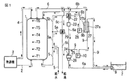
図1に示すように、貯湯タンク1の底部に配管2を介して加熱手段である熱源機3の流入口が接続され、その熱源機3の流出口に配管4を介して貯湯タンク1の上部が接続される。熱源機3は、ヒートポンプ式冷凍サイクルを備え、配管2から流入する水を外気から汲み上げた熱で加熱して温水化する。この温水が配管4によって貯湯タンク1の上部に導かれることにより、貯湯タンク1に温水が貯留される。貯湯タンク1の底部は、給水管5を介して水道等の給水源にも接続され、その給水源から水の補給を受ける。
Hereinafter, an embodiment will be described with reference to the drawings.
As shown in FIG. 1, an inlet of a heat source unit 3 as a heating means is connected to the bottom of a hot
貯湯タンク1には、深さ方向に沿って複数の温度センサT6,T5,T4,T3,T2,T1が順次に取付けられている。これら温度センサの検知温度から、貯湯タンク1の深さ方向における温水の温度分布および量を捕らえることができるとともに、貯湯タンク1内の温水が有する熱量を検出することが可能である。
A plurality of temperature sensors T6, T5, T4, T3, T2, and T1 are sequentially attached to the hot
貯湯タンク1の上部に高温水を出湯する出湯管6が接続され、その出湯管6から浴槽7の循環口8にかけて給湯管6aが接続される。この給湯管6aに、混合弁21、温度センサ22、温水供給手段であるホッパ23、温度センサ24、流れ検知手段であるフロースイッチ25、浴槽7の水位を検知する水位センサ26が設けられる。
A hot water discharge pipe 6 for discharging hot water is connected to the upper part of the hot
上記混合弁21は、出湯管6から導かれる高温水に対し、上記給水管5から分岐したバイパス管5bから導かれる水を混合することにより、設定温度の温水を生成する。設定温度は、後述のリモートコントローラ40で設定される湯はり設定温度Thsのことである。温度センサ22は、混合弁21から流出する温水の温度Th1を検知する。この検知温度Th1が上記湯はり設定温度Thsとなるよう、混合弁21における水の混合割合が後述の制御部30によって調整される。
The
上記ホッパ23は、給湯管6aの流路を導通/遮断する開閉弁、およびその開閉弁を通る温水の流量を検知するセンサを有し、このセンサの検知に基づく送湯量が後述の制御部30で算出されつつ開閉弁が開閉されることにより、浴槽7の形状や大きさを考慮して予め定められた設定量の温水を浴槽7へと供給する。設定量については、当該給湯装置の据付け時における初期運転によって自動的に検出されて設定される。
The
そして、浴槽7の循環口8から、給湯管6aにおけるホッパ23の配設位置より下流側位置にかけて、循環用配管9が接続される。そして、循環用配管9に、風呂熱交換器27の風呂側流路27aおよび循環ポンプ10が設けられる。循環ポンプ10が動作すると、浴槽7の湯水が循環口8、給湯管6aの一部、循環用配管9、風呂熱交換器27の風呂側流路27a、を通って循環する。これら、循環口8、給湯管6aの一部、循環用配管9、循環ポンプ10および風呂熱交換器27の風呂側流路27aにより、浴槽7の湯水を保温(追い炊きともいう)するための保温流路が形成される。この保温流路を流れる湯水の温度Th2が上記温度センサ24で検知されるとともに、その湯水の流れが上記フロースイッチ25で検知される。
Then, the
一方、上記出湯管6から分岐した循環用配管6bが上記風呂熱交換器27の熱源側流路27bおよび循環ポンプ28を介して貯湯タンク1の上部に接続される。循環ポンプ28が動作すると、貯湯タンク1の高温水が風呂熱交換器27の熱源側流路27bを通って循環し、上記保温流路を通る湯水が加温される。
On the other hand, the
また、出湯管6から湯の使用場所である台所、洗面所、風呂場シャワー等にかけて給湯管6cが配設され、その給湯管6cに混合弁29が設けられる。混合弁29は、出湯管6から導かれる高温水に対し、上記給水管5から分岐したバイパス管5aから導かれる水を混合することにより、設定温度の温水を生成する。ここでの設定温度は、後述のリモートコントローラ40で設定される給湯設定温度のことである。
A hot
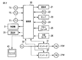
このような構成の給湯装置の制御回路を図2に示す。
制御部30に、温度センサT6,T5,T4,T3,T2,T1、熱源機3、混合弁21、温度センサ22、ホッパ23、温度センサ24、フロースイッチ25、水位センサ26、混合弁29、インバータ31,32、およびリモートコントローラ40が接続される。
FIG. 2 shows a control circuit of the water heater having such a configuration.
インバータ31は、交流電源33の交流電圧を直流に変換し、それを制御部30からの指令に応じたスイッチングにより所定周波数の交流電圧に変換し、それを循環ポンプ10のモータ10Mに対する駆動電力として出力する。インバータ32は、交流電源33の交流電圧を直流に変換し、それを制御部30からの指令に応じたスイッチングにより所定周波数の交流電圧に変換し、それを循環ポンプ28のモータ28Mに対する駆動電力として出力する。これらインバータ31,32では、モータ10M,28Mの巻線に流れる電流が検出され、その検出電流に応じたロータ回転位置の情報が制御部30に供給される。
The
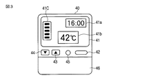
リモートコントローラ40は、浴槽7の近傍に設置され、運転モード、湯はり設定温度、保温温度、給湯設定温度などの運転条件を設定するためのもので、図3に示すように、各種情報を表示する液晶表示部41、運転の開始と停止を指示するための運転ボタン42、設定温度調節用の温度調節ボタン43,44、給湯可能量の表示を指示するための給湯可能量表示ボタン45、運転モードの選択ボタンなどを含む操作部を開閉自在に閉塞する開閉カバー46などを有する。選択ボタンで選択可能な運転モードとして、浴槽7に適温・適量の湯を溜める湯はり運転、浴槽7の湯を保温する保温運転、浴槽7に足し湯する足し湯運転などがある。
The
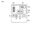
上記液晶表示部41は、現在時刻・タイマ時間・給湯可能量などを数値表示する数値表示領域41a、設定温度(湯はり設定温度、給湯設定温度、シャワー設定温度など)を数値表示する温度表示領域41b、残湯量を複数のバーによりレベル表示する残湯量表示領域41cなどを有する。数値表示領域41aには、通常は現在時刻やタイマ時間が表示され、給湯可能量表示ボタン45が押圧操作されると図4に示すように給湯可能量が数値表示される。
The liquid
制御部30は、主要な機能として次の(1)〜(8)の手段を有する。
(1)循環ポンプ10の動作、フロースイッチ25の検知、ホッパ23の動作、水位センサ26の検知により、浴槽7に湯を溜める第1湯はり運転を実行する制御手段。具体的には、循環ポンプ10の動作およびフロースイッチ25の検知結果から浴槽7内の残水の有無を判定し、残水なしの場合にホッパ23により設定量の温水を浴槽7に供給し、この供給後の浴槽7の湯量を循環ポンプ10の動作およびフロースイッチ25の検知結果から判定し、湯量が適正であれば、循環ポンプ10の動作により浴槽7の湯を風呂熱交換器27に通して循環させる保温動作を行うとともに、水位センサ26の検知水位が設定値未満となったときにホッパ23の動作により浴槽7に所定量の湯を足す足し湯動作を行う、
(2)ホッパ23の動作のみで浴槽7に湯を溜める第2湯はり運転の制御手段。すなわち、ホッパ23の動作のみで浴槽7に設定量の温水を供給する。
The
(1) Control means for executing a first hot water operation for accumulating hot water in the bathtub 7 by the operation of the
(2) Second hot water operation control means for storing hot water in the bathtub 7 only by the operation of the
(3)循環ポンプ10、フロースイッチ25、および水位センサ26の異常をそれぞれ検出する異常検出手段。循環ポンプ10については、インバータ31から供給されるロータ回転位置の情報に基づいてモータ10Mの実際の速度を求め、求めた速度とモータ10Mに対して指定した速度との差が所定値以上の場合に、異常と判定する。フロースイッチ25については、そのフロースイッチ25に温水や湯水が流れない状況であるにもかかわらず、フロースイッチ25がオンしている場合に、異常と判定する。水位センサ26は検知した圧力から水位を検出するものであり、その水位センサ26の検知結果である圧力が大気圧を含む所定圧力範囲から外れている場合に、異常と判定する。
(3) Abnormality detection means for detecting abnormalities in the
(4)上記異常検出手段で異常が検出されない場合に上記第1湯はり運転の実行を選択し、異常が検出された場合は上記第2湯はり運転の実行を選択する選択手段。 (4) Selection means for selecting execution of the first hot water beam operation when no abnormality is detected by the abnormality detection means, and selecting execution of the second hot water beam operation when an abnormality is detected.
(5)温度センサT6,T5,T4,T3,T2,T1の検知温度から貯湯タンク1の残湯量を算出する算出手段。
(5) Calculation means for calculating the remaining hot water amount in the hot
(6)温度センサT6,T5,T4,T3,T2,T1の検知温度から貯湯タンク1内の温水の熱量を算出し、算出した熱量とリモートコントローラ40の操作による設定温度(温度表示領域41bで表示されている設定温度)とに基づき貯湯タンク1からの給湯可能量を算出する算出手段。この給湯可能量の算出は、一定時間ごとに、かつ設定温度が変更されるごとに、実施する。
(6) The amount of hot water in the hot
(7)上記算出される残湯量をリモートコントローラ40の液晶表示部41におけるレベル表示領域41で表示する制御手段。
(7) Control means for displaying the calculated remaining hot water amount in the
(8)通常は現在時刻やタイマ時間をリモートコントローラ40の液晶表示部41における数値表示領域41aで表示し、リモートコントローラ40の貯湯量表示ボタン45が押圧操作されると、上記算出される給湯可能量を一定時間たとえば10秒間だけ液晶表示部41のレベル表示領域41で表示する制御手段。
(8) Normally, the current time and timer time are displayed in the numerical
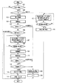
つぎに、図5のフローチャートを参照しながら作用について説明する。
リモートコントローラ40で湯はり運転モードが設定されると(ステップ101のYES)、異常停止フラグfが確認される(ステップ102)。異常停止フラグfが“0”であれば(ステップ102のYES)、異常停止がなかったとの判断の下に、第1湯はり運転が実行される。
Next, the operation will be described with reference to the flowchart of FIG.
When the hot water operation mode is set by the remote controller 40 (YES in step 101), the abnormal stop flag f is confirmed (step 102). If the abnormal stop flag f is “0” (YES in step 102), the first hot water operation is executed based on the determination that there is no abnormal stop.
この第1湯はり運転では、まず、浴槽7内の残水いわゆる残り湯の有無を判定する残り湯確認が実施される(ステップ103)。すなわち、循環ポンプ10が動作するとともに、それに伴うフロースイッチ25の状態変化が監視される。浴槽7内の湯水が循環口8以上に残っていれば、その湯水が循環口8、給湯管6aの一部、循環用配管9、循環ポンプ10および風呂熱交換器27の風呂側流路27aを通って循環する。この循環が始まると、フロースイッチ25の状態がオフからオンに変化する。このフロースイッチ25の状態変化に基づき、残り湯ありが判定される。仮に、浴槽7内の湯水が循環口8以上に残っていなければ、循環ポンプ10が動作しても湯水が循環しないので、フロースイッチ25がオフ状態を維持する。この場合、残り湯なしが判定される。
In the first hot water beam operation, first, the remaining hot water confirmation for determining the presence or absence of the remaining water in the bathtub 7 so-called remaining hot water is performed (step 103). That is, the circulating
この残り湯確認に伴い、循環ポンプ10、フロースイッチ25、水位センサ26に異常があるかどうかを判定する異常検出が実施される(ステップ104)。
Along with the remaining hot water confirmation, abnormality detection is performed to determine whether or not the
循環ポンプ10、フロースイッチ25、水位センサ26のいずれにも異常がなく(ステップ105のYES)、しかも残り湯なしの場合(ステップ106のYES)、混合弁21が開かれて貯湯タンク1の高温水が給湯管6aに流れるとともに、温度センサ22の検知温度Thが湯はり設定温度Thsとなるよう、混合弁21における水の混合量が調整される(ステップ107)。そして、ホッパ23の開閉弁が開き、温水が浴槽7に供給される。このとき、ホッパ23の送湯量がそのホッパ23のセンサを通して検出され、検出される送湯量と浴槽7の形状や大きさに対応する設定量とが比較される(ステップ108)。
If there is no abnormality in any of the
送湯量が設定量以上になると(ステップ108のYES)、ホッパ23の開閉弁が閉じられて浴槽7への温水の供給が終了し、浴槽7の湯量を循環ポンプ10の動作およびフロースイッチ25の検知結果から判定する湯量確認が実施される(ステップ109)。湯量が十分であれば、湯が循環口8、給湯管6aの一部、循環ポンプ10、循環用配管9および風呂熱交換器27の風呂側流路27aを通って循環する。この循環により、フロースイッチ25がオンする。このフロースイッチ25のオンに基づき、湯量が適正であると判定される。ただし、浴槽7の栓が抜けていたり確実に嵌まっていない場合、ホッパ23から供給される温水が漏れ、浴槽7に十分な量の湯が溜まらなくなる。この場合、循環ポンプ10が動作しても湯が循環せず、フロースイッチ25がオフ状態を維持する。この場合、湯量が適正でないと判定される。
When the amount of hot water supply exceeds the set amount (YES in step 108), the open / close valve of the
この湯量確認に伴い、循環ポンプ10、フロースイッチ25、水位センサ26に異常があるかどうかを判定する異常検出が実施される(ステップ110)。
With this hot water amount confirmation, abnormality detection is performed to determine whether or not the
循環ポンプ10、フロースイッチ25、水位センサ26のいずれにも異常がなく(ステップ111のYES)、しかも湯量が適正であれば(ステップ112のYES)、湯はり完了の旨がリモートコントローラ40のブザー鳴動やランプ点灯によって報知される(ステップ113)。
If there is no abnormality in any of
この報知に続き、循環ポンプ10の動作により浴槽7の湯を風呂熱交換器27の風呂側流路に通して循環させ、かつ貯湯タンク1の高温水を循環ポンプ28の動作により風呂熱交換器27の熱源側流路に通して循環させる保温動作が行われるとともに、水位センサ26の検知水位が設定値未満となったときにホッパ23の開閉弁を開いて浴槽7に所定量の湯を足す足し湯動作が行われる(ステップ114)。
Following this notification, the hot water in the bathtub 7 is circulated through the bath-side flow path of the
ところで、残り湯確認に伴う異常検出(ステップ104)において循環ポンプ10、フロースイッチ25、水位センサ26のいずれかの異常ありが判定された場合(ステップ105のNO)、直ちに湯はり運転が停止され、その異常停止の旨がリモートコントローラ40で報知される(ステップ115)。湯量確認に伴う異常検出(ステップ110)において循環ポンプ10、フロースイッチ25、水位センサ26のいずれかの異常ありが判定された場合も(ステップ111のNO)、直ちに湯はり運転が停止され、その異常停止の旨がリモートコントローラ40で報知される(ステップ115)。湯量確認において湯量が適正でないと判定された場合も(ステップ112のNO)、直ちに湯はり運転が停止され、その異常停止の旨がリモートコントローラ40で報知される(ステップ115)。そして、これら異常停止に際し、異常停止フラグfが“1”にセットされる(ステップ116)。
By the way, if any abnormality of the
異常停止したことを知ったユーザがリモートコントローラ40で再び湯はり運転モードを設定すると(ステップ101のYES)、異常停止フラグfが確認される(ステップ102)。このとき、異常停止フラグfが“1”なので(ステップ102のNO)、第1湯はり運転において異常停止があったとの判断の下に、第2湯はり運転が実行される。 When a user who knows that an abnormal stop has occurred sets the hot water operation mode again with the remote controller 40 (YES in step 101), the abnormal stop flag f is confirmed (step 102). At this time, since the abnormal stop flag f is “1” (NO in step 102), the second hot water beam operation is executed based on the determination that an abnormal stop has occurred in the first hot water beam operation.
この第2湯はり運転では、混合弁21が開かれて貯湯タンク1の高温水が給湯管6aに流れるとともに、温度センサ22の検知温度Thが湯はり設定温度Thsとなるよう、混合弁21における水の混合量が調整される(ステップ117)。そして、ホッパ23の開閉弁が開き、給湯管6aの温水が浴槽7に供給される。このとき、ホッパ23の送湯量がそのホッパ23のセンサを通して検出され、検出される送湯量と浴槽7の形状や大きさに対応する設定量とが比較される(ステップ118)。
In this second hot water operation, the mixing
送湯量が設定量以上になると(ステップ118のYES)、ホッパ23の開閉弁が閉じられて浴槽7への高温水の供給が終了し、湯はり完了の旨がリモートコントローラ40のブザー鳴動やランプ点灯によって報知される(ステップ119)。
When the amount of hot water supply exceeds the set amount (YES in step 118), the open / close valve of the
この第2湯はり運転では、残り湯確認および湯量確認が省略されるものの、少なくとも、浴槽7に設定量の温水を供給して溜めるという最低限の目標は達成される。したがって、ユーザは、異常が生じた部品の点検や交換を待つことなく、湯がはられた浴槽7に入ることができる。 In the second hot water operation, although the remaining hot water confirmation and the hot water amount confirmation are omitted, at least the minimum target of supplying and storing a set amount of hot water to the bathtub 7 is achieved. Therefore, the user can enter the bathtub 7 in which hot water has been poured out without waiting for inspection or replacement of the part in which an abnormality has occurred.
部品の点検や交換が完了して異常が解除されると、リモートコントローラ40での作業員によるリセット操作に基づき、異常停止フラグfが“0”にリセットされる。これにより、第1湯はり運転の実行が可能となる。
When the inspection or replacement of the parts is completed and the abnormality is released, the abnormal stop flag f is reset to “0” based on the reset operation by the operator at the
なお、上記第1湯はり運転と第2湯はり運転は、リモートコントローラ40に選択操作可能なボタン等を設け、ユーザが手動により任意に選択可能としても良い。
The first hot water operation and the second hot water operation may be arbitrarily selected manually by the user by providing a button or the like that can be selected and operated on the
一方、リモートコントローラ40の貯湯量表示ボタン45が押圧操作されると、図4に示すように、給湯可能量たとえば180Lが10秒間だけ液晶表示部41の数値表示領域41aで数値表示される。この給湯可能量は、一定時間ごとに、しかも設定温度が変更されるごとに算出される。したがって、湯の使用、外気温度の変化、設定温度の変更などに応じて変わる最新の給湯可能量をユーザに的確に知らせることができる。
On the other hand, when the hot water storage
なお、上記実施形態は、例として提示したものであり、発明の範囲を限定することは意図していない。この新規な実施形態は、その他の様々な形態で実施されることが可能であり、発明の要旨を逸脱しない範囲で、種々の省略、書き換え、変更を行うことができる。この実施形態や変形は、発明の範囲は要旨に含まれるとともに、特許請求の範囲に記載された発明とその均等の範囲に含まれる。 The above embodiment is presented as an example, and is not intended to limit the scope of the invention. The novel embodiment can be implemented in various other forms, and various omissions, rewrites, and changes can be made without departing from the spirit of the invention. The scope of the invention is included in the gist of the embodiments and modifications, and is included in the invention described in the claims and the equivalent scope thereof.
1…貯湯タンク、3…熱源機、5…給湯管、5a,5b…バイパス管、6…出湯管、6a…給湯管、6b…循環用配管、6c…給湯管、7…浴槽、8…循環口、9…循環用配管、10…循環ポンプ、10M…モータ、21…混合弁、22…温度センサ、23…ホッパ、24…温度センサ、25…フロートスイッチ(流れ検知手段)、26…水位センサ(水位検知手段)、27…風呂熱交換器、28…循環ポンプ、28M…モータ、30…制御部、T6〜T1…温度センサ、31,32…インバータ、40…リモートコントローラ、41…液晶表示部、41a…数値表示領域、41b…温度表示領域、41c…残湯量表示領域
DESCRIPTION OF
Claims (3)
上記加熱手段で加熱された温水を貯留する貯湯タンクと、
上記貯湯タンクの底部に接続され、給水源から貯湯タンクへ水を供給する給水管と、
上記貯湯タンク上部から高温水を出湯する出湯管と、
上記出湯管から導かれる高温水と水を混合して設定温度の温水を生成する混合弁と、
上記混合弁で生成された温水を浴槽に供給する温水供給手段と、
上記貯湯タンクの温水と上記浴槽の湯水との熱交換を行うための風呂熱交換器と、
上記浴槽の湯水を上記風呂熱交換器に通して循環させる循環ポンプと、
上記循環ポンプにより循環する温水の流れを検知する流れ検知手段と、
上記浴槽の水位を検知する水位検知手段と、
上記循環ポンプの動作、上記流れ検知手段の検知、上記温水供給手段の動作、上記水位検知手段の検知により、上記浴槽に湯を溜める第1湯はり運転を実行する制御手段と、
上記温水供給手段の動作のみで上記浴槽に湯を溜める第2湯はり運転を実行する制御手段と、
を備えることを特徴とする給湯装置。 Heating means for heating water to warm it;
A hot water storage tank for storing hot water heated by the heating means;
A water supply pipe connected to the bottom of the hot water storage tank for supplying water from a water supply source to the hot water storage tank;
A tapping pipe for tapping hot water from the upper part of the hot water storage tank;
A mixing valve that mixes high-temperature water and water led from the outlet pipe to generate hot water at a set temperature;
Hot water supply means for supplying hot water generated by the mixing valve to the bathtub;
A bath heat exchanger for exchanging heat between the hot water in the hot water storage tank and the hot water in the bathtub;
A circulation pump for circulating hot water in the bathtub through the bath heat exchanger;
Flow detection means for detecting the flow of hot water circulated by the circulation pump;
Water level detecting means for detecting the water level of the bathtub;
Control means for executing a first hot water operation for storing hot water in the bathtub by the operation of the circulation pump, the detection of the flow detection means, the operation of the hot water supply means, and the detection of the water level detection means;
Control means for executing a second hot water operation for storing hot water in the bathtub only by the operation of the hot water supply means;
A hot water supply apparatus comprising:
上記異常検出手段で異常が検出されない場合に上記第1湯はり運転の実行を選択し、異常が検出された場合に上記第2湯はり運転の実行を選択する選択手段と、
をさらに備えることを特徴とする請求項1記載の給湯装置。 An abnormality detection means for detecting an abnormality in each of the circulation pump, the flow detection means, and the water level detection means;
Selecting means for selecting execution of the first hot water beam operation when no abnormality is detected by the abnormality detecting means, and selecting execution of the second hot water beam operation when an abnormality is detected;
The hot water supply apparatus according to claim 1, further comprising:
上記第2湯はり運転は、上記温水供給手段の動作のみで上記浴槽に設定量の温水を供給する、
ことを特徴とする請求項1または請求項2記載の給湯装置。 In the first hot water beam operation, the presence or absence of residual water in the bathtub is determined from the operation of the circulation pump and the detection result of the flow detection means, and when there is no residual water, a set amount of hot water is supplied by the hot water supply means. The amount of hot water in the bathtub that is supplied to the bathtub is determined from the operation of the circulation pump and the detection result of the flow detection means. If the amount of hot water is appropriate, the hot water in the bathtub is A warming operation that circulates through a bath heat exchanger, and a hot water operation that adds a predetermined amount of hot water to the bathtub by the operation of the hot water supply means when the detected water level of the water level detection means becomes less than a set value And
In the second hot water beam operation, a set amount of hot water is supplied to the bathtub only by the operation of the hot water supply means.
The hot water supply apparatus according to claim 1 or claim 2, wherein
Priority Applications (1)
| Application Number | Priority Date | Filing Date | Title |
|---|---|---|---|
| JP2010237553A JP2012088024A (en) | 2010-10-22 | 2010-10-22 | Apparatus for supplying hot water |
Applications Claiming Priority (1)
| Application Number | Priority Date | Filing Date | Title |
|---|---|---|---|
| JP2010237553A JP2012088024A (en) | 2010-10-22 | 2010-10-22 | Apparatus for supplying hot water |
Publications (1)
| Publication Number | Publication Date |
|---|---|
| JP2012088024A true JP2012088024A (en) | 2012-05-10 |
Family
ID=46259818
Family Applications (1)
| Application Number | Title | Priority Date | Filing Date |
|---|---|---|---|
| JP2010237553A Pending JP2012088024A (en) | 2010-10-22 | 2010-10-22 | Apparatus for supplying hot water |
Country Status (1)
| Country | Link |
|---|---|
| JP (1) | JP2012088024A (en) |
Citations (3)
| Publication number | Priority date | Publication date | Assignee | Title |
|---|---|---|---|---|
| JP2000283555A (en) * | 1999-03-31 | 2000-10-13 | Toto Ltd | Remote control device for water heater |
| JP2005344972A (en) * | 2004-06-01 | 2005-12-15 | Corona Corp | Hot water storage type water heater |
| JP2009192189A (en) * | 2008-02-18 | 2009-08-27 | Panasonic Corp | Hot water heater with bath hot water function |
-
2010
- 2010-10-22 JP JP2010237553A patent/JP2012088024A/en active Pending
Patent Citations (3)
| Publication number | Priority date | Publication date | Assignee | Title |
|---|---|---|---|---|
| JP2000283555A (en) * | 1999-03-31 | 2000-10-13 | Toto Ltd | Remote control device for water heater |
| JP2005344972A (en) * | 2004-06-01 | 2005-12-15 | Corona Corp | Hot water storage type water heater |
| JP2009192189A (en) * | 2008-02-18 | 2009-08-27 | Panasonic Corp | Hot water heater with bath hot water function |
Similar Documents
| Publication | Publication Date | Title |
|---|---|---|
| JP5827865B2 (en) | Water heater | |
| JP5897937B2 (en) | Bath equipment | |
| JP2007032904A (en) | Cogeneration system | |
| JP6066563B2 (en) | Water heater | |
| JP2012088024A (en) | Apparatus for supplying hot water | |
| JP2009052760A (en) | Hot water storage water heater | |
| JP2014047967A (en) | Water heater | |
| JP5956830B2 (en) | Water heater | |
| JP2011080682A (en) | Storage water heater | |
| JP5458967B2 (en) | Hot water storage water heater | |
| JP3856042B1 (en) | Water heater | |
| JP6225815B2 (en) | Hot water system | |
| JP2016191485A (en) | Hot water storage type water heater | |
| JP2014228151A (en) | Bath water heater | |
| JP6223136B2 (en) | Cogeneration system | |
| JP2013242091A (en) | Storage type water heater | |
| JP5098582B2 (en) | Water heater with automatic bath function | |
| JP2008232478A (en) | Hot water supply apparatus | |
| JP4639059B2 (en) | Hot water supply system | |
| JP2008002784A (en) | Hot water supply device for bath | |
| JP2021162288A (en) | Hot water storage type water heater | |
| JP6120752B2 (en) | Cogeneration system | |
| JP2014025597A (en) | Storage water heater | |
| JP5388608B2 (en) | Hot water storage water heater | |
| JP6086820B2 (en) | Water heater |
Legal Events
| Date | Code | Title | Description |
|---|---|---|---|
| RD02 | Notification of acceptance of power of attorney |
Free format text: JAPANESE INTERMEDIATE CODE: A7422 Effective date: 20130815 |
|
| A621 | Written request for application examination |
Free format text: JAPANESE INTERMEDIATE CODE: A621 Effective date: 20131003 |
|
| A977 | Report on retrieval |
Free format text: JAPANESE INTERMEDIATE CODE: A971007 Effective date: 20140613 |
|
| A131 | Notification of reasons for refusal |
Free format text: JAPANESE INTERMEDIATE CODE: A131 Effective date: 20140617 |
|
| A521 | Request for written amendment filed |
Free format text: JAPANESE INTERMEDIATE CODE: A523 Effective date: 20140811 |
|
| A02 | Decision of refusal |
Free format text: JAPANESE INTERMEDIATE CODE: A02 Effective date: 20141202 |