JP5956830B2 - Water heater - Google Patents
Water heater Download PDFInfo
- Publication number
- JP5956830B2 JP5956830B2 JP2012112690A JP2012112690A JP5956830B2 JP 5956830 B2 JP5956830 B2 JP 5956830B2 JP 2012112690 A JP2012112690 A JP 2012112690A JP 2012112690 A JP2012112690 A JP 2012112690A JP 5956830 B2 JP5956830 B2 JP 5956830B2
- Authority
- JP
- Japan
- Prior art keywords
- hot water
- pump
- pipe
- turned
- bath pump
- Prior art date
- Legal status (The legal status is an assumption and is not a legal conclusion. Google has not performed a legal analysis and makes no representation as to the accuracy of the status listed.)
- Expired - Fee Related
Links
Images



Landscapes
- Control For Baths (AREA)
- Heat-Pump Type And Storage Water Heaters (AREA)
Description
本発明の実施形態は、貯湯タンクの湯を浴槽に供給する給湯装置に関する。 Embodiments of the present invention relate to a hot water supply apparatus that supplies hot water in a hot water storage tank to a bathtub.
貯湯タンクを収容した貯湯タンクユニット、およびその貯湯タンク内の湯水を加熱するヒートポンプユニットを備え、貯湯タンクに貯えた湯を貯湯タンクユニットから建屋内の浴槽等に供給する給湯装置が知られている。 2. Description of the Related Art There is known a hot water supply device that includes a hot water storage tank unit that houses a hot water storage tank and a heat pump unit that heats the hot water in the hot water storage tank, and supplies hot water stored in the hot water storage tank from a hot water storage tank unit to a bathtub in a building. .
この給湯装置には、貯湯タンク内の湯を浴槽に供給する給湯いわゆる湯はりのほかに、浴槽内の湯水を加温用の熱交換器に通して循環させる保温や追炊きの機能がある。 This hot water supply device has not only hot water supply that supplies hot water in a hot water storage tank to a bathtub, but also a function of heat insulation and cooking that circulates hot water in the bathtub through a heat exchanger for heating.
保温や追い炊きなどの循環運転を行うと、浴槽内の湯水の汚れが配管、熱交換器、ポンプ等の内側に徐々に蓄積し、その汚れの蓄積が抵抗となって湯水の循環不良を生じることがある。 When the circulating operation such as heat insulation or additional cooking is performed, the hot water in the bathtub gradually accumulates inside the piping, heat exchanger, pump, etc., and the accumulation of the soil becomes a resistance, resulting in poor hot water circulation. Sometimes.
本発明の実施形態の目的は、湯水の循環不良を解消できる給湯装置を提供することである。 An object of an embodiment of the present invention is to provide a hot water supply device that can eliminate poor circulation of hot water.
本発明の実施形態の給湯装置は、湯を浴槽に供給するものであって、配管と、この配管に設けたポンプと、検知手段と、制御手段とを備える。配管は、浴槽内の湯水を加温用の熱交換器に通して循環させる。ポンプは、湯水循環用である。検知手段は、配管内の湯水の流量が一定以上であるかを検知する。制御手段は、ポンプの運転にもかかわらず検知手段で一定以上の流量が検知されないまま一定時間が経過した場合、ポンプを一旦停止して複数回にわたりオン,オフしてから同ポンプをその停止前より高い回転数で運転する。 A hot water supply apparatus according to an embodiment of the present invention supplies hot water to a bathtub, and includes a pipe, a pump provided in the pipe, a detection unit, and a control unit. The piping circulates hot water in the bathtub through a heat exchanger for heating. The pump is for hot water circulation. A detection means detects whether the flow volume of the hot water in piping is more than fixed. If a certain amount of time has passed without the detection means detecting a flow rate in spite of the operation of the pump, the control means will stop the pump once and turn it on / off several times before the pump is stopped. It operated at higher speed.
以下、一実施形態について図面を参照して説明する。
図1において、1は屋外に設置される給湯ユニット(貯湯タンクユニットともいう)で、外部の給水管A1から水が供給される。この水が配管2により且つその配管2上の減圧弁3および逆止弁4を介して貯湯タンク5の底部流入口に導かれる。配管2における減圧弁3と逆止弁4との間を流れる水の一部は逆止弁6を介して混合弁7の第1流入口に導かれ、その混合弁7から流出する湯水が配管8により外部の給湯管A2に供給される。配管8には流量センサ9が取付けられる。給湯管A2は、台所、洗面所、浴室シャワー等に延設される。混合弁7の第2流入口は、配管10を介して貯湯タンク5の上部流出口に接続される。
Hereinafter, an embodiment will be described with reference to the drawings.
In FIG. 1, 1 is a hot water supply unit (also called a hot water storage tank unit) installed outdoors, and water is supplied from an external water supply pipe A1. This water is led to the bottom inlet of the hot water storage tank 5 by the
配管10の中途部に逆止弁11が配置され、その配管10における逆止弁11より上流側の湯が混合弁12の第1流入口に導かれる。この混合弁12の第2流入口には、上記配管2における減圧弁3と逆止弁4との間の水が導かれる。そして、混合弁12で混合された湯水が配管14により且つその配管14上のホッパ15、銀イオン発生器20、フロースイッチ21を介して屋外の配管A3に供給される。この配管A3は、建屋の中に導入されて浴室60の浴槽61の循環金具62に接続される。ホッパ15は、開閉弁16、逆止弁17、流量センサ18、および逆止弁19を有する。配管14には、フロースイッチ21の配設位置の近傍に、内部の湯水の温度Trを検知する水温センサ(温度検知手段)22、および配管14,A3を通して浴槽61内の湯水の水位を検知する水位センサ23が取付けられる。フロースイッチ21は、配管A3,14内を通る湯水の流量が一定以上か否かを検知する検知手段として機能するもので、一定以上の場合にオンして一定未満の場合はオフする。
A
また、配管14の銀イオン発生器20を経た湯水の一部は、ふろポンプ24および配管25を通って加温用の熱交換器26の第1流路に供給され、その第1流路を経た湯水が配管27により屋外の配管A4に供給される。この配管A4も、建屋の中に導入されて浴槽61の循環金具62に接続される。配管27には、配管A4に向かって流れる湯の温度Tiを検知する湯温センサ28が取付けられる。
A part of the hot water that has passed through the
上記配管10における逆止弁11より上流側の湯が配管30により且つその配管30上の逆止弁31を介して上記熱交換器26の第2流路に導かれ、その第2流路を経た湯が配管32、追炊きポンプ33、および配管44により貯湯タンク5の上部流入口に供給される。
Hot water on the upstream side of the
貯湯タンク5の底部流出口から流出する湯水が配管40および循環ポンプ41により外部の配管A5に供給される。この配管A5は加熱手段であるヒートポンプユニット70の入水口に接続される。そして、配管40における循環ポンプ41より上流側位置が三方弁42の第1流出口に接続され、その三方弁42の流入口が配管43により外部の配管A6に接続される。この配管A6は、ヒートポンプユニット70の流出口に接続される。三方弁42は、配管43から流入する湯を第1流出口および第2流出口のいずれか一方または両方から流出させる。第2流出口から流出する湯は上記配管44により貯湯タンク5の上部流入口に導かれる。配管43に入水温度センサ45が取付けられ、配管44に沸上げ温度センサ46が取付けられる。入水温度センサ45は、配管A6から給湯ユニット1に流入する湯水の温度Tt1を検知する、沸上げ温度センサ46は、配管44から貯湯タンク5の上部流入口に流れる湯の温度Tt2を検知する。
Hot water flowing out from the bottom outlet of the hot water storage tank 5 is supplied to the external pipe A5 by the
貯湯タンク5内の湯水の温度および水位は、その貯湯タンク5の下部から上部にかけて順に配置された複数の温度センサT1,T2,…T6により検知される。 The temperature and water level of the hot water in the hot water storage tank 5 are detected by a plurality of temperature sensors T1, T2,... T6 arranged in order from the lower part to the upper part of the hot water storage tank 5.
上記ヒートポンプユニット70は、圧縮機71、水-冷媒熱交換器72の冷媒側流路、内部熱交換器73の第1流路、減圧器たとえば膨張弁74、空気熱交換器75、および内部熱交換器73の第2流路を順次に接続して冷媒を循環させるヒートポンプ式冷凍サイクルを有するとともに、空気熱交換器75に外気を送るファン76、上記配管A5から流入する湯水を水-冷媒熱交換器72の水側流路に導く配管77、水-冷媒熱交換器72の水側流路から流出する湯を上記配管A6に導く配管78、配管77内の湯水の温度Twiを検知する給水温度センサ81、および配管78内の湯の温度Twoを検知する沸上げ温度センサ82を有し、給湯ユニット1から供給される湯水を外気から汲み上げた熱で加熱し、その加熱により得られる湯を給湯ユニット1へ供給する。
The
また、給湯ユニット1にコントローラ50が設けられ、そのコントローラ50に給湯ユニット1内の弁・ポンプ・温度センサ、外気温度センサ83、浴室60のリモートコントロール式操作器(操作手段;リモコンと略称する)63、およびヒートポンプユニット70が接続される。
In addition, a
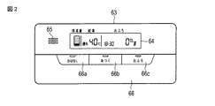
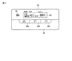
リモコン63は、図2に示すように、液晶表示部64、音声入出力部65、および操作扉66を前面に有する。操作扉66は、会話モード設定用の“おはなし”ボタン66a、保温・追炊き運転設定用の“あつく”ボタン66b、給湯運転設定用の“おふろ”ボタン66cを有する。この操作扉66を開いて露出する盤面には、ボタン66a,66b,66cの押圧操作にそれぞれ連動する複数のボタンスイッチが配置されるとともに、ほかにメニューボタンスイッチ、給湯温度設定ボタンスイッチ、優先/決定ボタンスイッチ、洗浄運転指定用の洗浄ボタンスイッチ、たし湯ボタンスイッチ、ふろ湯量設定タンスイッチ、ふろ温度設定タンスイッチなどが配置される。液晶表示部64は、貯湯量、給湯温度、時刻、使用湯量などのパターン情報や文字情報を表示するとともに、異常報知として図3に示すような“詰まり”という文言を表示することができる。
As shown in FIG. 2, the
コントローラ50は、当該給水装置の全体を制御するもので、主要な機能として次の(1)〜(7)の制御手段を有する。
(1)貯湯タンク5内の湯水をヒートポンプユニット70によって加熱し、この加熱により得られる湯を貯湯タンク5に貯える貯湯運転の実行を制御する第1制御手段。
The
(1) First control means for controlling the execution of a hot water storage operation in which hot water in the hot water storage tank 5 is heated by the
(2)貯湯タンク5内の湯を配管A3,A4を通して浴槽61に供給する給湯運転(湯はり運転ともいう)の実行を制御する第2制御手段。
(2) Second control means for controlling execution of a hot water supply operation (also referred to as hot water operation) for supplying hot water in the hot water storage tank 5 to the
(3)ふろポンプ24の運転により、浴槽61内の湯水を配管A3,A4および熱交換器26に通して循環させる保温用・追い炊き用の循環運転の実行を制御する第3制御手段。
(3) Third control means for controlling execution of the circulating operation for warming and cooking, in which hot water in the
(4)リモコン63の洗浄ボタンスイッチが押圧操作された場合、貯湯タンク5内の湯水が配管10,14と配管A3を通って浴槽61に流れ、かつ配管14における銀イオン発生器20を経た湯水の一部がふろポンプ24、配管25、熱交換器26、配管27、配管A4を通って浴槽61に流れる洗浄用流路を一定時間だけ形成し、その形成時に銀イオン発生器20を動作させる洗浄運転の実行を制御する第4制御手段。
(4) When the washing button switch of the
(5)上記循環運転時、ふろポンプ24の運転にもかかわらずフロースイッチ21がオンしないまま一定時間t1s(例えば40〜60秒)が経過したとき、ふろポンプ24の回転数Nを高める第5制御手段。なお、ふろポンプ24のモータは、駆動電力を出力するインバータに接続される。このインバータの出力周波数を変化させることで、ふろポンプ24の回転数が変化する。
(5) During the above-described circulation operation, when the predetermined time t1s (for example, 40 to 60 seconds) elapses without the
(6)ふろポンプ24の回転数Nを高めたにもかかわらずフロースイッチ21がオンしないまま一定時間t3s(例えば40〜60秒)が経過したとき、ふろポンプ24の運転を停止してリモコン63で異常を報知し且つ以後のふろポンプ24による循環運転を禁止する第6制御手段。
(6) When the predetermined time t3s (for example, 40 to 60 seconds) elapses without the
(7)第6制御手段による異常の報知および循環運転の禁止を以後の上記洗浄運転の実行または異常のリセット操作に応じて解除する第7制御手段。 (7) Seventh control means for releasing the abnormality notification and the circulation operation prohibition by the sixth control means in response to the subsequent execution of the cleaning operation or the abnormality reset operation.
つぎに、動作について説明する。
例えば深夜電力時間帯において、ヒートポンプユニット70における圧縮機71が運転オンされ、その圧縮機71から吐出される冷媒が水-冷媒熱交換器72の冷媒側流路、内部熱交換器73の第1流路、膨張弁74、空気熱交換器75、内部熱交換器73の第2流路を通って圧縮機71に吸込まれる。これに伴い、給湯ユニット1の循環ポンプ41が運転オンされるとともに三方弁42の第1流出口と流入口が連通され、貯湯タンク5の下部の湯水が配管40、循環ポンプ41、配管A5、配管77を通って水-冷媒熱交換器72の水側流路に流れ、その水-冷媒熱交換器72で加熱された湯が配管78、配管A6、配管43、三方弁42を通って配管40に戻る。
Next, the operation will be described.
For example, in the late-night power hours, the
配管78を通る湯の温度Twoが沸上げ温度センサ82により検知されており、その検知温度が予め定められた貯湯温度に達すると、三方弁42が切換えられてその流入口と第2流出口とが連通する。この三方弁42の切換えに伴い、水-冷媒熱交換器72で加熱された湯が配管78、配管A6、配管43、三方弁42、配管44を通って貯湯タンク5の上部に流れる。これにより、貯湯タンク5に湯が貯えられる。
When the temperature Two of the hot water passing through the
リモコン63の “おふろ”ボタン66cが押圧操作されると、ホッパ15の開閉弁16が開放されるとともに銀イオン発生器20がオンされる。これにより、貯湯タンク5内の湯が配管10、混合弁12、配管14、ホッパ15、銀イオン発生器20、フロースイッチ21、配管A3を通って浴槽61に供給されるとともに、銀イオン発生器20を経た湯の一部がふろポンプ24、配管25、熱交換器26、配管27、配管A4を通る経路でも浴槽61に供給される。このとき、銀イオン発生器20が銀イオンを発生し、その銀イオンが配管14内の湯に与えられる。また、浴槽61への給湯量がホッパ15内の流量センサ18によって検知されており、その検知量がリモコン63の設定湯量に達すると、ホッパ15の開閉弁16が閉成されるとともに銀イオン発生器20がオフされ、湯はり運転が終了する。
この湯はり運転の終了後、定期的または不定期のタイミングでふろポンプ24が運転オンされ、図1に破線矢印で示すように、浴槽61内の湯が配管A3、配管14、ふろポンプ24、配管25、熱交換器26の第1流路、配管27、配管A4を通って循環する。このとき、配管14を通る湯の温度が湯温センサ22によって検知され、その検知温度がリモコン63の設定湯温に達していなければ追炊きポンプ33が運転オンされる。追炊きポンプ33が運転オンすると、貯湯タンク5内の湯が配管10、配管30、熱交換器26の第2流路、配管32、追炊きポンプ33、配管44を通って循環し、熱交換器26の第2流路を通る湯の熱で同熱交換器26の第1流路を通る浴槽循環の湯が加熱される。こうして加熱された湯が浴槽61に戻り、浴槽61内の湯が保温される。湯温センサ22の検知温度が設定湯温に達すると、ふろポンプ24および追炊きポンプ33が運転オフされて保温用の循環運転が終了する。
When the “bath”
After completion of the hot water operation, the
リモコン63のあつくボタン66bが押圧操作された場合も、同様の循環運転により浴槽61内の湯が追炊きされる。
Even when the
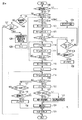
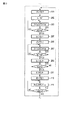
このような保温用あるいは追い炊き用の循環運転、あるいは当該給湯装置が設置された直後の作業員による循環試運転に際し、ふろポンプ24の運転に関し図4のフローチャートに示す制御が実行される。
すなわち、循環運転の開始に際し(ステップ100のYES)、後述の循環運転禁止モードが設定されていないことを条件に(ステップ101のYES)、かつ回転数フラグfが“0”であることを条件に(ステップ102のYES)、ふろポンプ24が通常回転数N1たとえば4000rpmで運転オンされる(ステップ103)。この運転オンに伴い、タイムカウントt1が実行され(ステップ105)、そのタイムカウントt1と一定時間t1s(40〜60秒)とが比較される(ステップ106)。タイムカウントt1が一定時間t1s未満のとき(ステップ106のNO)、フロースイッチ21がオンするかどうか監視される(ステップ107)。フロースイッチ21がオフの場合(ステップ107のNO)、ステップ105に戻り、タイムカウントt1が繰り返される。
In such a heat-retaining or additional cooking circulation operation or a circulation trial operation by an operator immediately after the hot water supply apparatus is installed, the control shown in the flowchart of FIG.
That is, at the start of the circulating operation (YES in step 100), on condition that the later-described circulating operation prohibition mode is not set (YES in step 101), and that the rotational speed flag f is “0”. In step 102 (YES in step 102), the
タイムカウントt1が一定時間t1sに達しないうちにフロースイッチ21がオンすると(ステップ106のNO、ステップ107のYES)、湯温センサ22の検知温度が設定湯温に達するなど循環運転の終了条件が満足される状態にあるかどうか監視される(ステップ108)。循環運転の終了条件が満足される状態になければ(ステップ108のNO)、ステップ107に戻り、フロースイッチ21の監視が繰り返される。その後、循環運転の終了条件が満足される状態になると(ステップ108のYES)、ふろポンプ24が運転オフされる(ステップ109)。この運転オフにより、循環運転が終了する。そして、タイムカウントt1,t2がリセットされる(ステップ125)。
If the
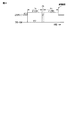
ただし、図5に示すように、フロースイッチ21がオンしないままタイムカウントt1が一定時間t1sに達した場合には(ステップ106のYES)、つまりふろポンプ24の運転オンにもかかわらず配管A3,14内の湯水の流量が一定以上とならない場合は、湯水の循環が不良であるとの判断の下に、ふろポンプ24が運転オフされる(ステップ110)。これに伴い、タイムカウントt2が実行され(ステップ111)、そのタイムカウントt2と一定時間t2s(10秒)とが比較される(ステップ112)。そして、タイムカウントt2が一定時間t2sに達すると(ステップ112のYES)、ふろポンプ24が通常回転数N1より高い回転数N2たとえば4500rpmで運転オンされる(ステップ113)。このとき、回転数フラグfが“1”にセットされる(ステップ114)。
However, as shown in FIG. 5, when the time count t1 reaches a certain time t1s without the
配管A3,A4などの締め付けが悪い場合など、空気が配管A3,A4中に混入し、混入した空気が細かな粒となってふろポンプ24の中に溜まり込む。溜まり込む空気の粒が増えると、ふろポンプ24の送水効率が低下し、湯水の循環不良が生じる。このような不具合を防ぐため、上記のようにふろポンプ24の運転を一旦オフしてからオンするようにしている。ふろポンプ24が一旦オフすると、ふろポンプ24内で滞留する細かな空気の粒がふろポンプ24の上方部に集まって固まり、その固まりが次のふろポンプ24のオンによってふろポンプ24の外に一気に排出される。この排出により、湯水の循環不良を解消することができる。
When the tightening of the pipes A3, A4, etc. is poor, the air enters the pipes A3, A4, and the mixed air becomes fine particles and accumulates in the
この回転数上昇によるふろポンプ24の運転オンに伴い、タイムカウントt3が実行され(ステップ115)、そのタイムカウントt3と一定時間t3s(40〜60秒)とが比較される(ステップ116)。タイムカウントt1が一定時間t3s未満のとき(ステップ116のNO)、フロースイッチ21がオンするかどうか監視される(ステップ117)。フロースイッチ21がオフであれば(ステップ117のNO)、ステップ115に戻り、タイムカウントt3が繰り返される。
With the operation of the
タイムカウントt3が一定時間t3sに達しないうちにフロースイッチ21がオンすると(ステップ117のYES)、湯温センサ22の検知温度が設定湯温に達するなど循環運転の終了条件が満足される状態にあるかどうか監視される(ステップ118)。循環運転の終了条件が満足される状態になければ(ステップ108のNO)、ステップ117に戻り、フロースイッチ21の監視が繰り返される。その後、循環運転の終了条件が満足される状態になると(ステップ118のYES)、ふろポンプ24が運転オフされる(ステップ119)。この運転オフにより、循環運転が終了する。そして、タイムカウントt1,t2,t3がリセットされる(ステップ125)。
If the
しかしながら、図6に示すように、フロースイッチ21がオンしないままタイムカウントt3が一定時間t3sに達した場合には(ステップ116のYES)、つまりふろポンプ24の回転数上昇による運転オンにもかかわらず配管A3,14内の湯水の流量が一定以上とならない場合には、湯水の循環が不良であるとの判断の下に、ふろポンプ24が運転オフされる(ステップ120)。
However, as shown in FIG. 6, when the time count t3 reaches a certain time t3s without the
このふろポンプ24の運転オフ時、水位センサ23の検知水位(浴槽61内の湯水の水位)が一定以上の状態にあれば(ステップ121のYES)、汚れが配管A3,14に詰まって湯水の流れが悪くなる詰まり異常が生じたとして、図3に示すように、リモコン63の液晶表示部64で“詰まり”という文言を表示する詰まり異常報知が行われる(ステップ122)。そして、以後の循環運転を禁止する循環運転禁止モードが設定されるとともに(ステップ124)、タイムカウントt1,t2,t3がリセットされる(ステップ125)。
When the
この詰まり異常の表示を見たユーザーは、配管が汚れで詰まっていることを察知し、リモコン63で洗浄運転を指定して配管A3,14を洗浄したり、販売店やメーカーに点検・保守のサービスを依頼する。当該給湯装置を設置した直後の作業員による循環試運転に際して詰まり異常の表示が出た場合は、作業員は、施工した配管に何か詰まっていなかったか、定格より細い配管を誤って施工しなかったか、定格より長い配管を誤って施工しなかったかなど、作業内容を確認し、必要に応じて配管を取り換えるなどの処置を行う。
The user who sees this clogging abnormality notices that the piping is clogged with dirt, and designates the cleaning operation with the
ふろポンプ24の運転オフ時、水位センサ23の検知水位が一定未満の場合は(ステップ121のNO)、浴槽61内に湯水が無いままふろポンプ24が空運転する空運転異常が生じたとして、リモコン63の液晶表示部64で“空運転”という文言を表示する空運転詰異常報知が行われる(ステップ123)。そして、以後の循環運転を禁止する循環運転禁止モードが設定されるとともに(ステップ124)、タイムカウントt1,t2,t3がリセットされる(ステップ125。
If the water level detected by the
この空運転異常の表示を見たユーザーは、ポンプが空運転していることを察知し、浴槽61の湯水や栓を確認したり、販売店やメーカーに点検・保守のサービスを依頼する。当該給湯装置を設置した直後の作業員による循環試運転に際して空運転異常の表示が出た場合は、作業員は、浴槽61の湯水や栓を確認したり、施工した配管の水漏れを確認するなど、適宜な処置を行う。
The user who sees the indication of the abnormal operation of the idle air senses that the pump is idling, checks the hot water and the stopper of the
詰まり異常や空運転異常が生じてふろポンプ24が運転オフした後は、リモコン63で循環運転の開始が再度指定されても(ステップ100のYES)、循環運転禁止モードが設定されているので(ステップ101のNO)、ユーザー指定による洗浄運転が実行済みでなければ(ステップ126のNO)、また作業員やユーザーによる異常のリセット操作が例えばリモコン63でなされていなければ(ステップ127のNO)、ふろポンプ24が運転オンされることはなく、安全である。
After the clogging abnormality or the idling operation abnormality occurs and the
詰まり異常や空運転異常の後でユーザー指定による洗浄運転が実行されると(ステップ126のYES)、あるいは作業員が配管の施工をやり直すなどして作業員やユーザーによる異常のリセット操作がなされると(ステップ127のYES)、上記異常報知および循環運転禁止モードが解除されるとともに(ステップ128)、回転数フラグfが“0”にリセットされる(ステップ129)。 When a cleaning operation specified by the user is executed after a clogging abnormality or an empty operation abnormality (YES in step 126), or the worker resets the abnormality by the worker or the user by redoing the piping. (YES in step 127), the abnormality notification and the circulation operation prohibition mode are canceled (step 128), and the rotation speed flag f is reset to “0” (step 129).
次の循環運転の開始に際して循環運転禁止モードが解除されていれば(ステップ100のYES、ステップ101のYES)、かつ回転数フラグfが“0”にリセットされていれば(ステップ102のYES)、ふろポンプ24が通常回転数N1で運転オンされる(ステップ103)。
If the circulation operation prohibition mode is canceled at the start of the next circulation operation (YES in
一方、ふろポンプ24が回転数N2で運転オンし、そのまま異常が生じることなく循環運転の終了条件が満足されてふろポンプ24が運転オフした場合には、次の循環運転の開始に際し(ステップ100のYES)、循環運転禁止モードが設定されていないので(ステップ101のYES)、しかも回転数フラグfが“1”であることにより(ステップ102のNO)、図7に示すように、ふろポンプ24が初めから回転数N2で運転オンされる(ステップ104)。こうして、ふろポンプ24が通常回転数N1より高い回転数N2で運転オンすることにより、配管A3,14内の汚れがそれほどひどくない状況であれば、循環運転を続けることができる。
On the other hand, when the
ただし、配管A3,14内の汚れがひどい場合、あるいは配管A3,14に何か詰まった場合、あるいは施工した配管A3が定格より細い場合、あるいは施工した配管A3が定格より長い場合、あるいは浴槽61内に湯水が無い場合など、たとえふろポンプ24が通常回転数N1より高い回転数N2で運転オンしても、図7に示すように、フロースイッチ21がオンしないままタイムカウントt1が一定時間t1sに達することがある(ステップ106のYES)。この場合は、タイムカウントt2に基づく一定時間t2sだけふろポンプ24が運転オフされ(ステップ110、ステップ111、ステップ112のYES)、この後、ふろポンプ24が回転数N2で再び運転オンされる(ステップ113)。これに伴い、回転数フラグfが“1”にセットされるとともに(ステップ114)、タイムカウントt3が開始される(ステップ115)。そして、図8に示すように、フロースイッチ21がオンしないままタイムカウントt3が一定時間t3sに達した場合には(ステップ116のYES)、湯水の循環が不良であるとの判断の下に、ふろポンプ24が運転オフされるとともに(ステップ120)、上記同様の異常報知および運転禁止モード設定が行われる(ステップ121〜124)。
However, if the dirt in the pipes A3 and 14 is severe, or if the pipes A3 and 14 are clogged, or if the installed pipe A3 is thinner than the rating, or if the installed pipe A3 is longer than the rating, or the
以上のように、ふろポンプ24の運転にもかかわらず一定以上の流量の湯水が流れない場合はふろポンプ24の回転数Nを高めることにより、湯水の循環不良を解消することができる。仮に、回転数Nを高めても循環不良を解消できない場合は、異常を報知するので、循環不良がいつまでも続く不具合を解消できる。
As described above, in the case where hot water with a flow rate higher than a certain level does not flow despite the operation of the
ふろポンプ24の回転数Nを高める前にふろポンプ24の運転を一旦オフするので、細かな空気の粒による循環不良についても解消できる。
Since the operation of the
[変形例]
上記実施形態では、ふろポンプ24の回転数Nを高める前にふろポンプ24の運転を一度だけオフしたが、ふろポンプ24の回転数Nを高める前にふろポンプ24の運転を複数回にわたってオン,オフしてもよい。
この場合、図9に示すように、ステップ110,111,112の処理の前にステップ201〜211の処理が実行される。
[Modification]
In the above-described embodiment, the operation of the
In this case, as shown in FIG. 9,
すなわち、フロースイッチ21がオンしないままタイムカウントt1が一定時間t1sに達した場合(ステップ106のYES)、ふろポンプ24が運転オフされる(ステップ201)。このとき、回数カウントKが“1”アップされる(ステップ202)。そして、タイムカウントtxが実行され(ステップ203)、そのタイムカウントtxと一定時間txs(10秒)とが比較される(ステップ204)。そして、タイムカウントtxが一定時間txsに達すると(ステップ204のYES)、タイムカウントtxがリセットされるとともに(ステップ205)、ふろポンプ24が運転オンされる(ステップ206)。このときのふろポンプ24の回転数Nはそれ以前の制御状況に応じてN1,N2のどちらでもよい。
That is, when the time count t1 reaches the predetermined time t1s without turning on the flow switch 21 (YES in step 106), the
ふろポンプ24の運転オンに伴いタイムカウントtyが実行され(ステップ207)、そのタイムカウントtyと一定時間tys(例えば10秒)とが比較される(ステップ208)。タイムカウントtyが一定時間tysに達すると(ステップ208のYES)、タイムカウントtyがリセットされるとともに(ステップ209)、回数カウントKが設定値Ksたとえば“3”に達しているかどうか判定される(ステップ201)。回数カウントKが設定値Ksに達していなければ(ステップ210のNO)、ステップ201からの処理が繰り返される。回数カウントKが設定値Ksに達すると(ステップ210のYES)、回数カウントKがリセットされた後(ステップ211)、ふろポンプ24が運転オフされる(ステップ110)。以後の処理は上記実施形態と同じなので、その説明は省略する。
A time count ty is executed as the
このように、ふろポンプ24の回転数Nを高める前にふろポンプ24の運転を複数回にわたってオン,オフすることにより、例えば細かな空気の粒が多い場合でもそれによる循環不良を確実に解消できる。
In this way, by turning on and off the operation of the bath pump 24 a plurality of times before increasing the rotational speed N of the
なお、洗浄運転としては、上記第4制御手段による流路のものに限らず、追炊き運転時と同じ循環流路のものであってもよい。 The cleaning operation is not limited to the flow path by the fourth control means, but may be the same circulation flow path as that in the additional cooking operation.
その他、上記実施形態および変形例は、例として提示したものであり、発明の範囲を限定することは意図していない。この新規な各実施形態および変形例は、その他の様々な形態で実施されることが可能であり、発明の要旨を逸脱しない範囲で、種々の省略、書き換え、変更を行うことができる。これら実施形態や変形は、発明の範囲は要旨に含まれるとともに、特許請求の範囲に記載された発明とその均等の範囲に含まれる。 In addition, the said embodiment and modification are shown as an example and are not intending limiting the range of invention. Each of the novel embodiments and modifications can be implemented in various other forms, and various omissions, rewrites, and changes can be made without departing from the spirit of the invention. In these embodiments and modifications, the scope of the invention is included in the gist, and is included in the invention described in the claims and the equivalents thereof.
1…給湯ユニット、5…貯湯タンク、12…混合弁、14…配管、15…ホッパ、16…開閉弁、18…流量センサ、20…銀イオン発生器、21…フロースイッチ(検知手段)23…水位センサ、A3…配管、24…ふろポンプ、25…配管、26…熱交換器、27…配管、A4…配管、50…コントローラ、51…CPU、52…スイッチ、53…駆動回路、60…浴室、61…浴槽、63…リモコン
DESCRIPTION OF
Claims (3)
前記浴槽内の湯水を加温用の熱交換器に通して循環させる配管と、
前記配管に設けた湯水循環用のポンプと、
前記配管内の湯水の流量が一定以上であるかを検知する検知手段と、
前記ポンプの運転にもかかわらず前記検知手段で一定以上の流量が検知されないまま一定時間が経過した場合、前記ポンプを一旦停止して複数回にわたりオン,オフしてから同ポンプをその停止前より高い回転数で運転する制御手段と、
を備えることを特徴とする給湯装置。 In a hot water supply device for supplying hot water to a bathtub,
Piping for circulating hot water in the bathtub through a heat exchanger for heating;
A pump for circulating hot water provided in the pipe;
Detecting means for detecting whether the flow rate of the hot water in the pipe is above a certain level;
When a certain amount of time has passed without detecting the flow rate above a certain level in spite of the operation of the pump, the pump is temporarily stopped and turned on and off several times before the pump is stopped from before the stop. Control means operating at a high rotational speed;
A hot water supply apparatus comprising:
ことを特徴とする請求項1に記載の給湯装置。 When the control means does not detect a flow rate above a certain level despite increasing the number of rotations of the pump, the control means stops the pump and reports an abnormality.
The hot water supply apparatus according to claim 1 .
ことを特徴とする請求項1に記載の給湯装置。 The control means stops the pump to notify the abnormality and prohibits the operation of the pump when the detection means does not detect a flow rate higher than a certain level even though the rotation speed of the pump is increased. In addition, the abnormality notification and the prohibition of operation are canceled according to the subsequent execution of the cleaning operation on the piping or the reset operation of the abnormality.
The hot water supply apparatus according to claim 1 .
Priority Applications (1)
| Application Number | Priority Date | Filing Date | Title |
|---|---|---|---|
| JP2012112690A JP5956830B2 (en) | 2012-05-16 | 2012-05-16 | Water heater |
Applications Claiming Priority (1)
| Application Number | Priority Date | Filing Date | Title |
|---|---|---|---|
| JP2012112690A JP5956830B2 (en) | 2012-05-16 | 2012-05-16 | Water heater |
Publications (2)
| Publication Number | Publication Date |
|---|---|
| JP2013238374A JP2013238374A (en) | 2013-11-28 |
| JP5956830B2 true JP5956830B2 (en) | 2016-07-27 |
Family
ID=49763558
Family Applications (1)
| Application Number | Title | Priority Date | Filing Date |
|---|---|---|---|
| JP2012112690A Expired - Fee Related JP5956830B2 (en) | 2012-05-16 | 2012-05-16 | Water heater |
Country Status (1)
| Country | Link |
|---|---|
| JP (1) | JP5956830B2 (en) |
Families Citing this family (3)
| Publication number | Priority date | Publication date | Assignee | Title |
|---|---|---|---|---|
| JP6252290B2 (en) * | 2014-03-25 | 2017-12-27 | 三菱電機株式会社 | Hot water storage water heater |
| JP6976118B2 (en) * | 2017-09-26 | 2021-12-08 | 三菱電機株式会社 | Hot water supply system |
| JP7614072B2 (en) * | 2021-11-08 | 2025-01-15 | 株式会社コロナ | Storage tank type hot water supply device |
Family Cites Families (8)
| Publication number | Priority date | Publication date | Assignee | Title |
|---|---|---|---|---|
| JP3603734B2 (en) * | 2000-03-23 | 2004-12-22 | ダイキン工業株式会社 | Descaling method |
| JP3724475B2 (en) * | 2002-10-28 | 2005-12-07 | 松下電器産業株式会社 | Heat pump water heater |
| JP5203867B2 (en) * | 2008-09-17 | 2013-06-05 | 株式会社長府製作所 | Bath equipment |
| JP2010190466A (en) * | 2009-02-17 | 2010-09-02 | Sanyo Electric Co Ltd | Water heater |
| JP5244015B2 (en) * | 2009-04-08 | 2013-07-24 | 株式会社コロナ | Hot water storage water heater |
| JP5427510B2 (en) * | 2009-08-19 | 2014-02-26 | 東芝キヤリア株式会社 | Heat pump hot water supply system |
| JP5333122B2 (en) * | 2009-09-28 | 2013-11-06 | 三菱電機株式会社 | Bath hot water supply system |
| JP5498759B2 (en) * | 2009-10-30 | 2014-05-21 | 東芝キヤリア株式会社 | Water heater |
-
2012
- 2012-05-16 JP JP2012112690A patent/JP5956830B2/en not_active Expired - Fee Related
Also Published As
| Publication number | Publication date |
|---|---|
| JP2013238374A (en) | 2013-11-28 |
Similar Documents
| Publication | Publication Date | Title |
|---|---|---|
| AU2011257945B2 (en) | A water heating system | |
| JP5956830B2 (en) | Water heater | |
| CN107300202B (en) | Control method and system of hydraulic module, computer equipment and readable storage medium | |
| JP5866226B2 (en) | Water heater | |
| JP2015002863A (en) | Bathtub washing device | |
| US20070017551A1 (en) | Dishwasher fill control | |
| JP6523015B2 (en) | Hot water storage type water heater | |
| JP2015039605A (en) | Bathtub cleaning system | |
| JP5897937B2 (en) | Bath equipment | |
| JP5824609B2 (en) | Heat pump water heater | |
| US7797952B2 (en) | Defrosting method of drum-type washing machine | |
| JP5181734B2 (en) | Hot water storage water heater | |
| JP6625813B2 (en) | Hot water storage system | |
| JP6221507B2 (en) | Bathtub cleaning system | |
| JP4483734B2 (en) | Bathroom ventilation drying equipment | |
| JP6066563B2 (en) | Water heater | |
| JP5458967B2 (en) | Hot water storage water heater | |
| CN108354556A (en) | Wash the control method and washing electric appliance of electric appliance | |
| JP5138940B2 (en) | Heat source apparatus, drain treatment method thereof, and drain treatment program thereof | |
| TWI595197B (en) | Pressurized water method of hot-water heater, and hot-water heater having the same | |
| JP6545081B2 (en) | Hot water heater | |
| JP6111620B2 (en) | Bathtub cleaning equipment | |
| JP5694905B2 (en) | Heat pump type water heater | |
| JP6415070B2 (en) | Bathroom Dryer | |
| JP2017194250A (en) | Hot water supply apparatus and abnormality determination method thereof |
Legal Events
| Date | Code | Title | Description |
|---|---|---|---|
| A621 | Written request for application examination |
Free format text: JAPANESE INTERMEDIATE CODE: A621 Effective date: 20150406 |
|
| A977 | Report on retrieval |
Free format text: JAPANESE INTERMEDIATE CODE: A971007 Effective date: 20160108 |
|
| A131 | Notification of reasons for refusal |
Free format text: JAPANESE INTERMEDIATE CODE: A131 Effective date: 20160119 |
|
| A521 | Request for written amendment filed |
Free format text: JAPANESE INTERMEDIATE CODE: A523 Effective date: 20160322 |
|
| TRDD | Decision of grant or rejection written | ||
| A01 | Written decision to grant a patent or to grant a registration (utility model) |
Free format text: JAPANESE INTERMEDIATE CODE: A01 Effective date: 20160524 |
|
| A61 | First payment of annual fees (during grant procedure) |
Free format text: JAPANESE INTERMEDIATE CODE: A61 Effective date: 20160617 |
|
| R150 | Certificate of patent or registration of utility model |
Ref document number: 5956830 Country of ref document: JP Free format text: JAPANESE INTERMEDIATE CODE: R150 |
|
| R250 | Receipt of annual fees |
Free format text: JAPANESE INTERMEDIATE CODE: R250 |
|
| R250 | Receipt of annual fees |
Free format text: JAPANESE INTERMEDIATE CODE: R250 |
|
| R250 | Receipt of annual fees |
Free format text: JAPANESE INTERMEDIATE CODE: R250 |
|
| LAPS | Cancellation because of no payment of annual fees |