JP2012106366A - Liquid jet apparatus and control method therefor - Google Patents
Liquid jet apparatus and control method therefor Download PDFInfo
- Publication number
- JP2012106366A JP2012106366A JP2010255590A JP2010255590A JP2012106366A JP 2012106366 A JP2012106366 A JP 2012106366A JP 2010255590 A JP2010255590 A JP 2010255590A JP 2010255590 A JP2010255590 A JP 2010255590A JP 2012106366 A JP2012106366 A JP 2012106366A
- Authority
- JP
- Japan
- Prior art keywords
- nozzle
- liquid
- ejected
- nozzles
- ejection
- Prior art date
- Legal status (The legal status is an assumption and is not a legal conclusion. Google has not performed a legal analysis and makes no representation as to the accuracy of the status listed.)
- Withdrawn
Links
- 239000007788 liquid Substances 0.000 title claims abstract description 97
- 238000000034 method Methods 0.000 title claims description 13
- 230000007246 mechanism Effects 0.000 claims description 10
- 238000007639 printing Methods 0.000 abstract description 18
- 239000000976 ink Substances 0.000 description 153
- 101000746134 Homo sapiens DNA endonuclease RBBP8 Proteins 0.000 description 15
- 101000969031 Homo sapiens Nuclear protein 1 Proteins 0.000 description 15
- 102100021133 Nuclear protein 1 Human genes 0.000 description 15
- 238000013459 approach Methods 0.000 description 15
- 238000010586 diagram Methods 0.000 description 13
- 230000004048 modification Effects 0.000 description 11
- 238000012986 modification Methods 0.000 description 11
- 239000000758 substrate Substances 0.000 description 10
- 238000002347 injection Methods 0.000 description 9
- 239000007924 injection Substances 0.000 description 9
- 238000003860 storage Methods 0.000 description 9
- 239000003595 mist Substances 0.000 description 8
- 230000000694 effects Effects 0.000 description 6
- 230000014509 gene expression Effects 0.000 description 6
- 238000012545 processing Methods 0.000 description 6
- 238000004519 manufacturing process Methods 0.000 description 4
- 238000000926 separation method Methods 0.000 description 4
- NAWXUBYGYWOOIX-SFHVURJKSA-N (2s)-2-[[4-[2-(2,4-diaminoquinazolin-6-yl)ethyl]benzoyl]amino]-4-methylidenepentanedioic acid Chemical compound C1=CC2=NC(N)=NC(N)=C2C=C1CCC1=CC=C(C(=O)N[C@@H](CC(=C)C(O)=O)C(O)=O)C=C1 NAWXUBYGYWOOIX-SFHVURJKSA-N 0.000 description 2
- 230000009471 action Effects 0.000 description 2
- 230000015572 biosynthetic process Effects 0.000 description 2
- 239000003086 colorant Substances 0.000 description 2
- 230000001934 delay Effects 0.000 description 2
- 230000006866 deterioration Effects 0.000 description 2
- 230000007274 generation of a signal involved in cell-cell signaling Effects 0.000 description 2
- 238000007641 inkjet printing Methods 0.000 description 2
- 239000000463 material Substances 0.000 description 2
- 239000000243 solution Substances 0.000 description 2
- 238000012360 testing method Methods 0.000 description 2
- 230000007723 transport mechanism Effects 0.000 description 2
- 238000000018 DNA microarray Methods 0.000 description 1
- 238000003491 array Methods 0.000 description 1
- 230000008859 change Effects 0.000 description 1
- 239000004020 conductor Substances 0.000 description 1
- 238000009826 distribution Methods 0.000 description 1
- 239000013013 elastic material Substances 0.000 description 1
- 238000005401 electroluminescence Methods 0.000 description 1
- 230000002708 enhancing effect Effects 0.000 description 1
- 238000010438 heat treatment Methods 0.000 description 1
- 239000004973 liquid crystal related substance Substances 0.000 description 1
- 238000005192 partition Methods 0.000 description 1
- 230000000737 periodic effect Effects 0.000 description 1
- 230000009467 reduction Effects 0.000 description 1
- 238000004904 shortening Methods 0.000 description 1
Images


Landscapes
- Ink Jet (AREA)
Abstract
【課題】各ノズルから噴射された液体の着弾位置の誤差を簡易に抑制する。
【解決手段】印刷装置100は、複数のノズルNの各々からインクを噴射可能な記録ヘッド24と、複数のノズルNの各々からのインクの噴射を制御する制御部60とを具備する。制御部60は、複数のノズルNのうち相互に隣り合う第1ノズルN1および第2ノズルN2からのインクの噴射の要否を印刷データDPから判定し、第1ノズルN1および第2ノズルN2の双方からのインクの噴射が必要な場合に、第1ノズルN1と第2ノズルN2とでインクの噴射条件(噴射時点や飛翔速度)を相違させる。
【選択図】図4
An object of the present invention is to easily suppress an error in a landing position of liquid ejected from each nozzle.
A printing apparatus includes a recording head that can eject ink from each of a plurality of nozzles, and a control unit that controls ejection of ink from each of the plurality of nozzles. The control unit 60 determines whether or not it is necessary to eject ink from the first nozzle N1 and the second nozzle N2 adjacent to each other among the plurality of nozzles N, and determines whether the first nozzle N1 and the second nozzle N2 are used. When it is necessary to eject ink from both sides, the first nozzle N1 and the second nozzle N2 are made to have different ink ejection conditions (ejecting time and flying speed).
[Selection] Figure 4
Description
本発明は、インク等の液体を噴射する技術に関する。 The present invention relates to a technique for ejecting a liquid such as ink.
複数のノズルの各々からインク等の液体を噴射する液体噴射装置が従来から提案されている。例えば特許文献1には、主走査方向に移動する記録ヘッドに、副走査方向に沿って複数のノズルが形成されたインクジェット方式の印刷装置が開示されている。
Conventionally, a liquid ejecting apparatus that ejects a liquid such as ink from each of a plurality of nozzles has been proposed. For example,
ところで、各ノズルから噴射される液体で形成されるドットの高精細化やドットの形成の高速化(例えば印刷時間の短縮)を実現するためには各ノズルの高密度化が要求される。しかし、複数のノズルを高密度化する(例えば解像度が600dpiを上回る)ほど、各ノズルから噴射された液体の飛翔方向の誤差が顕在化し、液体の着弾位置の高精度な制御が困難となる。 By the way, in order to realize high definition of dots formed by the liquid ejected from each nozzle and high speed of dot formation (for example, shortening the printing time), it is required to increase the density of each nozzle. However, the higher the density of the plurality of nozzles (for example, the resolution exceeds 600 dpi), the more the error in the flying direction of the liquid ejected from each nozzle becomes obvious, and the highly precise control of the liquid landing position becomes more difficult.
特許文献1には、各ノズルから液体を噴射させたときに記録紙に印刷されるテストパターンを読取り、読取の結果に応じて各ノズルからの液体の噴射の時点を調整する構成が開示されている。しかし、特許文献1の技術ではテストパターンの形成や読取等の煩雑な処理が必要になるという問題がある。以上の事情を考慮して、本発明は、各ノズルから噴射された液体の着弾位置の誤差を簡易に抑制することを目的とする。
以上の課題を解決するために本発明が採用する手段を説明する。なお、本発明の理解を容易にするために、以下の説明では、本発明の要素と後述の実施形態の要素との対応を括弧書で付記するが、本発明の範囲を実施形態の例示に限定する趣旨ではない。 Means employed by the present invention to solve the above problems will be described. In order to facilitate the understanding of the present invention, in the following description, the correspondence between the elements of the present invention and the elements of the embodiments described later will be indicated in parentheses, but the scope of the present invention will be exemplified in the embodiments. It is not intended to be limited.
本発明の液体噴射装置は、複数のノズル(例えばノズルN)を含むノズル列(例えばノズル列28)の各々のノズルから液体(例えばインク)を噴射可能な液体噴射部(例えば記録ヘッド24)と、複数のノズルの各々からの液体噴射を制御する制御手段(例えば制御部60)とを具備し、制御手段は、複数のノズルのうち第1ノズル(例えば第1ノズルN1)および第2ノズル(例えば第2ノズルN2)からの液体噴射の要否を印刷データ(例えば印刷データDP)から判定し、第1ノズルおよび第2ノズルの双方からの液体噴射が必要な場合に、第1ノズルと第2ノズルとで液体の噴射条件を相違させる。 The liquid ejecting apparatus of the present invention includes a liquid ejecting section (for example, a recording head 24) that can eject liquid (for example, ink) from each nozzle of a nozzle array (for example, nozzle array 28) including a plurality of nozzles (for example, nozzle N). And a control means (for example, the control unit 60) for controlling the liquid ejection from each of the plurality of nozzles. The control means includes a first nozzle (for example, the first nozzle N1) and a second nozzle (for example, the plurality of nozzles). For example, the necessity of liquid ejection from the second nozzle N2) is determined from print data (for example, print data DP), and when the liquid ejection from both the first nozzle and the second nozzle is necessary, the first nozzle and the second nozzle The liquid injection conditions are different between the two nozzles.
各ノズルを高密度化した場合に顕在化する着弾位置の誤差等の問題は、各ノズルから飛翔する液体の過度な接近が原因のひとつであると推察される。本発明の液体噴射装置においては、第1ノズルおよび第2ノズルの双方からの液体噴射が必要な場合に、相異なる噴射条件のもとで第1ノズルおよび第2ノズルの各々から液体が噴射されるから、相互に共通の噴射条件で各ノズルから液体が噴射される構成と比較して、第1ノズルから飛翔する液体と第2ノズルから飛翔する液体とを充分に離間させることが可能である。したがって、各ノズルから噴射された液体の接近に起因した着弾位置の誤差等の問題を抑制することが可能である。 Problems such as landing position errors that become apparent when the density of each nozzle is increased are presumed to be one of the causes of excessive approach of liquid flying from each nozzle. In the liquid ejecting apparatus of the present invention, when liquid ejection from both the first nozzle and the second nozzle is necessary, the liquid is ejected from each of the first nozzle and the second nozzle under different ejection conditions. Therefore, it is possible to sufficiently separate the liquid flying from the first nozzle and the liquid flying from the second nozzle as compared with the configuration in which the liquid is ejected from each nozzle under a common ejection condition. . Therefore, it is possible to suppress problems such as landing position errors caused by the approach of liquid ejected from each nozzle.
以上の説明から理解されるように、第1ノズルと第2ノズルとは、典型的には、相互に共通の噴射条件で液体を噴射させた場合に各液体の接近に起因して着弾位置の誤差等の問題が発生し得る程度に近い位置(例えば中心間の距離が後述の限界距離を下回る程度に近い位置)に形成された関係にある。例えば、第2ノズルは複数のノズルのうち第1ノズルに最も近いノズルである。ただし、着弾位置の誤差等が発生し得る程度に相互に近い位置に形成された関係にある任意のノズル(すなわち、相互に隣り合うか否かは不問)が第1ノズルおよび第2ノズルに該当し得る。なお、以上の説明では第1ノズルおよび第2ノズルのみに言及したが、液体噴射部に形成されるノズルの総数は本発明において任意である。すなわち、多数のノズルが液体噴射部に形成された構成でも、そのうちの2個を第1ノズルおよび第2ノズルとして把握した場合に前述の要件を充足する構成は、当然に本発明の範囲に包含される。 As understood from the above description, the first nozzle and the second nozzle typically have a landing position due to the approach of each liquid when the liquid is jetted under a common jetting condition. There is a relationship formed at a position close to a level where a problem such as an error may occur (for example, a position where the distance between the centers is below a limit distance described later). For example, the second nozzle is the nozzle closest to the first nozzle among the plurality of nozzles. However, any nozzles that are formed in positions close to each other to the extent that landing position errors can occur (that is, whether or not they are adjacent to each other) correspond to the first nozzle and the second nozzle. Can do. In the above description, only the first nozzle and the second nozzle are mentioned, but the total number of nozzles formed in the liquid ejecting portion is arbitrary in the present invention. That is, even in a configuration in which a large number of nozzles are formed in the liquid ejecting portion, a configuration that satisfies the above-described requirements when two of them are grasped as the first nozzle and the second nozzle is naturally included in the scope of the present invention. Is done.
また、以上の説明から理解されるように、本発明における各ノズルからの液体の噴射条件は、典型的には、各ノズルから飛翔する液体の間隔に影響する条件を意味する。本発明に適用され得る具体的な噴射条件としては、各ノズルからの液体の噴射の時点(例えば時点t1と時点t2との時間差ΔT)や、各ノズルから噴射された液体の速度(飛翔速度V1や飛翔速度V2)が例示される。 Further, as can be understood from the above description, the condition for ejecting liquid from each nozzle in the present invention typically means a condition that affects the interval between liquids flying from each nozzle. Specific ejection conditions that can be applied to the present invention include the time of liquid ejection from each nozzle (for example, the time difference ΔT between time t1 and time t2) and the speed of the liquid ejected from each nozzle (flying speed V1). And flight speed V2).
なお、各ノズルから噴射される液体の間隔を充分に確保するという観点のみからすれば、各ノズルからの液体の噴射条件を大きく相違させた構成が好適である。しかし、各ノズルから噴射された液体が着弾する着弾対象に対して液体噴射部を相対移動させる移動機構(例えば移動機構14)を具備する構成では、第1ノズルと第2ノズルとで液体の噴射条件が過度に相違させた場合、第1ノズルから噴射された液体で着弾対象に形成される第1ドット(例えばドットD1)と第2ノズルから噴射された液体で着弾対象に形成される第2ドット(例えばドットD2)とが相互に離間する(したがって、例えば液体噴射装置を画像印刷に利用した場合には印刷品位が低下する)という問題がある。そこで、本発明の好適な態様では、第1ノズルから噴射された液体で着弾対象に形成される第1ドットと、第2ノズルから噴射された液体で着弾対象に形成される第2ドットとが、相対移動の方向について相互に接触または重複するように、第1ノズルおよび第2ノズルの各々における液体の噴射条件が選定される。以上の態様では、第1ドットと第2ドットとが相互に接触または重複するように第1ノズルおよび第2ノズルの各々における液体の噴射条件が選定されるから、各ノズルから噴射された液体の接近に起因した着弾位置の誤差等を抑制しながら、第1ドットと第2ドットとの過度な離間(例えば印刷品位の低下)を抑制することが可能である。なお、以上の態様では、液体噴射部の相対移動の方向における分布範囲が第1ドットと第2ドットとで接触または重複すれば足り、液体噴射部の相対移動の方向に直交する方向(例えば副走査方向)における第1ドットと第2ドットとの接触/離間は不問である。 From the viewpoint of ensuring a sufficient interval between the liquids ejected from the nozzles, a configuration in which the conditions for ejecting the liquids from the nozzles are greatly different is preferable. However, in a configuration including a moving mechanism (for example, the moving mechanism 14) that moves the liquid ejecting unit relative to the landing target on which the liquid ejected from each nozzle lands, the liquid is ejected by the first nozzle and the second nozzle. When the conditions are excessively different, the first dot (for example, dot D1) formed on the landing target with the liquid ejected from the first nozzle and the second formed on the landing target with the liquid ejected from the second nozzle. There is a problem that the dots (for example, the dot D2) are separated from each other (therefore, for example, when the liquid ejecting apparatus is used for image printing, the print quality is lowered). Therefore, in a preferred aspect of the present invention, the first dots formed on the landing target with the liquid ejected from the first nozzle and the second dots formed on the landing target with the liquid ejected from the second nozzle are provided. The liquid ejection conditions in each of the first nozzle and the second nozzle are selected so as to contact or overlap each other in the direction of relative movement. In the above aspect, since the liquid ejection conditions in each of the first nozzle and the second nozzle are selected so that the first dot and the second dot contact or overlap each other, the liquid ejected from each nozzle It is possible to suppress excessive separation between the first dot and the second dot (for example, deterioration of print quality) while suppressing an error in the landing position due to the approach. In the above aspect, it is sufficient that the distribution range in the relative movement direction of the liquid ejecting unit is in contact with or overlapping with the first dot and the second dot, and a direction orthogonal to the direction of relative movement of the liquid ejecting unit (e.g. The contact / separation between the first dot and the second dot in the scanning direction is not questioned.
以上の各態様に係る液体噴射装置の動作方法(液体噴射装置の制御方法)としても本発明は特定され得る。本発明の制御方法は、複数のノズルの各々から液体を噴射可能な液体噴射部を具備する液体噴射装置について複数のノズルの各々からの液体噴射を制御する制御方法であって、複数のノズルのうち第1ノズルおよび第2ノズルからの液体噴射の要否を印刷データから判定し、第1ノズルおよび第2ノズルの双方からの液体噴射が必要な場合に、第1ノズルと第2ノズルとで液体の噴射条件を相違させる。本発明の制御方法によれば、本発明の液体噴射装置と同様の作用および効果が実現される。 The present invention can also be specified as a method of operating the liquid ejecting apparatus according to each of the above aspects (a method of controlling the liquid ejecting apparatus). A control method of the present invention is a control method for controlling liquid ejection from each of a plurality of nozzles in a liquid ejecting apparatus including a liquid ejecting unit capable of ejecting liquid from each of a plurality of nozzles. Of these, when the necessity of liquid ejection from the first nozzle and the second nozzle is determined from the print data, and liquid ejection from both the first nozzle and the second nozzle is necessary, the first nozzle and the second nozzle Different liquid injection conditions. According to the control method of the present invention, the same operation and effect as the liquid ejecting apparatus of the present invention are realized.
<A:第1実施形態>
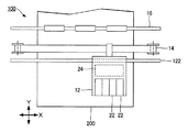
図1は、本発明の第1実施形態に係るインクジェット方式の印刷装置100の部分的な模式図である。印刷装置100は、微細なインクの液滴(以下「インク滴」という)を記録紙200に噴射する液体噴射装置であり、キャリッジ12と移動機構14と用紙搬送機構16とを具備する。
<A: First Embodiment>
FIG. 1 is a partial schematic view of an ink
キャリッジ12には、インクカートリッジ22と記録ヘッド24とが搭載される。インクカートリッジ22は、記録紙200に噴射されるインク(液体)を貯留する容器である。記録ヘッド24は、インクカートリッジ22に貯留されたインクを記録紙200に噴射する液体噴射部として機能する。なお、印刷装置100の筐体(図示略)にインクカートリッジ22を固定して記録ヘッド24にインクを供給する構成も採用され得る。
An
移動機構14は、案内軸122に沿ってキャリッジ12をX方向(記録紙200の幅方向に相当する主走査方向)に往復させる。キャリッジ12の位置は、リニアエンコーダー等の検出器(図示略)で検出されて移動機構14の制御に利用される。用紙搬送機構16は、キャリッジ12の往復に並行して記録紙200をY方向(副走査方向)に移動させる。キャリッジ12の往復時に記録ヘッド24が記録紙200にインク滴を順次に噴射することで所望の画像が記録紙200に記録(印刷)される。
The moving
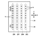
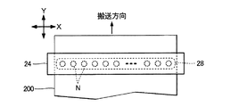
図2は、記録ヘッド24のうち記録紙200に対向する吐出面26の平面図である。図2に示すように、記録ヘッド24の吐出面26には、相異なるインク色(ブラック(K),イエロー(Y),マゼンタ(M),シアン(C))に対応する複数(図2では4列)のノズル列28(28K,28Y,28M,28C)が形成される。複数のノズル列28の各々は、複数のノズル(吐出口)Nの集合である。ノズル列28Kの各ノズルNからはブラック(K)のインク滴が吐出される。同様に、ノズル列28Yの各ノズルNからはイエロー(Y)のインク滴が吐出され、ノズル列28Mの各ノズルNからはマゼンタ(M)のインク滴が吐出され、ノズル列28Cの各ノズルNからはシアン(C)のインク滴が吐出される。各ノズル列28内の複数のノズルNは、各々の中心間に間隔dをあけてY方向に直線状に配列する。各ノズルNの間隔dは、例えば600dpi(dot per inch)を上回る解像度に対応する寸法に設定される。
FIG. 2 is a plan view of the
図3は、記録ヘッド24の断面図(X方向に垂直な断面)である。図3に示すように、記録ヘッド24は、振動ユニット42と収容体44と流路ユニット46とを具備する。振動ユニット42は、圧電振動子422とケーブル424と固定板426と含む。圧電振動子422は、圧電材料と電極とが交互に積層された縦振動型の圧電素子であり、ケーブル424を介して供給される駆動信号に応じて振動する。圧電振動子422を固定した固定板426が収容体44の内壁面に接合された状態で振動ユニット42は収容体44に収容される。
FIG. 3 is a sectional view of the recording head 24 (cross section perpendicular to the X direction). As shown in FIG. 3, the
流路ユニット46は、相互に対向する基板462と基板464との間隙に流路形成板466を介挿した構造体である。基板462のうち基板464とは反対側の表面が図2の吐出面26に相当する。流路形成板466は、圧力室50と供給路52と貯留室54とを含む空間を基板462と基板464との間隙に形成する。圧力室50は、振動ユニット42毎に隔壁で個別に区画されるとともに供給路52を介して貯留室54に連通する。インクカートリッジ22から供給されるインクは貯留室54に貯留される。図2の各ノズルNは、各圧力室50に対応するように基板462に形成される。各ノズルNは、圧力室50に連通する貫通孔である。以上の説明から理解されるように、貯留室54から供給路52と圧力室50とノズルNとを経由して外部に至るインクの流路が形成される。
The
基板464は、弾性材料で形成された平板材である。基板464のうち圧力室50の反対側の領域には島状の振動板48が形成される。振動板48には圧電振動子422の先端面(自由端)が接合される。したがって、駆動信号の供給により圧電振動子422が振動すると、振動板48を介して基板464が変位することで圧力室50の容積が変化して圧力室50内のインクの圧力が変動する。すなわち、圧電振動子422は、圧力室50内の圧力を変動させる圧力発生素子として機能する。以上に説明した圧力室50内の圧力の変動に応じてノズルNからインク滴を噴射することが可能である。
The
図4は、印刷装置100の電気的な構成のブロック図である。図4に示すように、印刷装置100は、制御装置102と印刷処理部(プリントエンジン)104とを具備する。制御装置102は、印刷装置100の全体を制御する要素であり、制御部60と記憶部62と駆動信号発生部64と外部I/F(interface)66と内部I/F68とを含む。記録紙200に印刷される画像を示す印刷データDPが外部装置(例えばホストコンピューター)300から外部I/F66に供給され、内部I/F68には印刷処理部104が接続される。印刷処理部104は、制御装置102による制御のもとで記録紙200に画像を記録する要素であり、前述の記録ヘッド24と移動機構14と用紙搬送機構16とを含む。
FIG. 4 is a block diagram of an electrical configuration of the
図4の記憶部62は、制御プログラム等を記憶するROMと、画像の印刷に必要な各種のデータを一時的に記憶するRAMとを含む。制御部60は、記憶部62に記憶された制御プログラムの実行で印刷装置100の各要素(例えば印刷処理部104)を統括的に制御する。例えば制御部60は、記録紙200に対するインク滴の噴射で印刷データDPに応じた画像を記録紙200に記録する動作を記録ヘッド24に実行させる。具体的には、制御部60は、外部装置300から外部I/F66に供給される印刷データDPを利用して、圧力室50内のインクの噴射/非噴射を指示する制御データDCを生成する。
The
ところで、1個のノズル列28を構成する各ノズルNのY方向の間隔dが充分に狭い構成(例えば前述の例示のように600dpiを上回る解像度に対応する高密度に各ノズルNが配列された構成)では、各ノズルNから記録紙200に向けて飛翔する複数のインク滴が相互に接近することで、記録紙200に対するインク滴の着弾位置に誤差が発生するという問題が顕在化する。複数のインク滴の接近に起因した着弾位置の誤差について以下に詳述する。
By the way, a configuration in which the interval d in the Y direction of each nozzle N constituting one
各ノズルNから記録紙200に向けて飛翔する多数のインク滴が相互に接近して幕状に分布することで各エアカーテンが形成される。吐出面26と記録紙200との間隙内の空気がキャリッジ12の移動によりエアカーテンに衝突すると、ノズル列28の中央からY方向の両端側に向かう空気流が発生する。したがって、各ノズル列28の両端部に近いノズルNから噴射されたインク滴ほど、進行方向がノズル列28の中央から離間(拡散)する方向に傾斜し、結果的に記録紙200の表面での着弾位置に誤差が発生するという問題がある。また、各ノズルNから噴射されたインク滴間で相互に及ぼし合うクーロン力の作用によって、インク滴の進行方向がノズル列28の中央から離間(拡散)する方向に傾斜する可能性もある。すなわち、各ノズルNから飛翔するインク滴の接近に起因して着弾範囲が所期の範囲よりも広範囲に拡大するという問題がある。
Each ink curtain is formed by a large number of ink droplets flying from the nozzles N toward the
また、多数のインク滴で形成されるエアカーテンにより吐出面26と記録紙200との間隙内の空気の流動が規制されることで、記録紙200から吐出面26に向かう定常的な空気流が形成され得る。吐出面26と記録紙200との間隙内に浮遊するミスト(記録紙200に着弾しない微細な液滴)がこの空気流に乗って吐出面26に到達および付着する。そして、長期間にわたり吐出面26にミストが堆積すると、各ノズルNからのインク滴の噴射が阻害される可能性がある。以上の例示のように、各ノズルNから噴射された各インク滴の接近に起因して種々の問題が発生し得る。
Further, the air curtain formed by a large number of ink droplets restricts the flow of air in the gap between the
以上の事情を考慮して、制御部60は、各ノズル列28内で相互に隣り合う2個のノズルN(第1ノズルN1,第2ノズルN2)の双方からインク滴を噴射すべき場合に、第1ノズルN1から噴射されるインク滴と第2ノズルN2から噴射されるインク滴との距離が第1ノズルN1と第2ノズルN2との中心間の距離dを上回るように(例えば着弾位置の誤差が所定の範囲内に抑制されるように)、第1ノズルN1および第2ノズルN2の各々から相異なる噴射条件でインク滴を噴射させる。第1実施形態の制御部60は、第1ノズルN1と第2ノズルN2とでインク滴の噴射の時点(タイミング)が相違するように記録ヘッド24を制御する。
Considering the above circumstances, the
具体的には、制御部60は、各ノズル列28内でY方向に相互に隣り合う2個のノズルN(第1ノズルN1,第2ノズルN2)の組合せ毎に、第1ノズルN1および第2ノズルN2からのインク滴の噴射の要否を印刷データDPに応じて判定する。噴射の要否の判定は所定の記録周期毎に順次に実行される。そして、第1ノズルN1および第2ノズルN2のうち片方のみについてインク滴の噴射が必要な場合、制御部60は、所定の時点t1でそのノズルNからインク滴を噴射させる。他方、第1ノズルN1および第2ノズルN2の双方からのインク滴の噴射が必要な場合、制御部60は、時間差ΔTをあけた相異なる時点(t1,t2)にて第1ノズルN1および第2ノズルN2の各々からインク滴が噴射されるように記録ヘッド24を制御する。
Specifically, the
したがって、例えば、印刷データDPが示す画像の形成に各ノズル列28の全部のノズルNからのインク滴の噴射が必要である場合、制御部60は、奇数番目の各ノズルN(第1ノズルN1)から時点t1にてインク滴を噴射させるとともに偶数番目の各ノズルN(第2ノズルN2)から時点t2にてインク滴を噴射させる。以上の制御を実現するために、制御部60は、時点t1でのインク滴の噴射と時点t2でのインク滴の噴射とインク滴の非噴射(微振動)との何れかを指示する制御データDCを印刷データDPから生成する。
Therefore, for example, when it is necessary to eject ink droplets from all the nozzles N of each
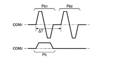
図4の駆動信号発生部64は、駆動信号COM1および駆動信号COM2を生成する。駆動信号COM1および駆動信号COM2の各々は、記録周期を1周期として各圧電振動子422を駆動する周期信号である。図5に示すように、駆動信号COM1の記録周期内には、圧電振動子422に供給された場合に圧力室50内のインクをノズルNから噴射させる噴射パルスPD1と噴射パルスPD2とが配置される。他方、駆動信号COM2の記録周期内には、圧力室50内のインクがノズルNから噴射されない程度の微振動を圧力室50内に付与する微振動パルスPSが配置される。
The
圧電振動子422に対する噴射パルスPD1の供給でノズルNからインク滴が噴射される時点t1と、圧電振動子422に対する噴射パルスPD2の供給でノズルNからインク滴が噴射される時点t2とが時間差ΔTだけ前後する(時点t2が時点t1に対して時間差ΔTだけ先行または遅延する)ように、噴射パルスPD1と噴射パルスPD2とは時間軸上の相異なる位置に配置される。具体的には、図5に示すように、噴射パルスPD1の始点と噴射パルスPD2の始点とは時間差ΔTだけ相違する。なお、第1実施形態では噴射パルスPD1と噴射パルスPD2とで波形が共通する場合を想定する。
A time difference ΔT between a time point t1 when the ink droplet is ejected from the nozzle N by the supply of the ejection pulse PD1 to the
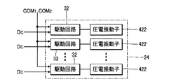
図6は、記録ヘッド24の電気的な構成の模式図である。図6に示すように、記録ヘッド24は、相異なる圧力室50に対応する複数の駆動回路32を含む。駆動信号発生部64が生成した駆動信号COM1および駆動信号COM2は、内部I/F68を介して複数の駆動回路32に共通に供給される。また、制御部60が生成した制御データDCは内部I/F68を介して各駆動回路32に供給される。
FIG. 6 is a schematic diagram of an electrical configuration of the
各駆動回路32は、制御部60から供給される制御データDCに応じた区間(PD1/PD2/PS)を駆動信号COM1または駆動信号COM2から選択して圧電振動子422に供給する。具体的には、駆動回路32は、時点t1でのインク滴の噴射を制御データDCが指示する場合には駆動信号COM1の噴射パルスPD1を選択して圧電振動子422に供給し、時点t2でのインク滴の噴射を制御データDCが指示する場合には駆動信号COM1の噴射パルスPD2を選択して圧電振動子422に供給する。したがって、各ノズル列28内で相互に隣り合う第1ノズルN1および第2ノズルN2の片方のみについてインク滴の噴射が必要な場合には時点t1でそのノズルNからインク滴が噴射され、第1ノズルN1および第2ノズルN2の双方からのインク滴の噴射が必要な場合には、例えば第1ノズルN1から時点t1でインク滴が噴射され、かつ、時点t1に対して時間差ΔTの時点t2で第2ノズルN2からインク滴が噴射される。他方、制御データDCがインク滴に非噴射を指示する場合、駆動回路32は、駆動信号COM2の微振動パルスPSを選択して圧電振動子422に供給する。したがって、圧力室50に微振動が付与され、圧力室50内のインクは噴射されずに適度に撹拌される。
Each
図7は、記録ヘッド24の各ノズルNから噴射されるインク滴が記録紙200の表面に着弾する様子の模式図である。なお、図2の例示のように実際には複数のノズル列28(28K,28Y,28M,28C)が記録ヘッド24に形成されるが、図7では便宜的に1個のノズル列28のみが図示されている。図7に示すように、記録ヘッド24の吐出面26と記録紙200の表面とは間隔Gをあけて相互に対向する。制御部60は、記録ヘッド24が固定されたキャリッジ12を記録紙200に対して速度VCRでX方向に相対的に移動させながら、各圧電振動子422を振動させることで各ノズル列28の複数のノズルN(N1,N2)からインク滴を噴射させる。各ノズルNから噴射されたインク滴は吐出面26と記録紙200との間隙を飛翔し、記録紙200の表面に着弾してドット(画素)を形成する。
FIG. 7 is a schematic diagram showing how ink droplets ejected from the nozzles N of the
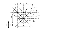
図8は、第1ノズルN1から時点t1にて噴射されたインク滴で形成されるドットD1と第2ノズルN2から時点t2にて噴射されたインク滴で形成されるドットD2との平面的な位置関係を示す模式図である。なお、以下ではドットD1とドットD2とが相等しい直径φの円形状である場合を想定する。 FIG. 8 is a plan view of dots D1 formed from ink droplets ejected from the first nozzle N1 at time t1 and dots D2 formed from ink droplets ejected from the second nozzle N2 at time t2. It is a schematic diagram which shows a positional relationship. In the following, it is assumed that the dots D1 and D2 have a circular shape with the same diameter φ.
記録ヘッド24(キャリッジ12)は記録紙200に対してX方向に移動するから、時点t1と時点t2との時間差ΔTが長いほど、ドットD1とドットD2とのX方向における中心間の距離は増加する。各ノズルNから噴射された各インク滴を充分に離間させるには時間差ΔTを充分に確保する必要があるが、時間差ΔTを過度に長い時間に設定することでドットD1とドットD2とが平面視で相互に離間すると、記録紙200に形成される画像の品質を低下させる原因となる。そこで、第1実施形態では、時点t1と時点t2との時間差ΔTを、ドットD1とドットD2とを記録紙200上で接触させ得る範囲内での最大値(すなわち、ドットD1とドットD2とが外接する数値)に設定する。
Since the recording head 24 (carriage 12) moves in the X direction with respect to the
図8や以下の数式(1)で表現されるように、ドットD1のX方向の位置x1からX方向の両側に距離δだけ離間した位置にドットD2の中心が位置する場合にドットD1とドットD2とが接触(外接)すると仮定する。
x2=x1±δ ……(1)
ドットD1とドットD2とが接触する場合、ドットD1とドットD2との中心間の距離は各々の直径φに合致する。いま、Y方向におけるドットD1とドットD2との中心間の距離(Y方向における第1ノズルN1と第2ノズルN2との中心間の距離d)を距離φ/√2とすると、ドットD1とドットD2とのX方向の中心間の距離δ(数式(1))は、直径φに応じた距離φ/√2で表現される。
As shown in FIG. 8 and the following formula (1), when the center of the dot D2 is located at a position spaced by a distance δ on both sides in the X direction from the position x1 in the X direction of the dot D1, the dot D1 and the dot D1 Assume that D2 is in contact (external).
x2 = x1 ± δ (1)
When the dots D1 and D2 come into contact with each other, the distance between the centers of the dots D1 and D2 matches each diameter φ. Now, assuming that the distance between the centers of the dots D1 and D2 in the Y direction (the distance d between the centers of the first nozzle N1 and the second nozzle N2 in the Y direction) is a distance φ / √2, the dots D1 and D2 A distance δ (formula (1)) between the center in the X direction and D2 is expressed by a distance φ / √2 corresponding to the diameter φ.
次に、第1ノズルN1から時点t1で噴射されたインク滴が形成するドットD1の中心の位置x1(図7の部分(B))と、第2ノズルN2から時点t2で噴射されたインク滴が形成するドットD2の中心の位置x2(図7の部分(C))とを検討する。位置x1および位置x2は、図7の部分(A)に示すように、所定の時点(以下「基準時点」という)t0での各ノズルNのX方向の位置を基準(x=0)とした位置である。また、図7の部分(B)に示すように、第1ノズルN1から噴射されたインク滴が飛翔速度V1で記録紙200に向けて飛翔し、図7の部分(C)に示すように、第2ノズルN2から噴射されたインク滴が飛翔速度V2で記録紙200に向けて飛翔する場合を想定する。飛翔速度V1および飛翔速度V2は、各ノズルN(N1,N2)での噴射から記録紙200に着弾するまでの平均速度である。
Next, the center position x1 (part (B) of FIG. 7) of the dot D1 formed by the ink droplet ejected from the first nozzle N1 at time t1, and the ink droplet ejected from the second nozzle N2 at time t2. And the center position x2 (part (C) of FIG. 7) of the dot D2 formed by. As shown in the part (A) of FIG. 7, the position x1 and the position x2 are based on the position of each nozzle N in the X direction at a predetermined time point (hereinafter referred to as “reference time point”) t0 (x = 0). Position. Further, as shown in part (B) of FIG. 7, ink droplets ejected from the first nozzle N1 fly toward the
図7の部分(B)から理解されるように、第1ノズルN1がインク滴を噴射する時点t1から記録紙200に着弾するまでに時間(G/V1)が経過する。したがって、基準時点t0から時間T1が経過した時点t1で第1ノズルN1からインク滴が噴射された場合、基準時点t0からインク滴の着弾までに経過する時間τ1は、以下の数式(2)で表現される。
τ1=(G/V1)+T1 ……(2)
同様に、基準時点t0から時間T2が経過した時点t2で第2ノズルN2からインク滴が噴射された場合、基準時点t0からインク滴の着弾までに経過する時間τ2は以下の数式(3)で表現される。
τ2=(G/V2)+T2 ……(3)
As understood from the part (B) of FIG. 7, time (G / V1) elapses from the time point t1 when the first nozzle N1 ejects the ink droplet to the time when it reaches the
τ1 = (G / V1) + T1 (2)
Similarly, when an ink droplet is ejected from the second nozzle N2 at the time t2 when the time T2 has elapsed from the reference time t0, the time τ2 that elapses from the reference time t0 to the landing of the ink droplet is expressed by the following equation (3). Expressed.
τ2 = (G / V2) + T2 (3)
数式(1)の時間τ1内に記録紙200が記録ヘッド24に対してX方向に速度VCRで相対的に移動するから、ドットD1の位置x1は以下の数式(4)で表現される。
x1={(G/V1)+T1}・VCR ……(4)
同様に、ドットD2の位置x2を表現する以下の数式(5)が導出される。
x2={(G/V2)+T2}・VCR ……(5)
数式(4)および数式(5)を数式(1)に代入すると以下の数式(6)が導出される。
{(G/V2)+T2}・VCR−{(G/V1)+T1}・VCR=±δ ……(6)
Since the
x1 = {(G / V1) + T1} · VCR (4)
Similarly, the following formula (5) expressing the position x2 of the dot D2 is derived.
x2 = {(G / V2) + T2} .VCR (5)
Substituting Equations (4) and (5) into Equation (1) yields Equation (6) below.
{(G / V2) + T2} · VCR − {(G / V1) + T1} · VCR = ± δ (6)
時点t1と時点t2との時間差ΔT(ΔT=T2−T1,T2=ΔT+T1)を数式(6)に代入すると以下の数式(7)が導出される。
{(G/V2)+(ΔT+T1)}・VCR−{(G/V1)+T1}・VCR=±δ
ΔT={(V2−V1)/(V1・V2)}・G±δ/VCR ……(7)
Substituting the time difference ΔT (ΔT = T2−T1, T2 = ΔT + T1) between the time point t1 and the time point t2 into the equation (6), the following equation (7) is derived.
{(G / V2) + (ΔT + T1)} · VCR − {(G / V1) + T1} · VCR = ± δ
ΔT = {(V2−V1) / (V1 ・ V2)} ・ G ± δ / VCR (7)
第1実施形態では噴射パルスPD1と噴射パルスPD2とで波形が共通するから、第1ノズルN1からのインク滴の飛翔速度V1と第2ノズルN2からのインク滴の飛翔速度V2とは相等しい(V1=V2)。したがって、ドットD1とドットD2とが接触する場合の時点t1と時点t2との時間差ΔTを表現する以下の数式(8)が導出される。数式(8)の距離δは、図8を参照して説明したように例えば距離φ/√2に設定される。
ΔT=±δ/VCR ……(8)
In the first embodiment, since the ejection pulse PD1 and the ejection pulse PD2 have the same waveform, the flying speed V1 of the ink droplet from the first nozzle N1 and the flying speed V2 of the ink droplet from the second nozzle N2 are equal ( V1 = V2). Therefore, the following formula (8) expressing the time difference ΔT between the time point t1 and the time point t2 when the dot D1 and the dot D2 are in contact is derived. The distance δ in the equation (8) is set to, for example, the distance φ / √2 as described with reference to FIG.
ΔT = ± δ / VCR (8)
噴射パルスPD1の供給でインク滴が噴射する時点t1と噴射パルスPD2の供給でインク滴が噴射する時点t2との時間差(例えば噴射パルスPD1の始点と噴射パルスPD2の始点との時間差)ΔTが数式(8)を充足するように駆動信号COM1が生成される。すなわち、第2ノズルN2からのインク滴の噴射時点t2は、第1ノズルN1からのインク滴の噴射時点t1に対して時間(δ/VCR)だけ先行または遅延する。 ΔT is the time difference between the time t1 when the ink droplet is ejected by the supply of the ejection pulse PD1 and the time t2 when the ink droplet is ejected by the supply of the ejection pulse PD2 (eg, the time difference between the start point of the ejection pulse PD1 and the start point of the ejection pulse PD2). The drive signal COM1 is generated so as to satisfy (8). That is, the ink droplet ejection time t2 from the second nozzle N2 precedes or delays the time (δ / VCR) with respect to the ink droplet ejection time t1 from the first nozzle N1.
以上に説明した第1実施形態では、相異なる時点(t1,t2)で第1ノズルN1および第2ノズルN2の各々からインク滴が噴射されるため、各ノズルNから同時にインク滴が噴射される構成と比較して、各ノズルNから記録紙200に向けて飛翔するインク滴の間隔が充分に確保される。したがって、吐出面26から記録紙200にわたるエアカーテンの影響が低減され、着弾位置の誤差(着弾範囲が所期の範囲よりも広範囲に拡大する現象)や吐出面26に対するミストの付着を抑制することが可能である。また、ドットD1とドットD2とが平面視で接触(外接)するように時間差ΔTが選定される。したがって、着弾位置の誤差やミストの付着等が有効に抑制されるように時間差ΔTを確保しながら、ドットD1とドットD2との離間に起因した画質の低下を抑制することが可能である。
In the first embodiment described above, since ink droplets are ejected from each of the first nozzle N1 and the second nozzle N2 at different times (t1, t2), ink droplets are ejected simultaneously from each nozzle N. Compared with the configuration, a sufficient interval between ink droplets flying from each nozzle N toward the
<B:第2実施形態>
本発明の第2実施形態を以下に説明する。第1実施形態では、各ノズルNからインク滴が噴射する時点を第1ノズルN1と第2ノズルN2とで相違させた。第2実施形態では、第1ノズルN1と第2ノズルN2とでインク滴を同時に噴射させる一方、第1ノズルN1から噴射されたインク滴の飛翔速度V1と第2ノズルN2から噴射されたインク滴の飛翔速度V2とが相違するように制御部60が記録ヘッド24を制御する。なお、以下に例示する各態様において作用や機能が第1実施形態と同等である要素については、以上の説明で参照した符号を流用して各々の詳細な説明を適宜に省略する。
<B: Second Embodiment>
A second embodiment of the present invention will be described below. In the first embodiment, the time point at which ink droplets are ejected from each nozzle N is different between the first nozzle N1 and the second nozzle N2. In the second embodiment, ink droplets are simultaneously ejected by the first nozzle N1 and the second nozzle N2, while the flying speed V1 of the ink droplet ejected from the first nozzle N1 and the ink droplet ejected from the second nozzle N2. The
第2実施形態の制御部60は、第1実施形態と同様に、Y方向に相互に隣り合う第1ノズルN1および第2ノズルN2をノズル列28から選択する組合せ毎に、第1ノズルN1および第2ノズルN2からのインク滴の噴射の要否を印刷データDPに応じて判定する。そして、制御部60は、第1ノズルN1および第2ノズルN2のうち片方のみについてインク滴の噴射が必要な場合にはそのノズルNから飛翔速度V1でインク滴が噴射され、第1ノズルN1および第2ノズルN2の双方からのインク滴の噴射が必要な場合には、第1ノズルN1から飛翔速度V1でインク滴が噴射されるとともに第2ノズルN2から飛翔速度V2でインク滴が噴射されるように記録ヘッド24を制御する。すなわち、飛翔速度V1でのインク滴の噴射と飛翔速度V2でのインク滴の噴射とインク滴の非噴射(微振動)との何れかを指示する制御データDCを印刷データDPに応じて生成する。
As in the first embodiment, the
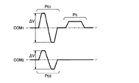
図9は、駆動信号COM1および駆動信号COM2の波形図である。図9に示すように、駆動信号COM1には噴射パルスPD1と微振動パルスPSとが配置され、駆動信号COM2には噴射パルスPD2が配置される。噴射パルスPD1の供給でノズルNから噴射されるインク滴の飛翔速度V1と噴射パルスPD2の供給でノズルNから噴射されるインク滴の飛翔速度V2とが相違するように、噴射パルスPD1と噴射パルスPD2とは相異なる波形に設定される。具体的には、図9に示す電位変動幅ΔV(更には電位の時間変化率)が噴射パルスPD1と噴射パルスPD2とで相違する。なお、各ノズルNからインク滴が噴射される時点は噴射パルスPD1と噴射パルスPD2とで実質的に同時である。
FIG. 9 is a waveform diagram of the drive signal COM1 and the drive signal COM2. As shown in FIG. 9, the ejection pulse PD1 and the minute vibration pulse PS are arranged in the drive signal COM1, and the ejection pulse PD2 is arranged in the drive signal COM2. The ejection pulse PD1 and the ejection pulse are different so that the flying speed V1 of the ink droplet ejected from the nozzle N by the supply of the ejection pulse PD1 is different from the flying speed V2 of the ink droplet ejected from the nozzle N by the supply of the ejection pulse PD2. A waveform different from PD2 is set. Specifically, the potential fluctuation range ΔV (and the time change rate of the potential) shown in FIG. 9 is different between the ejection pulse PD1 and the ejection pulse PD2. The time point at which the ink droplet is ejected from each nozzle N is substantially the same for the ejection pulse PD1 and the ejection pulse PD2.
記録ヘッド24の各駆動回路32は、飛翔速度V1でのインク滴の噴射を制御データDCが指示する場合には駆動信号COM1の噴射パルスPD1を選択して圧電振動子422に供給し、飛翔速度V2でのインク滴の噴射を制御データDCが指示する場合には駆動信号COM2の噴射パルスPD2を選択して圧電振動子422に供給する。したがって、各ノズル列28内で相互に隣り合う第1ノズルN1および第2ノズルN2の片方のみについてインク滴の噴射が必要な場合にはそのノズルNから飛翔速度V1でインク滴が噴射され、第1ノズルN1および第2ノズルN2の双方からのインク滴の噴射が必要な場合には、例えば第1ノズルN1から飛翔速度V1でインク滴が噴射されるとともに第2ノズルN2から飛翔速度V2でインク滴が噴射される。例えば、印刷データDPが示す画像の形成に各ノズル列28の全部のノズルNからのインク滴の噴射が必要である場合、奇数番目の各ノズルN(第1ノズルN1)から飛翔速度V1でインク滴が噴射されるとともに偶数番目の各ノズルN(第2ノズルN2)から飛翔速度V2でインク滴が噴射される。
Each
飛翔速度V1で飛翔するインク滴と飛翔速度V2で飛翔するインク滴との間隔は、各ノズルNから同時に噴射されて記録紙200に接近するにつれて拡大するから、第2実施形態でも第1実施形態と同様に、各ノズルNから相等しい飛翔速度で同時にインク滴が噴射される構成と比較して、各インク滴の接近に起因した着弾位置の誤差やミストの付着を抑制できるという効果が実現される。
Since the interval between the ink droplets flying at the flying speed V1 and the ink droplets flying at the flying speed V2 is simultaneously ejected from the nozzles N and becomes closer to the
ところで、飛翔速度V1と飛翔速度V2との差異が大きいほど、各ノズルNから噴射されたインク滴を充分に離間させる(したがって着弾位置の誤差やミストの付着を抑制するという効果を強化する)ことが可能である。ただし、飛翔速度V1と飛翔速度V2とを過度に相違させると、ドットD1とドットD2とが平面視で相互に離間して画像の品質を低下させる原因となる。そこで、第2実施形態では、以下に詳述するようにドットD1とドットD2とが記録紙200上で接触するように飛翔速度V1と飛翔速度V2とを設定する。
By the way, the larger the difference between the flying speed V1 and the flying speed V2, the more sufficiently the ink droplets ejected from the nozzles N are separated (thus enhancing the effect of suppressing landing position errors and mist adhesion). Is possible. However, if the flying speed V1 and the flying speed V2 are excessively different from each other, the dots D1 and D2 are separated from each other in a plan view, which causes a reduction in image quality. Therefore, in the second embodiment, the flying speed V1 and the flying speed V2 are set so that the dots D1 and D2 are in contact with each other on the
飛翔速度V1と飛翔速度V2との関係を以下の数式(9)のように定義する。すなわち、定数αは、飛翔速度V1に対する飛翔速度V2の相対比を意味する。
V2=α・V1 ……(9)
前掲の数式(7)において時間差ΔTをゼロに設定する(すなわち第1ノズルN1と第2ノズルN2とが同時にインク滴を噴射する)とともに数式(7)に数式(9)を代入することで以下の数式(10)が導出される。
0={(α・V1−V1)/(V1・α・V1)}・G±δ/VCR
α=G・VCR/(±δ・V1+G・VCR) ……(10)
飛翔速度V1に対する飛翔速度V2の相対比αが数式(10)を充足するように(すなわちドットD1とドットD2とが平面視で接触するように)、噴射パルスPD1および噴射パルスPD2の各々の波形が選定される。したがって、第1実施形態と同様に、着弾位置の誤差やミストの付着の低減という効果を確保しながら、ドットD1とドットD2との離間に起因した画質の低下を抑制することが可能である。
The relationship between the flying speed V1 and the flying speed V2 is defined as the following formula (9). That is, the constant α means a relative ratio of the flying speed V2 to the flying speed V1.
V2 = α ・ V1 (9)
By substituting the formula (9) into the formula (7) while setting the time difference ΔT to zero in the above formula (7) (that is, the first nozzle N1 and the second nozzle N2 simultaneously eject ink droplets). Equation (10) is derived.
0 = {(α ・ V1−V1) / (V1 ・ α ・ V1)} ・ G ± δ / VCR
α = G ・ VCR / (± δ ・ V1 + G ・ VCR) ...... (10)
Each waveform of the ejection pulse PD1 and the ejection pulse PD2 so that the relative ratio α of the flight speed V2 to the flight speed V1 satisfies the formula (10) (that is, the dots D1 and D2 are in contact in plan view). Is selected. Therefore, as in the first embodiment, it is possible to suppress a decrease in image quality due to the separation between the dots D1 and D2, while ensuring the effect of reducing landing position errors and mist adhesion.
<C:第3実施形態>
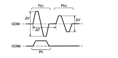
図10は、第3実施形態における駆動信号COM1および駆動信号COM2の波形図である。駆動信号COM1には噴射パルスPD1と噴射パルスPD2とが配置される。噴射パルスPD1と噴射パルスPD2とは時間軸上の相異なる位置(時間差ΔT)に配置されて波形(電位変動幅ΔV)が相違する。したがって、噴射パルスPD1の供給で各ノズルNからインク滴が噴射される時点t1および飛翔速度V1と、噴射パルスPD2の供給で各ノズルNからインク滴が噴射される時点t2および飛翔速度V2とは相違する。駆動信号COM2は第1実施形態と同様である。
<C: Third Embodiment>
FIG. 10 is a waveform diagram of the drive signal COM1 and the drive signal COM2 in the third embodiment. An ejection pulse PD1 and an ejection pulse PD2 are arranged in the drive signal COM1. The ejection pulse PD1 and the ejection pulse PD2 are arranged at different positions (time difference ΔT) on the time axis and have different waveforms (potential fluctuation width ΔV). Therefore, the time point t1 and the flying speed V1 at which the ink droplets are ejected from each nozzle N by the supply of the ejection pulse PD1, and the time point t2 and the flying speed V2 at which the ink droplets are ejected from the nozzles N by the supply of the ejection pulse PD2. Is different. The drive signal COM2 is the same as that in the first embodiment.
第1ノズルN1および第2ノズルN2の片方のみについてインク滴の噴射が必要な場合には、噴射パルスPD1の供給により時点t1にて飛翔速度V1のインク滴がそのノズルNから噴射されるように、制御部60は記録ヘッド24を制御する。また、第1ノズルN1および第2ノズルN2の双方からのインク滴の噴射が必要な場合には、例えば噴射パルスPD1の供給により第1ノズルN1から時点t1で飛翔速度V1のインク滴が噴射され、かつ、噴射パルスPD2の供給により第2ノズルN2から時点t2で飛翔速度V2のインク滴が噴射されるように、制御部60は記録ヘッド24を制御する。
When it is necessary to eject ink droplets for only one of the first nozzle N1 and the second nozzle N2, an ink droplet having a flying speed V1 is ejected from the nozzle N at time t1 by supplying the ejection pulse PD1. The
前掲の数式(9)を数式(7)に代入すると以下の数式(11)が導出される。
ΔT={(α・V1−V1)/(V1・α・V1)}・G±δ/VCR
ΔT={(α−1)/α}・(G/V1)±δ/VCR ……(11)
時点t1と時点t2との時間差ΔTおよび飛翔速度V1と飛翔速度V2との相対比αが数式(11)の関係を充足するように(すなわち、ドットD1とドットD2とが平面視で接触するように)、駆動信号COM1が生成される。したがって、第3実施形態においても第1実施形態や第2実施形態と同様の効果が実現される。
Substituting Equation (9) above into Equation (7) yields Equation (11) below.
ΔT = {(α ・ V1−V1) / (V1 ・ α ・ V1)} ・ G ± δ / VCR
ΔT = {(α-1) / α} · (G / V1) ± δ / VCR (11)
The time difference ΔT between the time point t1 and the time point t2 and the relative ratio α between the flying speed V1 and the flying speed V2 satisfy the relationship of Equation (11) (that is, the dots D1 and D2 are in contact in plan view). ), The drive signal COM1 is generated. Therefore, also in the third embodiment, the same effect as the first embodiment and the second embodiment is realized.
<D:変形例>
以上の各形態は多様に変形される。具体的な変形の態様を以下に例示する。以下の例示から任意に選択された2以上の態様は適宜に併合され得る。
<D: Modification>
Each of the above forms can be variously modified. Specific modifications are exemplified below. Two or more aspects arbitrarily selected from the following examples can be appropriately combined.
(1)変形例1
以上の各形態では、相互に隣り合う2個のノズルN(N1,N2)についてインク滴の噴射の時点(t1,t2)や飛翔速度(V1,V2)を相違させたが、複数のノズルNを更に高密度に配列した場合、例えば第1番目のノズルNから噴射されるインク滴と第3番目以降のノズルNから噴射されるインク滴とが接近することで着弾位置の誤差やミストの付着等の問題(以下では「液滴接近問題」と総称する)が発生する可能性がある。したがって、相互に共通の噴射条件でインク滴を噴射した場合に液滴接近問題が顕在化する範囲内に位置する複数のノズルNの各々について噴射条件を相違させる構成が好適である。なお、以下の説明では、インク滴の噴射条件が共通する2個のノズルNの中心間の距離が所定距離(以下「限界距離」という)を下回る場合に液滴接近問題が顕在化すると仮定する。すなわち、中心間の距離が限界距離を上回るほど2個のノズルNが離間するならば、噴射条件を共通させた場合でも液滴接近問題は実質的に顕在化しない。例えば、限界距離は、600dpiの解像度に対応する数値に設定される。
(1)
In each of the above embodiments, the ink droplet ejection time (t1, t2) and the flying speed (V1, V2) are different for the two nozzles N (N1, N2) adjacent to each other. Are arranged at a higher density, for example, when the ink droplets ejected from the first nozzle N and the ink droplets ejected from the third and subsequent nozzles N approach each other, landing position errors and mist adhesion (Hereinafter collectively referred to as “droplet approach problem”). Therefore, a configuration in which the ejection conditions are different for each of the plurality of nozzles N located within a range where the droplet approach problem becomes apparent when ink droplets are ejected under mutually common ejection conditions is preferable. In the following description, it is assumed that the droplet approach problem becomes apparent when the distance between the centers of the two nozzles N that share the same ink droplet ejection condition is below a predetermined distance (hereinafter referred to as “limit distance”). . That is, if the two nozzles N are separated such that the distance between the centers exceeds the limit distance, the droplet approach problem does not substantially manifest even when the ejection conditions are made common. For example, the limit distance is set to a numerical value corresponding to a resolution of 600 dpi.
図11に例示するように、Y方向に相互に隣り合うK個(Kは2以上の自然数)のノズルN[1]〜N[K]を単位としてノズル列28をM個のブロックB[1]〜B[M]に区分した場合を想定する。相互に隣り合うブロックB[m1]とブロックB[m2]とに着目した場合(m1≠m2)に、ブロックB[m1]内の第k番目(k=1〜K)のノズルN[k]とブロックB[m2]内のノズルN[k]との中心間の距離が前述の限界距離を上回るように、各ブロックB[m](m=1〜M)のノズルN[k]の個数Kが選定される。他方、ブロックB[m]内で両端に位置するノズルN[1]とノズルN[K]との中心間の距離は限界距離を下回る。すなわち、1個のブロックB[m]内のノズルN[1]とノズルN[K]とで噴射条件が共通する場合には各インク滴の接近に起因した液滴接近問題が顕在化する。
As illustrated in FIG. 11, the
以上の条件のもとでは、各ブロックB[m]内のK個のノズルN[1]〜N[K]の各々でインク滴の噴射条件(噴射時点や飛翔速度)を相違させた構成が好適である。例えば、各ノズルN[k]からインク滴が噴射される時点tkやインク滴の飛翔速度Vkが各ブロックB[m]内のK個のノズルN[1]〜N[K]の各々で相違するように、制御部60は記録ヘッド24を制御する。M個のブロックB[1]〜B[M]の各々の第k番目のノズルN[k]の噴射条件は共通する。ただし、前述の各形態と同様に、1個のノズル列28の複数(M×K個)のノズルNから噴射されたインク滴で記録紙200に形成されるドットが相互に接触または重複するように、各ノズルN[k]の噴射条件が選定される。
Under the above conditions, a configuration in which each of the K nozzles N [1] to N [K] in each block B [m] has different ink droplet ejection conditions (ejecting time and flying speed). Is preferred. For example, the time point tk at which the ink droplet is ejected from each nozzle N [k] and the flying speed Vk of the ink droplet are different for each of the K nozzles N [1] to N [K] in each block B [m]. As described above, the
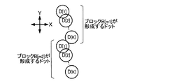
例えば、各ブロックB[m]内のK個のノズルN[1]〜N[K]の配列の順番(N[1]→N[2]→……→N[K])で順次にインク滴を噴射する構成(飛翔速度V1〜VKは共通)では、図12に示すように、ブロックB[m1]の一方の端部のノズルN[K]から噴射されたインク滴で形成されるドットD[K]と、ブロックB[m2]の他方の端部のノズルN[1]から噴射されたインク滴で形成されるドットD[1]とが平面視で間隔σをあけて相互に離間する可能性がある。そこで、図13に示すようにドットD[K]とドットD[1]とが相互に接触または重複するように各ノズルN[k]からのインクの噴射条件が選定される。具体的には、各ブロックB[m]のノズルN[1]からインク滴を噴射させる時点t1と各ブロックB[m]のノズルN[K]からインク滴を噴射させる時点tKとの時間差ΔTが数式(8)を充足するように各ノズルN[k]の噴射条件が選定される。したがって、1個のノズル列28の複数(M×K個)のノズルNが形成するドットDは相互に接触または重複する。
For example, ink is sequentially printed in the order of arrangement of K nozzles N [1] to N [K] in each block B [m] (N [1] → N [2] → …… → N [K]). In the configuration in which droplets are ejected (flight speeds V1 to VK are common), dots formed by ink droplets ejected from the nozzle N [K] at one end of the block B [m1] as shown in FIG. D [K] and the dot D [1] formed by the ink droplet ejected from the nozzle N [1] at the other end of the block B [m2] are spaced apart from each other with a spacing σ in plan view. there's a possibility that. Therefore, as shown in FIG. 13, the ink ejection conditions from each nozzle N [k] are selected so that the dots D [K] and D [1] are in contact with each other or overlap each other. Specifically, the time difference ΔT between the time point t1 at which the ink droplet is ejected from the nozzle N [1] of each block B [m] and the time point tK at which the ink droplet is ejected from the nozzle N [K] of each block B [m]. Is selected so that the nozzle N [k] satisfies the formula (8). Therefore, the dots D formed by a plurality (M × K) of nozzles N in one
(2)変形例2
以上の各形態では、記録ヘッド24を搭載したキャリッジ12がX方向(主走査方向)に移動するシリアル型の印刷装置100を例示したが、図14に示すように、記録紙200の幅方向の全域に対向するように各ノズル列28の複数のノズルNが配列されたライン型の記録ヘッド24を利用した印刷装置にも本発明を適用することが可能である。なお、図14では便宜的に1個のノズル列28のみを図示したが、相異なるインク色に対応する複数のノズル列28(28K,28Y,28M,28C)が実際には形成される。
(2)
In each of the above embodiments, the serial
記録ヘッド24は固定され、記録紙200をY方向に搬送させながら各ノズルNからインクを噴射することで記録紙200に画像が記録される。以上の説明から理解されるように、記録紙200(着弾対象)に対して記録ヘッド24が相対的に移動する構成に本発明は好適に適用され、記録ヘッド24自体の可動/固定は本発明において不問である。
The
(3)変形例3
以上の各形態ではドットD(D1,D2)の直径φを利用して時点t1と時点t2との時間差ΔT(数式(8))や飛翔速度V1と飛翔速度V2との相対比α(数式(10))を規定したが、直径φを解像度R(dpi:dot per inch)に置換することも可能である。直径φは、解像度Rを含む以下の数式(12)で表現される。
φ=(2.54×10²/R)×√2 ……(12)
(3) Modification 3
In each of the above embodiments, the time difference ΔT (formula (8)) between the time point t1 and the time point t2 using the diameter φ of the dot D (D1, D2) and the relative ratio α (formula ( Although 10)) is specified, it is possible to replace the diameter φ with the resolution R (dpi: dot per inch). The diameter φ is expressed by the following formula (12) including the resolution R.
φ = (2.54 × 10 2 / R) × √2 (12)
数式(8)の距離δを前述のように距離φ/√2とすれば(δ=φ/√2=2.54×102/R)、数式(12)を数式(8)に代入することで以下の数式(8a)が導出される。
ΔT=±(2.54×10²)/(R・VCR) ……(8a)
Assuming that the distance δ in the equation (8) is the distance φ / √2 as described above (δ = φ / √2 = 2.54 × 10 2 / R), the equation (12) is substituted into the equation (8). The following formula (8a) is derived.
ΔT = ± (2.54 × 10 2 ) / (R ・ VCR) ...... (8a)
同様に、前掲の数式(10)は以下の数式(10a)に変形され、数式(11)は数式(11a)に変形される。
α=G・VCR/{±(2.54×102/R)・V1+G・VCR} ……(10a)
ΔT={(α−1)/α}・(G/V1)±(2.54×102)/(R・VCR) ……(11a)
以上に説明した数式(数式(8a),数式(10a),数式(11a))を充足するように各ノズルNからのインク滴の噴射条件を選定した構成も採用され得る。
Similarly, the mathematical formula (10) is transformed into the following mathematical formula (10a), and the mathematical formula (11) is transformed into the mathematical formula (11a).
α = G ・ VCR / {± (2.54 × 10 2 / R) ・ V1 + G ・ VCR} (10a)
ΔT = {(α-1) / α} · (G / V1) ± (2.54 × 10 2 ) / (R · VCR) (11a)
A configuration in which the ink droplet ejection conditions from each nozzle N are selected so as to satisfy the mathematical expressions described above (Mathematical Expression (8a), Numerical Expression (10a), and Numerical Expression (11a)) may be employed.
(4)変形例4
以上の各形態では、駆動信号COM1および駆動信号COM2を記録ヘッド24に供給したが、1系統の駆動信号を各圧電振動子422の駆動に使用する構成や、3系統以上の駆動信号を各圧電振動子422の駆動に使用する構成も採用され得る。また、駆動信号の各パルス(PD1,PD2,PS)の波形は任意である。
(4) Modification 4
In each of the above embodiments, the drive signal COM1 and the drive signal COM2 are supplied to the
(5)変形例5
以上の各形態では縦振動型の圧電振動子422を例示したが、圧力室50内の圧力を変化させる要素(圧力発生素子)の構成は以上の例示に限定されない。例えば、撓み振動型の圧電振動子や静電アクチュエーター等の振動体を利用することも可能である。また、圧力発生素子は、圧力室50に機械的な振動を付与する要素に限定されない。例えば、圧力室50の加熱で気泡を発生させて圧力室50内の圧力を変化させる発熱素子(ヒーター)を圧力発生素子として利用することも可能である。すなわち、圧力発生素子は、圧力室50内の圧力を変化させる要素として包括され、圧力を変化させる方法(ピエゾ方式/サーマル方式)や構成の如何は不問である。
(5) Modification 5
In each of the above embodiments, the longitudinal vibration type
(6)変形例6
以上の各形態の印刷装置100は、プロッターやファクシミリ装置,コピー機等の各種の機器に採用され得る。もっとも、本発明の液体噴射装置の用途は画像の印刷に限定されない。例えば、各色材の溶液を噴射する液体噴射装置は、液晶表示装置のカラーフィルターを形成する製造装置として利用される。また、液体状の導電材料を噴射する液体噴射装置は、例えば有機EL(Electroluminescence)表示装置や電界放出表示装置(FED:Field Emission Display)等の表示装置の電極を形成する電極製造装置として利用される。また、生体有機物の溶液を噴射する液体噴射装置は、生物科学素子(バイオチップ)を製造するチップ製造装置として利用される。そして、液体の噴射の目標となる物体(着弾対象)は液体噴射装置の用途に応じて相違する。具体的には、前述の印刷装置100の着弾対象は記録紙200であるが、液体噴射装置を表示装置の製造に使用する場合には、例えば表示装置を構成する基板が着弾対象に相当する。
(6) Modification 6
The
100……印刷装置、12……キャリッジ、14……移動機構、16……用紙搬送機構、22……インクカートリッジ、24……記録ヘッド、26……吐出面、28(28K,28Y,28M,28C)……ノズル列、N(N1,N2)……ノズル、32……駆動回路、50……圧力室、52……供給路、54……貯留室、102……制御装置、104……印刷処理部、60……制御部、62……記憶部、64……駆動信号発生部、66……外部I/F、68……内部I/F、200……記録紙、300……外部装置。
DESCRIPTION OF
Claims (6)
前記複数のノズルの各々からの液体噴射を制御する制御手段とを具備する液体噴射装置であって、
前記制御手段は、前記複数のノズルのうち第1ノズルおよび第2ノズルからの液体噴射の要否を印刷データから判定し、前記第1ノズルおよび前記第2ノズルの双方からの液体噴射が必要な場合に、前記第1ノズルと前記第2ノズルとで液体の噴射条件を相違させる
液体噴射装置。 A liquid ejecting section capable of ejecting liquid from each nozzle of a nozzle row including a plurality of nozzles;
A liquid ejecting apparatus comprising control means for controlling the liquid ejection from each of the plurality of nozzles,
The control means determines whether or not liquid ejection from the first nozzle and the second nozzle among the plurality of nozzles is necessary from the print data, and requires liquid ejection from both the first nozzle and the second nozzle. In the case, a liquid ejecting apparatus in which liquid ejecting conditions are made different between the first nozzle and the second nozzle.
請求項1の液体噴射装置。 The liquid ejecting apparatus according to claim 1, wherein the control unit makes the time of liquid ejection different between the first nozzle and the second nozzle.
請求項1の液体噴射装置。 The liquid ejecting apparatus according to claim 1, wherein the control unit makes the velocity of the ejected liquid different between the first nozzle and the second nozzle.
請求項1から請求項3の何れかの液体噴射装置。 The liquid ejecting apparatus according to claim 1, wherein the second nozzle is a nozzle closest to the first nozzle.
前記第1ノズルから噴射された液体で前記着弾対象に形成される第1ドットと、前記第2ノズルから噴射された液体で前記着弾対象に形成される第2ドットとが、前記相対移動の方向について相互に接触または重複するように、前記第1ノズルおよび前記第2ノズルの各々における液体の噴射条件が選定されている
請求項1から請求項4の何れかの液体噴射装置。 A moving mechanism for moving the liquid ejecting unit relative to a landing target on which the liquid ejected from each nozzle lands,
The first dot formed on the landing target with the liquid ejected from the first nozzle and the second dot formed on the landing target with the liquid ejected from the second nozzle are in the direction of the relative movement. 5. The liquid ejecting apparatus according to claim 1, wherein liquid ejecting conditions in each of the first nozzle and the second nozzle are selected so as to contact or overlap each other.
前記複数のノズルのうち第1ノズルおよび第2ノズルからの液体噴射の要否を印刷データから判定し、
前記第1ノズルおよび前記第2ノズルの双方からの液体噴射が必要な場合に、前記第1ノズルと前記第2ノズルとで液体の噴射条件を相違させる
液体噴射装置の制御方法。
A control method for controlling liquid ejection from each of the plurality of nozzles for a liquid ejecting apparatus including a liquid ejecting unit capable of ejecting liquid from each of the plurality of nozzles,
Determining whether or not liquid ejection from the first nozzle and the second nozzle among the plurality of nozzles is necessary from print data;
A method for controlling a liquid ejecting apparatus, wherein when the liquid ejection from both the first nozzle and the second nozzle is necessary, the liquid ejecting conditions are made different between the first nozzle and the second nozzle.
Priority Applications (1)
| Application Number | Priority Date | Filing Date | Title |
|---|---|---|---|
| JP2010255590A JP2012106366A (en) | 2010-11-16 | 2010-11-16 | Liquid jet apparatus and control method therefor |
Applications Claiming Priority (1)
| Application Number | Priority Date | Filing Date | Title |
|---|---|---|---|
| JP2010255590A JP2012106366A (en) | 2010-11-16 | 2010-11-16 | Liquid jet apparatus and control method therefor |
Publications (1)
| Publication Number | Publication Date |
|---|---|
| JP2012106366A true JP2012106366A (en) | 2012-06-07 |
Family
ID=46492555
Family Applications (1)
| Application Number | Title | Priority Date | Filing Date |
|---|---|---|---|
| JP2010255590A Withdrawn JP2012106366A (en) | 2010-11-16 | 2010-11-16 | Liquid jet apparatus and control method therefor |
Country Status (1)
| Country | Link |
|---|---|
| JP (1) | JP2012106366A (en) |
-
2010
- 2010-11-16 JP JP2010255590A patent/JP2012106366A/en not_active Withdrawn
Similar Documents
| Publication | Publication Date | Title |
|---|---|---|
| US9764551B2 (en) | Ink-jet head and printer | |
| US8313160B2 (en) | Liquid ejecting apparatus | |
| JP2014042995A (en) | Liquid jet device, and control method for liquid jet device | |
| JP2019059131A (en) | Liquid discharge device | |
| US10906297B2 (en) | Liquid ejection device and image forming device | |
| US8764142B2 (en) | Liquid ejection apparatus and control method thereof | |
| JP2014111314A (en) | Liquid discharge head and liquid discharge device | |
| JP2012176574A (en) | Liquid ejecting apparatus and driving method thereof | |
| JP5299122B2 (en) | Droplet ejector | |
| US8388087B2 (en) | Liquid ejecting apparatus and method of controlling same | |
| EP3650225B1 (en) | Liquid ejection device and image forming device | |
| JP2012101379A (en) | Liquid ejecting apparatus | |
| JP2012106366A (en) | Liquid jet apparatus and control method therefor | |
| US20120139999A1 (en) | Liquid ejecting head and liquid ejecting apparatus | |
| JP2012111095A (en) | Liquid jet apparatus and control method thereof | |
| US20250360709A1 (en) | Droplet ejecting apparatus, control method of the same, and medium | |
| JP6451409B2 (en) | Liquid ejection device and method for controlling liquid ejection device | |
| JP2007152665A (en) | Liquid ejecting head and liquid ejecting apparatus | |
| JP2012111094A (en) | Liquid jet apparatus and control method thereof | |
| JP2004009549A (en) | Driving method of inkjet head and inkjet printer | |
| JP2018202640A (en) | Liquid ejecting apparatus and method for controlling liquid ejecting apparatus | |
| JP4595463B2 (en) | Inkjet printer | |
| JP2013184459A (en) | Liquid jetting device and control method thereof | |
| JP2017056639A (en) | Liquid ejecting apparatus, liquid ejecting method, control program for liquid ejecting apparatus, and recording medium | |
| JP2012161917A (en) | Liquid ejecting apparatus and control method of the same |
Legal Events
| Date | Code | Title | Description |
|---|---|---|---|
| A300 | Withdrawal of application because of no request for examination |
Free format text: JAPANESE INTERMEDIATE CODE: A300 Effective date: 20140204 |