JP2012107751A - Metal tube for thermal decomposition reaction - Google Patents
Metal tube for thermal decomposition reaction Download PDFInfo
- Publication number
- JP2012107751A JP2012107751A JP2011255020A JP2011255020A JP2012107751A JP 2012107751 A JP2012107751 A JP 2012107751A JP 2011255020 A JP2011255020 A JP 2011255020A JP 2011255020 A JP2011255020 A JP 2011255020A JP 2012107751 A JP2012107751 A JP 2012107751A
- Authority
- JP
- Japan
- Prior art keywords
- rib
- tube
- thermal decomposition
- decomposition reaction
- metal tube
- Prior art date
- Legal status (The legal status is an assumption and is not a legal conclusion. Google has not performed a legal analysis and makes no representation as to the accuracy of the status listed.)
- Pending
Links
Images



Classifications
-
- C—CHEMISTRY; METALLURGY
- C10—PETROLEUM, GAS OR COKE INDUSTRIES; TECHNICAL GASES CONTAINING CARBON MONOXIDE; FUELS; LUBRICANTS; PEAT
- C10G—CRACKING HYDROCARBON OILS; PRODUCTION OF LIQUID HYDROCARBON MIXTURES, e.g. BY DESTRUCTIVE HYDROGENATION, OLIGOMERISATION, POLYMERISATION; RECOVERY OF HYDROCARBON OILS FROM OIL-SHALE, OIL-SAND, OR GASES; REFINING MIXTURES MAINLY CONSISTING OF HYDROCARBONS; REFORMING OF NAPHTHA; MINERAL WAXES
- C10G9/00—Thermal non-catalytic cracking, in the absence of hydrogen, of hydrocarbon oils
- C10G9/14—Thermal non-catalytic cracking, in the absence of hydrogen, of hydrocarbon oils in pipes or coils with or without auxiliary means, e.g. digesters, soaking drums, expansion means
- C10G9/18—Apparatus
- C10G9/20—Tube furnaces
-
- C—CHEMISTRY; METALLURGY
- C10—PETROLEUM, GAS OR COKE INDUSTRIES; TECHNICAL GASES CONTAINING CARBON MONOXIDE; FUELS; LUBRICANTS; PEAT
- C10G—CRACKING HYDROCARBON OILS; PRODUCTION OF LIQUID HYDROCARBON MIXTURES, e.g. BY DESTRUCTIVE HYDROGENATION, OLIGOMERISATION, POLYMERISATION; RECOVERY OF HYDROCARBON OILS FROM OIL-SHALE, OIL-SAND, OR GASES; REFINING MIXTURES MAINLY CONSISTING OF HYDROCARBONS; REFORMING OF NAPHTHA; MINERAL WAXES
- C10G9/00—Thermal non-catalytic cracking, in the absence of hydrogen, of hydrocarbon oils
- C10G9/14—Thermal non-catalytic cracking, in the absence of hydrogen, of hydrocarbon oils in pipes or coils with or without auxiliary means, e.g. digesters, soaking drums, expansion means
- C10G9/18—Apparatus
- C10G9/20—Tube furnaces
- C10G9/203—Tube furnaces chemical composition of the tubes
-
- F—MECHANICAL ENGINEERING; LIGHTING; HEATING; WEAPONS; BLASTING
- F28—HEAT EXCHANGE IN GENERAL
- F28F—DETAILS OF HEAT-EXCHANGE AND HEAT-TRANSFER APPARATUS, OF GENERAL APPLICATION
- F28F1/00—Tubular elements; Assemblies of tubular elements
- F28F1/10—Tubular elements and assemblies thereof with means for increasing heat-transfer area, e.g. with fins, with projections, with recesses
- F28F1/40—Tubular elements and assemblies thereof with means for increasing heat-transfer area, e.g. with fins, with projections, with recesses the means being only inside the tubular element
-
- F—MECHANICAL ENGINEERING; LIGHTING; HEATING; WEAPONS; BLASTING
- F28—HEAT EXCHANGE IN GENERAL
- F28F—DETAILS OF HEAT-EXCHANGE AND HEAT-TRANSFER APPARATUS, OF GENERAL APPLICATION
- F28F21/00—Constructions of heat-exchange apparatus characterised by the selection of particular materials
- F28F21/08—Constructions of heat-exchange apparatus characterised by the selection of particular materials of metal
-
- C—CHEMISTRY; METALLURGY
- C10—PETROLEUM, GAS OR COKE INDUSTRIES; TECHNICAL GASES CONTAINING CARBON MONOXIDE; FUELS; LUBRICANTS; PEAT
- C10G—CRACKING HYDROCARBON OILS; PRODUCTION OF LIQUID HYDROCARBON MIXTURES, e.g. BY DESTRUCTIVE HYDROGENATION, OLIGOMERISATION, POLYMERISATION; RECOVERY OF HYDROCARBON OILS FROM OIL-SHALE, OIL-SAND, OR GASES; REFINING MIXTURES MAINLY CONSISTING OF HYDROCARBONS; REFORMING OF NAPHTHA; MINERAL WAXES
- C10G2300/00—Aspects relating to hydrocarbon processing covered by groups C10G1/00 - C10G99/00
- C10G2300/40—Characteristics of the process deviating from typical ways of processing
- C10G2300/4075—Limiting deterioration of equipment
-
- C—CHEMISTRY; METALLURGY
- C10—PETROLEUM, GAS OR COKE INDUSTRIES; TECHNICAL GASES CONTAINING CARBON MONOXIDE; FUELS; LUBRICANTS; PEAT
- C10G—CRACKING HYDROCARBON OILS; PRODUCTION OF LIQUID HYDROCARBON MIXTURES, e.g. BY DESTRUCTIVE HYDROGENATION, OLIGOMERISATION, POLYMERISATION; RECOVERY OF HYDROCARBON OILS FROM OIL-SHALE, OIL-SAND, OR GASES; REFINING MIXTURES MAINLY CONSISTING OF HYDROCARBONS; REFORMING OF NAPHTHA; MINERAL WAXES
- C10G2400/00—Products obtained by processes covered by groups C10G9/00 - C10G69/14
- C10G2400/20—C2-C4 olefins
-
- F—MECHANICAL ENGINEERING; LIGHTING; HEATING; WEAPONS; BLASTING
- F28—HEAT EXCHANGE IN GENERAL
- F28D—HEAT-EXCHANGE APPARATUS, NOT PROVIDED FOR IN ANOTHER SUBCLASS, IN WHICH THE HEAT-EXCHANGE MEDIA DO NOT COME INTO DIRECT CONTACT
- F28D21/00—Heat-exchange apparatus not covered by any of the groups F28D1/00 - F28D20/00
- F28D2021/0019—Other heat exchangers for particular applications; Heat exchange systems not otherwise provided for
- F28D2021/0059—Other heat exchangers for particular applications; Heat exchange systems not otherwise provided for for petrochemical plants
Landscapes
- Engineering & Computer Science (AREA)
- Physics & Mathematics (AREA)
- Chemical & Material Sciences (AREA)
- Thermal Sciences (AREA)
- Oil, Petroleum & Natural Gas (AREA)
- Mechanical Engineering (AREA)
- General Engineering & Computer Science (AREA)
- General Chemical & Material Sciences (AREA)
- Chemical Kinetics & Catalysis (AREA)
- Geometry (AREA)
- Organic Chemistry (AREA)
- Production Of Liquid Hydrocarbon Mixture For Refining Petroleum (AREA)
- Extrusion Of Metal (AREA)
- Organic Low-Molecular-Weight Compounds And Preparation Thereof (AREA)
- Rigid Pipes And Flexible Pipes (AREA)
- Physical Or Chemical Processes And Apparatus (AREA)
- Heat-Exchange Devices With Radiators And Conduit Assemblies (AREA)
Abstract
Description
本発明は、石油精製や石油化学プラントなどにおける分解炉管や改質炉管、加熱炉管または熱交換器管として好適な、管内周面にリブを有する熱分解反応用金属管に関する。より詳しくは、例えばエチレンプラントなどにおいて、管内部の炭化水素類に管外面から加えられる熱によって熱分解反応を起こさせてオレフイン(CnH2n)を製造する管として使用するのに好適な熱分解反応用金属管に関する。 The present invention relates to a metal tube for thermal decomposition reaction having a rib on the inner peripheral surface of a tube suitable for a cracking furnace tube, a reforming furnace tube, a heating furnace tube or a heat exchanger tube in a petroleum refining or petrochemical plant. More specifically, for example, in an ethylene plant, heat suitable for use as a tube for producing olefin (C n H 2n ) by causing a pyrolysis reaction to the hydrocarbons inside the tube from the heat applied from the outer surface of the tube. The present invention relates to a metal tube for decomposition reaction.
エチレン(C2H4)等のオレフイン(CnH2n)は、炭化水素類(ナフサ、天然ガス、エタン等)を熱分解することにより製造される。具体的には、反応炉内に配管された25Cr−25Ni系や25Cr−38Ni系に代表される高Cr−高Ni合金、あるいはSUS304等に代表されるステンレス鋼からなる管の内部に炭化水素類を水蒸気とともに供給し、管外面から熱を加えることにより、管内面で炭化水素類を熱分解反応させてオレフイン系炭化水素類(エチレン、プロピレン等)を得る。 Olefins (C n H 2n ) such as ethylene (C 2 H 4 ) are produced by pyrolyzing hydrocarbons (naphtha, natural gas, ethane, etc.). Specifically, hydrocarbons are placed inside a pipe made of a high Cr-high Ni alloy typified by 25Cr-25Ni or 25Cr-38Ni, or stainless steel typified by SUS304, etc., piped in the reactor. Is supplied together with water vapor, and heat is applied from the outer surface of the tube, whereby hydrocarbons are thermally decomposed on the inner surface of the tube to obtain olefinic hydrocarbons (ethylene, propylene, etc.).
上記の熱分解反応において、炭化水素類を未反応のまま反応炉外に排出させないためには、管外面から加えられる熱を効率よく管内面に伝達させることが必要となる。すなわち、管には優れた「熱交換特性」が必要とされる。この熱交換特性は、管出口での流体の平均温度で評価できる。管の熱交換特性が優れている場合は、この平均温度が高くなる。 In the above thermal decomposition reaction, it is necessary to efficiently transfer the heat applied from the outer surface of the tube to the inner surface of the tube so that the hydrocarbons are not discharged out of the reaction furnace without being reacted. That is, the tube needs excellent “heat exchange characteristics”. This heat exchange characteristic can be evaluated by the average temperature of the fluid at the tube outlet. This average temperature is higher if the heat exchange characteristics of the tube are excellent.
鋼管の内部に供給される炭化水素類と水蒸気との混合ガスは、低い圧力で管入口から高速で供給される。未反応の混合ガスと反応により生成したガスは、管内面に設けたリブに沿って長い距離を移動する。したがって、リブの形状によっては、リブによりガス流れが阻害され、管中心部の流体とリブ谷底部の流体が分離して、管中心部とリブ谷底部との物質移動(反応)が不十分となる。そうなると、リブの谷部に反応生成物が滞留して炭化水素類の熱分解反応が進みすぎ、一方、管中心部の流体の熱分解反応が十分に行われず、収率が低下するという問題が生じる。この問題を解決するには、管が優れた「熱分解反応特性」を有することが必要である。この熱分解反応特性は、管内の物質移動に依存するため、管出口での温度偏差によって評価される。 A mixed gas of hydrocarbons and water vapor supplied into the steel pipe is supplied at high speed from the pipe inlet at a low pressure. The unreacted mixed gas and the gas generated by the reaction move a long distance along the rib provided on the inner surface of the tube. Therefore, depending on the shape of the rib, the gas flow is inhibited by the rib, the fluid at the center of the tube and the fluid at the bottom of the rib valley are separated, and mass transfer (reaction) between the tube center and the bottom of the rib valley is insufficient. Become. When this happens, the reaction product stays in the valleys of the ribs and the pyrolysis reaction of the hydrocarbons proceeds too much, while the pyrolysis reaction of the fluid in the center of the tube is not sufficiently performed and the yield is reduced. Arise. In order to solve this problem, it is necessary that the tube has excellent “thermal decomposition reaction characteristics”. Since this thermal decomposition reaction characteristic depends on mass transfer in the pipe, it is evaluated by a temperature deviation at the pipe outlet.
特許文献1(特開昭58−173022号公報)には、熱間押出でストレートリブを有する金属管を製造した後、捩り加工を施した内面らせんリブ付き管の製造方法が開示されている。また、特許文献2(特開平1−127896号公報)には、断面形状が波状の内周面を有し、その山部を形成する凸曲面の曲率半径RFと谷部を形成する凹曲面の曲率半径RSがRS≧RFの関係を満たす熱交換用管材が開示されている。 Patent Document 1 (Japanese Patent Application Laid-Open No. 58-173022) discloses a method of manufacturing a tube with an inner surface spiral rib that has been manufactured by twisting after manufacturing a metal tube having straight ribs by hot extrusion. Further, Patent Document 2 (Japanese Patent Laid-Open No. 1-127896) discloses a concave curved surface having a curved radius of curvature R F and a valley having a corrugated inner peripheral surface and forming a peak. Has disclosed a heat exchange tube material in which the curvature radius R S satisfies the relationship R S ≧ R F.
さらに、特許文献3(特開平8−82494号公報)には、管路の入り側端から出側端に到る管軸方向の1もしくは複数の領域ないしは全域における管壁内面に、管軸と交叉する向きをなすフィンが適宜ピッチを有して形設されている熱交換用管が開示されている。そして、特許文献4(特表2005−533917号公報)には、蒸気の存在下で炭化水素を熱分解するプロセスに用いられるらせん状の内面フィンを有する管が開示されている。 Further, Patent Document 3 (Japanese Patent Application Laid-Open No. 8-82494) discloses that a pipe shaft is attached to an inner surface of a pipe wall in one or a plurality of regions or whole areas in the tube axis direction from the entrance side end to the exit side end of the pipeline. A heat exchanging pipe is disclosed in which fins that cross each other are formed with an appropriate pitch. And patent document 4 (Japanese translations of PCT publication No. 2005-533917 gazette) is disclosing the pipe | tube which has a helical internal fin used for the process of thermally decomposing | disassembling a hydrocarbon in presence of a vapor | steam.
しかし、上記の各特許文献に開示された内面にリブやフィンを有する管では、前記の「熱交換特性」と「熱分解反応特性」を両立させて共に向上させるには不十分である。したがって、これらの特性がさらに改善された内面リブ付き熱交換用管が求められている。 However, the pipes having ribs and fins on the inner surface disclosed in each of the above patent documents are insufficient to improve both the “heat exchange characteristics” and the “thermal decomposition reaction characteristics”. Accordingly, there is a need for a heat exchange tube with internal ribs that further improves these characteristics.
一方、エチレンプラント用分解炉等に用いられる熱分解反応用金属管の使用条件は、近年の合成樹脂の需要増加に伴い、エチレン収率向上の観点から高温化の傾向が強くなってきている。このような高温で使用される熱分解反応用金属管では、熱分解反応に伴って不可避的に炭素が生成し、この炭素が管内面に付着し堆積する。これは、「コーキング」と称される現象である。 On the other hand, with regard to the use conditions of metal tubes for thermal decomposition reaction used for cracking furnaces for ethylene plants and the like, with the recent increase in demand for synthetic resins, the tendency of higher temperatures is becoming stronger from the viewpoint of improving ethylene yield. In such a pyrolysis reaction metal tube used at a high temperature, carbon is inevitably generated along with the pyrolysis reaction, and this carbon adheres to and accumulates on the inner surface of the tube. This is a phenomenon called “coking”.
コーキングが起こると、内面に付着して堆積した炭素が管外面から加えられる熱の混合ガスへの伝達を妨げ、熱分解反応効率が低下する。また、付着、堆積した炭素が鋼管内部に拡散し、いわゆる浸炭を引き起こして鋼管を脆化させ、浸炭部分からの損傷を招く。さらに、付着、堆積した炭素が剥離して鋼管内に堆積すると、ガス流れが阻止されて熱分解反応が妨げられるだけでなく、上記の損傷を招き、堆積が著しい場合には爆発等の重大事故の原因となる。そのため、実際の操業においては定期的に空気や水蒸気を送って、析出した炭素を酸化除去する、いわゆるデコーキング作業が行われているが、その間の操業停止や作業の工数の増加などが大きな問題になる。 When coking occurs, the carbon deposited on the inner surface hinders the transfer of heat applied from the outer surface of the tube to the mixed gas, and the thermal decomposition reaction efficiency decreases. Also, the adhered and deposited carbon diffuses inside the steel pipe, causing so-called carburizing, embrittlement of the steel pipe, and damage from the carburized portion. Furthermore, if the adhered and deposited carbon peels off and accumulates in the steel pipe, not only the gas flow is blocked and the thermal decomposition reaction is hindered, but also the above damage is caused, and if the accumulation is significant, a serious accident such as explosion Cause. Therefore, in actual operation, so-called decoking work is carried out, in which air and water vapor are sent periodically to remove the deposited carbon by oxidation, but there are major problems such as stoppage of operation and increase of man-hours during the operation. become.
熱分解反応用金属管の内面は、炭化水素ガスやCOガスを含有する浸炭性雰囲気に曝される。したがって、管の材料としては、浸炭性ガス雰囲気で耐浸炭性と耐コーキング性を有する耐熱材料が要求されている。 The inner surface of the metal tube for thermal decomposition reaction is exposed to a carburizing atmosphere containing hydrocarbon gas or CO gas. Therefore, a heat-resistant material having carburization resistance and coking resistance in a carburizing gas atmosphere is required as a material for the pipe.
特許文献5(特開2005−48284号公報)には、質量%で、Cr:20〜35%を含む母材からなる鋼管の表層部に、Cr濃度が10%以上で、かつ厚さが20μm以内のCr欠乏層を備えた耐浸炭性と耐コーキング性を有するステンレス鋼管が開示されている。さらに、この発明に係る管の内面には、突起やひれなどを設けてもよいと述べられているが、具体的な形状については何ら記載されていない。 In Patent Document 5 (Japanese Patent Laid-Open No. 2005-48284), the Cr layer has a Cr concentration of 10% or more and a thickness of 20 μm on the surface layer portion of a steel pipe made of a base material containing 20% to 35% by mass. Stainless steel pipes having carburization resistance and caulking resistance with a Cr-deficient layer of within are disclosed. Furthermore, although it is stated that protrusions and fins may be provided on the inner surface of the pipe according to the present invention, no specific shape is described.
本発明は、上記の実状に鑑みてなされたもので、下記(1)および(2)の特性を持つ熱分解反応用金属管を提供することを目的とする。
(1)管軸心部分の未反応ガスが反応サイトである管内表面に接触する頻度が大きく、高い熱分解反応特性を有する。
(2)熱分解反応特性とともに熱交換特性にも優れ、さらに耐浸炭性にも優れ、炭化水素を熱分解するプロセスに用いるのに好適な特性を有する。
The present invention has been made in view of the above circumstances, and an object thereof is to provide a metal tube for thermal decomposition reaction having the following characteristics (1) and (2).
(1) The unreacted gas in the central portion of the tube is frequently contacted with the inner surface of the tube, which is a reaction site, and has high thermal decomposition reaction characteristics.
(2) Excellent heat exchange characteristics as well as thermal decomposition reaction characteristics, and further excellent carburization resistance, and suitable characteristics for use in a process for pyrolyzing hydrocarbons.
本発明者らは、上記の課題を解決するために、反応サイトである管内表面に対する管軸心部分の未反応ガスの接触頻度を大きくして熱分解反応を促進させることができて、しかも、熱交換特性に優れていて、かつ耐浸炭性にも優れた熱分解反応用金属管を得るべく種々検討し、次の(A)から(E)までの知見を得た。 In order to solve the above-mentioned problems, the present inventors can increase the contact frequency of the unreacted gas in the central portion of the tube with respect to the inner surface of the tube, which is a reaction site, to promote the thermal decomposition reaction, Various studies were carried out to obtain a metal tube for thermal decomposition reaction having excellent heat exchange characteristics and carburization resistance, and the following knowledge (A) to (E) was obtained.
(A)炭化水素類を未反応のまま反応炉外に排出させないためには、管外面から加えられる熱を効率よく管内面に伝達させることが必要である。即ち、管の熱交換特性が優れていることが必要である。そのためには、管内を流れるガスと管内面との接触面積、すなわち管の内表面積が大きいことが必要である。 (A) In order not to discharge hydrocarbons out of the reaction furnace in an unreacted state, it is necessary to efficiently transfer heat applied from the outer surface of the tube to the inner surface of the tube. That is, it is necessary that the heat exchange characteristics of the tube be excellent. For this purpose, it is necessary that the contact area between the gas flowing in the pipe and the inner surface of the pipe, that is, the inner surface area of the pipe is large.
(B)管の内表面積は、管内面に形成するリブの数を増やすほど増加する。さらに、リブの高さが高いほど内表面積は大きくなり、また管横断面方向でなだらかな波状の凹凸となる形状よりは、鋭角的に立ち上がった形状のリブの方が内表面積は増加する。
管外面から加熱したときの熱交換特性は、リブが尖った形状である方が向上する。リブが尖った形状であれば、管の肉厚が薄い部分の面積、すなわち、リブの谷底部の面積が広いため、熱交換特性が大きくなるのである。しかし、リブが高すぎると、リブの頂点から管の外面までの距離が大きくなる。すなわち、リブの頂点で測定したときの管の肉厚が厚くなり、管外部からの熱伝導が不十分になってリブの山部の温度が低下し、熱交換特性が低下する。
(B) The inner surface area of the tube increases as the number of ribs formed on the inner surface of the tube is increased. Further, the higher the rib height, the larger the inner surface area, and the inner surface area of the rib having a sharply rising shape is larger than that of the gently wavy uneven shape in the tube cross-sectional direction.
The heat exchange characteristics when heated from the outer surface of the tube are improved when the rib has a sharp shape. If the rib has a sharp shape, the area of the thin portion of the tube, that is, the area of the bottom of the valley of the rib is large, and thus the heat exchange characteristics are increased. However, if the rib is too high, the distance from the apex of the rib to the outer surface of the tube increases. That is, the thickness of the tube when measured at the apex of the rib is increased, heat conduction from the outside of the tube becomes insufficient, the temperature of the peak portion of the rib is lowered, and the heat exchange characteristics are lowered.
(C)管の内部に供給される炭化水素類と水蒸気との混合ガスは、低い圧力で管入口から高速で供給され、その混合ガスの反応により生成したガスは、管内面に設けたリブに沿って長い距離を移動する。このとき、リブの形状やリブの数によってはリブによりガス流れが阻害され、管中心部の流体とリブ谷底部の流体の速度偏差が大きくなり、管中心部の流体とリブ谷底部の流動が分離して、管中心部とリブ谷底部との物質移動(反応)が不十分となる。そうすると、リブ谷部に反応生成物が滞留して炭化水素類の熱分解反応が進みすぎ、また管中心部の未反応物質の反応が十分に行われず、収率が低下するといった問題が生じる。したがって、管内面でガスの滞留を少なくすると共に、横断面内でのガス流れを均一化することが必要となる。即ち、管の熱分解反応特性を高めることが必要である。 (C) A mixed gas of hydrocarbons and water vapor supplied to the inside of the pipe is supplied at high speed from the pipe inlet at a low pressure, and the gas generated by the reaction of the mixed gas is applied to the rib provided on the inner surface of the pipe. Move a long distance along. At this time, depending on the rib shape and the number of ribs, the gas flow is inhibited by the ribs, the velocity deviation between the fluid at the center of the tube and the fluid at the bottom of the rib valley increases, and the flow between the fluid at the center of the tube and the bottom of the rib valley When separated, mass transfer (reaction) between the tube center portion and the rib valley bottom portion becomes insufficient. As a result, the reaction product stays in the rib valleys and the thermal decomposition reaction of the hydrocarbons proceeds too much, and the reaction of the unreacted substances in the center of the tube is not sufficiently performed, resulting in a problem that the yield decreases. Therefore, it is necessary to reduce the residence of gas on the inner surface of the pipe and to make the gas flow uniform in the cross section. That is, it is necessary to improve the thermal decomposition reaction characteristics of the tube.
(D)リブを高くするほど、また、らせん状のリブの管軸方向からの傾斜を大きくするほど、管の熱分解反応特性は向上する。しかし、リブが高すぎたり、らせんの傾斜が大きすぎると、リブが谷底部の流体の流れを阻害し、管中心部の流体とリブ谷底部の流体が分離して流体の速度偏差が増大し、熱分解反応特性が低下する。さらに、リブの数が多いほど、リブが谷底部の流体の流れを阻害して中心部との流体の行き来が停滞し、管中心部の流体とリブ谷底部の流体が分離して熱分解反応特性が低下する。 (D) The higher the rib is, and the greater the inclination of the spiral rib from the tube axis direction, the better the thermal decomposition reaction characteristics of the tube. However, if the rib is too high or the slope of the helix is too large, the rib will obstruct the flow of the fluid at the bottom of the valley, and the fluid at the center of the tube and the fluid at the bottom of the rib will separate, increasing the fluid velocity deviation. , Thermal decomposition reaction characteristics deteriorate. Furthermore, as the number of ribs increases, the ribs obstruct the flow of fluid at the bottom of the valley and the flow of fluid to and from the center stagnate, and the fluid at the center of the tube and the fluid at the bottom of the rib separate and decompose. Characteristics are degraded.
(E)以上の理由から、熱交換特性および熱分解反応特性を両立させるには、管内表面に形成させるリブの数、高さ、管軸方向からの傾斜角等を最適に選定することが必要である。 (E) For the above reasons, in order to achieve both heat exchange characteristics and thermal decomposition reaction characteristics, it is necessary to optimally select the number of ribs formed on the inner surface of the pipe, the height, the inclination angle from the pipe axis direction, etc. It is.
本発明は、上記の知見を基礎としてなされたもので、下記(1)〜(4)の熱分解反応用金属管を要旨とする。 The present invention has been made on the basis of the above findings, and the gist of the following (1) to (4) is a metal tube for thermal decomposition reaction.
(1)質量%で、C:0.01〜0.6%、Si:0.01〜5%、Mn:0.1〜10%、P:0.08%以下、S:0.05%以下、Cr:15〜55%、Ni:20〜70%およびN:0.001〜0.25%を含み、残部がFeおよび不純物からなる化学組成を有し、管内周面に管軸方向に対して20〜35°の角度で傾斜したらせん状に延びる3条または4条のリブが形成された熱分解反応用金属管であって、上記のリブの横断面において、リブ高さをh、谷底でのリブ幅をw、管の谷底内径をDiとしたとき、h/Diが0.1〜0.2、h/wが0.25〜1.0であり、上記のリブが熱間押出により管本体と一体に形成されたものである熱分解反応用金属管。なお、「リブの横断面」というのは、管軸に垂直な断面のことである。
(1) By mass%, C: 0.01 to 0.6%, Si: 0.01 to 5%, Mn: 0.1 to 10%, P: 0.08% or less, S: 0.05% or less, Cr: 15 to 55%, Ni: 20 -70% and N: 0.001 to 0.25 %, the remainder has a chemical composition consisting of Fe and impurities, and extends in a spiral shape inclined at an angle of 20 to 35 ° with respect to the tube axial direction on the inner peripheral surface of the
(2)質量%で、さらに下記(i)ないし(vi)から選ばれた少なくとも1種の成分を含有する上記(1)の熱分解反応用金属管。
(i) Cu:0.01〜5%、Co:0.01〜5%の1種または2種、
(ii) Mo:0.01〜3%、W:0.01〜6%、Ta:0.01〜6%の1種または2種以上、
(iii) Ti:0.01〜1%、Nb:0.01〜2%の1種または2種、
(iv) B:0.001〜0.1%、Zr:0.001〜0.1%、Hf:0.001〜0.5%の1種または2種以上、
(v) Mg:0.0005〜0.1%、Ca:0.0005〜0.1%、Al:0.001〜5%の1種または2種以上、
(vi) 希土類元素(REM):0.0005〜0.15%の1種または2種以上。
(2) The metal tube for thermal decomposition reaction according to (1), further containing at least one component selected from the following (i) to (vi) by mass%.
(i) Cu: 0.01 to 5%, Co: 0.01 to 5%, 1 type or 2 types,
(ii) Mo: 0.01 to 3%, W: 0.01 to 6%, Ta: 0.01 to 6%, one or more,
(iii) Ti: 0.01 to 1%, Nb: 0.01 to 2%, 1 type or 2 types,
(iv) One or more of B: 0.001 to 0.1%, Zr: 0.001 to 0.1%, Hf: 0.001 to 0.5%,
(v) One or more of Mg: 0.0005 to 0.1%, Ca: 0.0005 to 0.1%, Al: 0.001 to 5%,
(vi) Rare earth element (REM): One or more of 0.0005 to 0.15%.
(3)上記のリブの横断面形状が二等辺三角形状である上記(1)または(2)の熱分解反応用金属管。 (3) The metal tube for thermal decomposition reaction according to (1) or (2 ) above, wherein the cross-sectional shape of the rib is an isosceles triangle.
(4)金属管が炭化水素を熱分解するプロセスに用いる管である上記(1)から(3)までのいずれかの熱分解反応用金属管。 (4) The metal tube for thermal decomposition reaction according to any one of (1) to (3), wherein the metal tube is a tube used for a process of thermally decomposing hydrocarbons.
本発明の金属管のリブの横断面は、三角形状、台形状等の様々な形状をとり得る。三角形状の中では二等辺三角形状が望ましい。台形状の中では等脚台形状が望ましい。台形状の場合は平行な2辺のうちの長い方が谷底側になる。 The cross section of the rib of the metal tube of the present invention can take various shapes such as a triangle shape and a trapezoidal shape. Of the triangular shapes, an isosceles triangular shape is desirable. In the trapezoidal shape, an isosceles trapezoidal shape is desirable. In the case of a trapezoidal shape, the longer of the two parallel sides is the valley bottom side.
図1は、本発明の金属管のリブの形状を説明するための、管軸に直角な断面の一部の図である。図示のとおり、管の内表面にはリブ1が設けられている。ここに例示したリブの形状は二等辺三角形状である。図示のhがリブの高さ、wが谷底でのリブ幅である。リブの谷底内径Diは、リブの谷底相当位置までの管の内径、リブの山の内径Dmは、リブの山部相当位置までの管の内径である。なお、次に述べるとおり、二等辺三角形状というのは、実質的に二等辺三角形の状態であることを意味する。
FIG. 1 is a partial cross-sectional view perpendicular to the tube axis for explaining the shape of the rib of the metal tube of the present invention. As shown,
前記のとおり、本発明の管の内部に設けられるリブの断面形状は、三角形状、台形状等の種々の形状とすることができる。ここで、三角形状や台形状の中には、それぞれ厳密な意味での三角形や台形だけでなく、実質的に三角形や台形とみなし得る形状を含む。例えば、図1に示したように、リブの山の頂点が丸みを帯びていてもよい。台形状においても同じである。平行な2辺と斜辺との接合部は丸みを帯びた、いわゆる面取りされたような状態であってよい。また、頂点からリブの谷底面までに到る斜辺は必ずしも直線である必要はない。特に斜辺とリブの谷底面とは、なだらかな曲線で結ぶのがよい。 As described above, the cross-sectional shape of the rib provided inside the tube of the present invention can be various shapes such as a triangular shape and a trapezoidal shape. Here, the triangular shape and the trapezoidal shape include not only a triangular shape and a trapezoid shape in a strict sense, but also shapes that can be substantially regarded as a triangular shape and a trapezoid shape. For example, as shown in FIG. 1, the peak of the rib crest may be rounded. The same applies to the trapezoidal shape. The joint between the two parallel sides and the hypotenuse may be rounded, so-called chamfered. Further, the hypotenuse from the apex to the bottom of the valley of the rib is not necessarily a straight line. In particular, it is desirable to connect the hypotenuse and the bottom surface of the rib with a gentle curve.
三角形状の中では二等辺三角形状が望まく、台形の中では等脚台形が望ましいことも前述のとおりである。このように左右対称の形状であれば、連続した突起であるリブが内面に設けられた管を熱間加工や冷間加工で製造することが容易である。 As described above, an isosceles triangle shape is desirable in the triangle shape, and an isosceles trapezoid shape is desirable in the trapezoid shape. Thus, if it is a symmetrical shape, it is easy to manufacture the pipe | tube with which the rib which is a continuous protrusion was provided in the inner surface by hot processing or cold processing.
本発明の金属管は、熱交換特性および熱分解反応特性の高い熱分解反応用金属管である。この管を使用すれば、少ないエネルギーで炭化水素等のオレフインの収率を高め得る。また、この管は、耐コーキング性および耐浸炭性にも優れるので、製造装置自体の稼働率をも向上させることができる。 The metal tube of the present invention is a metal tube for thermal decomposition reaction having high heat exchange characteristics and thermal decomposition reaction characteristics. If this tube is used, the yield of olefins such as hydrocarbons can be increased with less energy. Moreover, since this pipe is excellent in coking resistance and carburization resistance, the operating rate of the manufacturing apparatus itself can be improved.
1.リブの形状について
前記の最適なリブ形状を確定するために下記のシミュレーション試験を行った。
1. About the shape of a rib In order to determine the said optimal rib shape, the following simulation test was done.
1−1.シミュレーション試験1
表1に示すように、管内面のリブの数、高さ、形状、および傾斜角度を種々変更した熱分解反応用金属管を作製して、表2に示す条件でシミュレーションを行った。
1-1.
As shown in Table 1, metal tubes for pyrolysis reaction in which the number of ribs on the inner surface of the tube, the height, the shape, and the inclination angle were variously changed were produced, and simulations were performed under the conditions shown in Table 2.

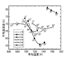
シミュレーションでは、熱分解反応を考慮することなく表2に示す条件のもとに、市販の熱流動解析プログラムを利用して、鋼管内部の流体に関する質量保存の式、運動量保存の式およびエネルギー保存の式を連立させ、3次元熱流動解析モデルにより鋼管内部の流動と伝熱挙動を評価し、管内の有効粘性係数、言い換えれば有効熱伝導度および有効拡散係数を計算した。なお、このとき、乱流の影響を考慮するため、乱流モデルを利用した。その結果を図2に示す。 In the simulation, using the commercially available thermal fluid analysis program under the conditions shown in Table 2 without considering the thermal decomposition reaction, the mass conservation equation, the momentum conservation equation and the energy conservation equation for the fluid inside the steel pipe are used. The equations were combined and the flow and heat transfer behavior inside the steel pipe were evaluated by a three-dimensional heat flow analysis model, and the effective viscosity coefficient in the pipe, in other words, the effective thermal conductivity and effective diffusion coefficient were calculated. At this time, a turbulent flow model was used in order to consider the influence of turbulent flow. The result is shown in FIG.
図2において、横軸は鋼管出口における流体の平均温度である。この平均温度が高いということは、鋼管外面から加えられた熱が効率よく伝熱していることを意味し、熱交換特性が優れていることを意味する。 In FIG. 2, the horizontal axis is the average temperature of the fluid at the steel pipe outlet. The high average temperature means that the heat applied from the outer surface of the steel pipe is efficiently transferred, and means that the heat exchange characteristics are excellent.
図2の縦軸は鋼管出口における流体の平均温度差である。この平均温度差が小さいということは、均一に温度が分布していることを意味する。言い換えれば、平均温度差の値が大きいというのは、鋼管の中心部は冷たく、内面近傍のみが局所的に加熱された状態にあることを意味し、熱分解反応特性が劣ることを意味する。 The vertical axis in FIG. 2 is the average temperature difference of the fluid at the steel pipe outlet. That this average temperature difference is small means that the temperature is uniformly distributed. In other words, the value of the average temperature difference being large means that the central portion of the steel pipe is cold and only the vicinity of the inner surface is in a locally heated state, and the thermal decomposition reaction characteristic is inferior.
図2の縦軸の値(平均温度差)は、管出口における平均温度をTmean(K)、同一断面上の任意の位置の温度をTlocal(K)とした場合に、下記の式により求められる値ΔTである。ただし、Sは管内の流体が通る空間の断面積である。 The value on the vertical axis (average temperature difference) in FIG. 2 is expressed by the following equation when the average temperature at the tube outlet is T mean (K) and the temperature at an arbitrary position on the same cross section is T local (K). The required value ΔT. However, S is a cross-sectional area of the space through which the fluid in the pipe passes.
図2から次の結論が得られる。
1)管の出口での流体の平均温度(図2の横軸)で表される熱交換特性は、管の内表面積が大きいほど大きい。そして、管の内表面積はリブの数が多いほど大きくなる。
2)管出口での流体の平均温度差(前記の(1)式で算出されるΔT)は、リブの傾斜角度が大きいほど小さい値になる。すなわち、熱分解反応特性は、リブの傾斜角度が大きいほど大きい。同じ傾斜角度であれば、リブ数が3条の場合に熱分解反応特性が最大となる。即ち、熱分解反応特性が大きい順にならべると、リブ数が3条の場合、4条の場合、2条の場合、5条の場合、1条の場合、8条の場合となる。
The following conclusion can be obtained from FIG.
1) The heat exchange characteristic represented by the average temperature of the fluid at the outlet of the pipe (horizontal axis in FIG. 2) is larger as the inner surface area of the pipe is larger. The inner surface area of the tube increases as the number of ribs increases.
2) The average temperature difference of the fluid at the pipe outlet (ΔT calculated by the above equation (1)) becomes smaller as the rib inclination angle is larger. That is, the thermal decomposition reaction characteristic increases as the rib inclination angle increases. If the inclination angle is the same, the thermal decomposition reaction characteristic becomes maximum when the number of ribs is three. That is, if the thermal decomposition reaction characteristics are arranged in descending order, the number of ribs is 3, the case of 4, the case of 2, the case of 5, the case of 1, the case of 1, and the case of
1−2.シミュレーション試験2
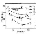
表3に示すように、リブの数を3条とし、リブの傾斜角度と高さを変えて、表2と同じ条件でシミュレーション試験を行い、リブ形状の影響について検討した。その結果を図3に示す。
1-2.
As shown in Table 3, the number of ribs was three, the inclination angle and height of the ribs were changed, a simulation test was performed under the same conditions as in Table 2, and the influence of the rib shape was examined. The result is shown in FIG.
図3から明らかなように、リブの高さが高いほど、横軸に示す平均温度が高くなる。即ち、熱交換特性が向上する。また、縦軸の平均温度差が小さくなり、熱分解反応特性も向上する。しかし、リブ高さが4.0mmでは熱分解反応特性が悪い。一方、リブ高さを10.0mmと高くしても、リブ高さが8.0mmや9.0mmの場合に較べて熱分解反応特性に著しい差は見られない。また、リブの傾斜角度が25°〜35°の範囲では効果に大きな差異はない。 As is apparent from FIG. 3, the average temperature shown on the horizontal axis increases as the height of the rib increases. That is, heat exchange characteristics are improved. In addition, the average temperature difference on the vertical axis is reduced, and the thermal decomposition reaction characteristics are also improved. However, when the rib height is 4.0 mm, the thermal decomposition reaction characteristic is poor. On the other hand, even if the rib height is increased to 10.0 mm, there is no significant difference in the thermal decomposition reaction characteristics compared to the rib height of 8.0 mm or 9.0 mm. Further, there is no significant difference in effect when the rib inclination angle is in the range of 25 ° to 35 °.
上記のようにリブの高さ(h)が高いほど熱交換特性および熱分解反応特性は向上する。しかし、リブが高すぎると、リブがガスの流れを拘束し、谷底部分の流体が滞留して熱分解反応特性が低下する。また、リブ山部の温度が低下して熱交換特性が低下する。そのうえ、コーキングが発生しやすくなる。さらには、熱間押出しや冷間圧延で高いリブを形成するのは困難である。一方、リブが低すぎると、管の内表面積が小さくなって熱交換特性が小さくなり、熱分解反応特性も低下する。 As described above, the higher the rib height (h), the better the heat exchange characteristics and thermal decomposition reaction characteristics. However, if the rib is too high, the rib restrains the gas flow, the fluid at the bottom of the valley stays, and the thermal decomposition reaction characteristics deteriorate. Moreover, the temperature of a rib crest part falls and a heat exchange characteristic falls. In addition, coking tends to occur. Furthermore, it is difficult to form high ribs by hot extrusion or cold rolling. On the other hand, if the rib is too low, the inner surface area of the tube is reduced, the heat exchange characteristics are reduced, and the thermal decomposition reaction characteristics are also lowered.
1−3.シミュレーション試験3
表4に示すように、リブ数を3条とし、リブ高さを5.5mmの一定にして、傾斜角度25°、30°および35°の各場合について谷底でのリブ幅wを変更して、表2と同じ条件でシミュレーション試験を行った。その結果を図4に示す。
1-3.
As shown in Table 4, the number of ribs was 3, and the rib height was fixed at 5.5 mm, and the rib width w at the valley bottom was changed for each of the inclination angles 25 °, 30 °, and 35 °, A simulation test was performed under the same conditions as in Table 2. The result is shown in FIG.
図4から明らかなとおり、h/wが小さいほど、すなわち山の形状がなだらかな波状となるほど、熱分解反応特性が低下する。すなわち、図2〜4の縦軸の平均温度差が大きくなる。一方、h/wが大きいほど熱分解反応特性は向上する。また、h/wが小さい場合、h/wが大きい尖った形状と比べて内表面積が小さくなるため、図2〜4の横軸の平均温度が低くなる。すなわち、熱交換特性が低下する傾向にある。 As is clear from FIG. 4, the smaller the h / w is, that is, the lower the shape of the mountain is, the more gently the wavy shape is, the lower the thermal decomposition reaction characteristics. That is, the average temperature difference on the vertical axis in FIGS. On the other hand, the larger the h / w, the better the thermal decomposition reaction characteristics. In addition, when h / w is small, the inner surface area is smaller than that of a sharp shape with a large h / w, so the average temperature on the horizontal axis in FIGS. That is, the heat exchange characteristics tend to decrease.
管の製造面では、h/wが大きすぎると、言い換えると、リブが薄く尖った形状になりすぎると、熱間押出しや冷間圧延では、高いリブを形成するのが難しくなる。 In terms of tube production, if h / w is too large, in other words, if the rib is too thin and sharp, it is difficult to form a high rib by hot extrusion or cold rolling.
1−4.シミュレーション試験に基づく最適リブ形状の決定
(1)リブ数
シミュレーション試験1の結果に基づいてリブ数は3条または4条とした。より好ましいリブ数は3条である。
(2)リブの傾斜角度
シミュレーション試験1の結果から、リブの傾斜角度は20°〜35°とした。より好ましいのは25°〜30°である。
(3)リブの形状(リブ高さh、谷底でのリブ幅w、リブの谷底内径Diの関係)
管の横断面でのリブ高さをh、谷底でのリブ幅をw、リブの谷底内径をDiとしたとき、h/Diを0.1〜0.2、リブ高さhと谷底でのリブ幅wとの比(h/w)を0.25〜1.0とした。
1-4. Determination of optimum rib shape based on simulation test
(1) Number of ribs Based on the results of
(2) Rib Inclination Angle From the results of
(3) Rib shape (relationship between rib height h, rib width w at the valley bottom, and valley bottom inner diameter Di of the rib)
When the rib height at the cross section of the pipe is h, the rib width at the valley bottom is w, and the inner diameter of the valley bottom of the rib is Di, h / Di is 0.1 to 0.2, and the rib height h is at the valley bottom. The ratio (h / w) to the rib width w was set to 0.25 to 1.0.
リブ高さhは、h/Diで規定することとした。即ち、熱分解反応用金属管には種々の寸法の管が使用されるが、管内面での流体の熱交換特性や熱分解反応特性を考慮した場合は、形状が相似形であると考えればよい。したがって、リブ高さhはh/Diで規定すればよいのである。シミュレーション試験2の結果では、図3に示すように、熱交換特性および熱分解反応特性ともに、リブ高さhが5.0mm以上で改善され、リブ高さが高いほど向上している。しかし、リブ高さが8.0〜10.0mmでは、高さが高いほど熱交換特性は向上するが熱分解反応特性に著しい差は見られない。一方、リブ高さは低い方がリブ成形加工しやすく管の製造が容易であるから好ましい。以上の理由により、好ましいリブ高さhを5.0〜10.0mmとし、シミュレーション試験2に用いた管の谷底内径Diは48mmであるため、h/Diの適正範囲を0.1〜0.2とした。また、リブ高さが高くなるほど冷間や熱間でのリブ成形加工が難しくなるため、シミュレーション試験での熱分解反応特性に差が無くなるリブ高さ8mm程度を上限とするのが好ましく、したがって、h/Diのより好ましい上限は0.17である。
The rib height h is defined by h / Di. In other words, pipes of various sizes are used as the metal tubes for the pyrolysis reaction, but if the heat exchange characteristics and pyrolysis reaction characteristics of the fluid on the inner surface of the pipe are taken into account, the shape is similar. Good. Therefore, the rib height h may be defined by h / Di. In the result of the
次にリブ高さhと谷底でのリブ幅wとの関係について述べる。
外部から加熱されたときの管の熱交換特性と熱分解反応特性(谷底流体と中心部の流体の行き来)、およびリブ形成の加工性を考えると、リブ形状は、リブ高さhのみで規定するのではなく、リブ高さhとリブの谷底でのリブ幅wとの比(h/w)でも規定する必要がある。シミュレーション試験3の結果から明らかなように、h/wが小さいほど平均温度差が大きく、熱分解反応特性は低下する。そのため、h/wの下限は0.25とした。一方、h/wが大きいほど熱分解反応特性は向上するので、h/wは大きいほど好ましい。したがって、h/wの好ましい下限は0.35であり、より好ましい下限は0.4である。
Next, the relationship between the rib height h and the rib width w at the valley bottom will be described.
Considering the heat exchange characteristics and pyrolysis reaction characteristics of the pipe when heated from the outside (going back and forth between the valley fluid and the center fluid) and the workability of rib formation, the rib shape is defined only by the rib height h Instead, it is also necessary to define the ratio (h / w) between the rib height h and the rib width w at the bottom of the rib. As is clear from the results of the
一方、シミュレーション試験3では、h/wの最大値を0.46までしか行っていないが、h/wが大きいほど熱分解反応特性(平均温度差)と熱交換特性(平均温度)が共に向上する傾向にある。また、リブ高さhを変更したシミュレーション試験2では、h/wを直線的には変更していないが、表3のリブ高さhと谷底の幅wの値からわかるように、h/wを0.28から0.84まで変更しており、図4に示すようにh/wが大きいほど熱分解反応特性(平均温度差)と熱交換特性(平均温度)が共に向上するため、上限を1.0とした。好ましい上限は0.7、より好ましい上限は0.55である。
On the other hand, in
2.本発明の金属管の製造方法
本発明の熱分解反応用金属管は、溶解、鋳造、熱間加工、冷間加工、溶接等の手段によって、継目無管、溶接管等の所要の管形状に成形して製造する。また、粉末冶金や遠心鋳造等の手法によって所要の管形状に成形してもよい。
2. Manufacturing method of metal pipe of the present invention The metal pipe for pyrolysis reaction of the present invention is formed into a required pipe shape such as a seamless pipe or a welded pipe by means of melting, casting, hot working, cold working, welding or the like. Molded and manufactured. Moreover, you may shape | mold into a required pipe shape by methods, such as powder metallurgy and centrifugal casting.
管の内面にらせん状のリブを形成する方法としては、下記の(a)〜(c)が例示される。
(a) 外周面に管の谷部に対応する山部と、管のリブに対応する谷部とが軸心線と平行な方向で形成されたマンドレルを備えた熱間押出製管プレス、または外周面に前記と同様の山部と谷部とが軸心線と平行な状態で形成されたマンドレルを備えた冷間圧延機により、リブ高さが管長手方向で同一の内面ストレートリブ付き管を製造する。次いで、この内面ストレートリブ付き管に捩り加工を加えて、内面らせん状リブ付き管とする。
(b) 外周面に管の谷部に対応する山部と、管のリブに対応する谷部とがらせん状に形成されたプラグを備える冷間引抜き製管機により、リブ高さが管長手方向で同一の内面らせん状リブ付き管とする。
(c) 管の内面にらせん状に肉盛溶接でリブを形成して、内面らせん状リブ付き管とする。
The following (a) to (c) are exemplified as a method of forming a helical rib on the inner surface of the tube.
(a) a hot-extrusion pipe press provided with a mandrel in which a crest corresponding to a trough of the pipe and a trough corresponding to a rib of the pipe are formed in a direction parallel to the axial center line on the outer peripheral surface, or An internally straight ribbed tube having the same rib height in the longitudinal direction of the tube by a cold rolling mill provided with a mandrel having a crest and a trough similar to the above on the outer peripheral surface in a state parallel to the axis. Manufacturing. Next, the inner straight ribbed tube is twisted to form an inner spiral ribbed tube.
(b) A cold drawn pipe making machine having a plug formed in a spiral shape with a crest corresponding to the trough of the pipe on the outer peripheral surface and a trough corresponding to the rib of the pipe, the rib height is The same inner spiral ribbed tube in the direction.
(c) A rib is formed on the inner surface of the pipe by overlay welding in a spiral manner to obtain a pipe with an inner spiral rib.
上記の方法の中でも、リブを熱間押出で管と一体成形した後、捩り加工でらせん状のリブを形成する製造方法では、粉末冶金や遠心鋳造で管を製造する場合や、管内面に肉盛溶接でリブを形成する場合と比べ、長尺品の製造が可能であり、10m以上の長い管が必要な場合でも管同士を溶接して長尺品とする必要がない。さらに、この方法で製造された管は、リブと母管との材質が同じであるから、異材を用いる肉盛溶接でリブを形成した管よりも高温強度や耐食性が優れており、炭化水素等の熱分解反応炉等の高温強度や耐食性、耐浸炭性が要求される用途に適している。 Among the above methods, in the manufacturing method in which the rib is integrally formed with the tube by hot extrusion, and then the spiral rib is formed by twisting, the tube is manufactured by powder metallurgy or centrifugal casting, Compared to the case where ribs are formed by prime welding, a long product can be manufactured, and even when a long tube of 10 m or longer is required, it is not necessary to weld the tubes to make a long product. Furthermore, the pipe manufactured by this method has the same material as the rib and mother pipe, and therefore has higher strength and corrosion resistance than pipes with ribs formed by overlay welding using different materials, such as hydrocarbons. It is suitable for applications that require high-temperature strength, corrosion resistance, and carburization resistance, such as pyrolysis reactors.
熱間押出でリブを形成する方法では、リブの高さが高すぎる場合には、リブがマンドレル形状に十分に沿わないで押し出されて、部分的に所定のリブ高さが確保できないことがある。したがって、熱間押出し法による製造では、成形できるリブの形状には制約があり、リブが過度に高すぎるのは好ましくない。 In the method of forming ribs by hot extrusion, when the height of the rib is too high, the rib may be extruded without sufficiently following the mandrel shape, and a predetermined rib height may not be partially secured. . Therefore, in the production by the hot extrusion method, the shape of the rib that can be formed is limited, and it is not preferable that the rib is too high.
3.本発明の金属管の材質
優れた耐浸炭性や耐コーキング性を強く要求される場合は、耐浸炭性や耐コーキング性に優れ、かつ高温強度や熱間加工性にも優れる下記の化学組成を有する管とするのが好ましい。なお、成分含有量に関する「%」は「質量%」を意味する。
3. The material of the metal pipe of the present invention When the excellent carburization resistance and caulking resistance are strongly required, the following chemical composition is excellent in carburization resistance and caulking resistance, and also in high temperature strength and hot workability. It is preferable to have a tube having. In addition, "%" regarding component content means "mass%".
(1) C:0.01〜0.6%、Si:0.01〜5%、Mn:0.1〜10%、P:0.08%以下、S:0.05%以下、Cr:15〜55%、Ni:20〜70%、N:0.001〜0.25%、残部がFeおよび不純物からなる化学組成を有する金属管。 (1) C: 0.01 to 0.6%, Si: 0.01 to 5%, Mn: 0.1 to 10%, P: 0.08% or less, S: 0.05% or less, Cr: 15 to 55%, Ni: 20 to 70%, N: A metal tube having a chemical composition of 0.001 to 0.25%, the balance being Fe and impurities.
(2) 上記の成分に加えて、さらに下記(i)ないし(vi)の少なくとも1群から選ばれた少なくとも1種の成分を含有する金属管。
(i) Cu:0.01〜5%、Co:0.01〜5%の1種または2種、
(ii) Mo:0.01〜3%、W:0.01〜6%、Ta:0.01〜6%の1種または2種以上、
(iii) Ti:0.01〜1%、Nb:0.01〜2%の1種または2種、
(iv) B:0.001〜0.1%、Zr:0.001〜0.1%、Hf:0.001〜0.5%の1種または2種以上、
(v) Mg:0.0005〜0.1%、Ca:0.0005〜0.1%、Al:0.001〜5%の1種または2種以上、
(vi) 希土類元素(REM):0.0005〜0.15%の1種または2種以上。
(2) A metal tube containing, in addition to the above components, at least one component selected from at least one group of the following (i) to (vi).
(i) Cu: 0.01 to 5%, Co: 0.01 to 5%, 1 type or 2 types,
(ii) Mo: 0.01 to 3%, W: 0.01 to 6%, Ta: 0.01 to 6%, one or more,
(iii) Ti: 0.01 to 1%, Nb: 0.01 to 2%, 1 type or 2 types,
(iv) One or more of B: 0.001 to 0.1%, Zr: 0.001 to 0.1%, Hf: 0.001 to 0.5%,
(v) One or more of Mg: 0.0005 to 0.1%, Ca: 0.0005 to 0.1%, Al: 0.001 to 5%,
(vi) Rare earth element (REM): One or more of 0.0005 to 0.15%.
以下に上記の各成分の作用効果と含有量の限定理由を述べる。 The effect of each component described above and the reason for limiting the content will be described below.
C:0.01〜0.6%
Cは、高温強度を確保するために0.01%以上の含有が有効である。一方、0.6%を超えると靱性が極端に悪くなるため、上限を0.6%とする。より好ましいのは0.02%〜0.45%、さらに好ましい範囲は0.02%〜0.3%である。
C: 0.01 to 0.6%
C is effective to contain 0.01% or more in order to ensure high temperature strength. On the other hand, if it exceeds 0.6%, the toughness is extremely deteriorated, so the upper limit is made 0.6%. A more preferable range is 0.02% to 0.45%, and a further preferable range is 0.02% to 0.3%.
Si:0.01〜5%
Siは、脱酸元素として必要であるが、さらに、耐酸化性や耐浸炭性の向上にも有効な元素である。この作用は、0.01%以上の含有量で発揮される。ただし、5%を超えると溶接性が劣化し、組織も不安定になるので、上限を5%とする。より好ましい範囲は0.1〜3%であり、もっとも好ましい範囲は0.3〜2%である。
Si: 0.01-5%
Si is necessary as a deoxidizing element, but is also an element effective for improving oxidation resistance and carburization resistance. This effect is exhibited at a content of 0.01% or more. However, if it exceeds 5%, the weldability deteriorates and the structure becomes unstable, so the upper limit is made 5%. A more preferable range is 0.1 to 3%, and a most preferable range is 0.3 to 2%.
Mn:0.1〜10%
Mnは、脱酸および加工性改善のために添加するものであり、このためにはその含有量を0.1%以上にする必要がある。またMnはオーステナイト生成元素であることからNiの一部をMnで置換することも可能であるが、過剰の含有では加工性が劣化することから、上限を10%とする。より好ましい範囲は0.1〜5%であり、もっとも好ましい範囲は0.1〜2%である。
Mn: 0.1-10%
Mn is added for deoxidation and processability improvement. For this purpose, its content needs to be 0.1% or more. Further, since Mn is an austenite-forming element, it is possible to substitute a part of Ni with Mn. However, if it is excessively contained, workability deteriorates, so the upper limit is made 10%. A more preferable range is 0.1 to 5%, and a most preferable range is 0.1 to 2%.
P:0.08%以下、S:0.05%以下
PおよびSは、結晶粒界に偏析し、熱間加工性を劣化させる。そのため、極力低減することが好ましいが、過剰な低減は製造コストの高騰を招くため、Pは0.08%以下、Sは0.05%以下とする。より好ましいのは、Pは0.05%以下、Sは0.03%以下であり、もっとも好ましいのは、Pは0.04%以下、Sは0.015%以下である。
P: 0.08% or less, S: 0.05% or less P and S are segregated at grain boundaries and deteriorate hot workability. Therefore, it is preferable to reduce as much as possible, but excessive reduction leads to an increase in manufacturing cost, so P is 0.08% or less and S is 0.05% or less. More preferably, P is 0.05% or less and S is 0.03% or less, and most preferably, P is 0.04% or less and S is 0.015% or less.
Cr:15〜55%
Crは、耐酸化性確保のための主要な元素であり、15%以上の含有が必要である。耐酸化性や耐浸炭性の点からCrの含有量は多い程好ましいが、過剰な添加は管の製造性や使用中の高温での組織安定性を低下させるので、含有量の上限を55%とする。加工性とともに組織安定性の劣化を防止するためには、上限を35%とすることが好ましい。より好ましい範囲は、20〜33%である。
Cr: 15-55%
Cr is a main element for ensuring oxidation resistance and needs to be contained in an amount of 15% or more. Higher Cr content is preferable from the standpoint of oxidation resistance and carburization resistance, but excessive addition reduces the manufacturability of the tube and the structural stability at high temperatures during use, so the upper limit of content is 55%. And In order to prevent deterioration of the structure stability as well as workability, the upper limit is preferably made 35%. A more preferable range is 20 to 33%.
Ni:20〜70%
Niは、安定したオーステナイト組織を得るために必要な元素であり、Cr含有量に応じて20〜70%の含有量が必要である。しかしながら、必要以上の含有は、コスト高と管の製造上の困難を招くので、より好ましい範囲は20〜60%であり、もっとも好ましい範囲は23〜50%である。
Ni: 20-70%
Ni is an element necessary for obtaining a stable austenite structure, and a content of 20 to 70% is required depending on the Cr content. However, excessive content causes high cost and difficulty in manufacturing the tube, so a more preferable range is 20 to 60%, and a most preferable range is 23 to 50%.
N:0.001〜0.25%
Nは、高温強度改善に有効な元素である。この効果を得るためには0.001%以上含有させることが必要である。一方、過剰な添加は加工性を大きく阻害するため、含有量の上限を0.25%とする。より好ましいNの含有量は0.001%〜0.2%である。
N: 0.001-0.25%
N is an element effective for improving the high-temperature strength. In order to obtain this effect, it is necessary to contain 0.001% or more. On the other hand, excessive addition significantly impairs processability, so the upper limit of the content is made 0.25%. A more preferable N content is 0.001% to 0.2%.
この他、所望により以下に示す元素の1種以上を含有させることもできる。
Cu:0.01〜5%、Co:0.01〜5%の1種または2種
CuおよびCoはオーステナイト相を安定にする他、高温強度向上に有効であり、それぞれ0.01%以上含有させてもよい。一方、それぞれの含有量が5%を超えると熱間加工性を著しく低下させる。したがって、それぞれ0.01〜5%とする。より好ましい範囲は、それぞれ0.01〜3%である。
In addition, one or more of the following elements may be contained as desired.
One or two of Cu: 0.01-5%, Co: 0.01-5%
Cu and Co are effective in improving the high temperature strength in addition to stabilizing the austenite phase, and each may be contained in an amount of 0.01% or more. On the other hand, when each content exceeds 5%, hot workability is remarkably lowered. Therefore, the content is set to 0.01 to 5%. More preferable ranges are 0.01 to 3%, respectively.
Mo:0.01〜3%、W:0.01〜6%、Ta:0.01〜6%の1種または2種以上
Mo、WおよびTaはいずれも固溶強化元素として高温強度向上に有効であり、その効果を発揮させるためには、それぞれの含有量を少なくとも0.01%以上とする必要がある。しかし、過剰の含有は加工性の劣化と組織安定性を阻害するので、Moは3%、WおよびTaはそれぞれ6%以下にする必要がある。Mo、W、Taのいずれも、より好ましいのは0.01〜2.5%、さらに好ましいのは0.01〜2%である。
One or more of Mo: 0.01 to 3%, W: 0.01 to 6%, Ta: 0.01 to 6%
Mo, W and Ta are all effective as a solid solution strengthening element for improving the high temperature strength. In order to exert the effect, the respective contents must be at least 0.01% or more. However, since excessive content inhibits deterioration of workability and structure stability, it is necessary to make
Ti:0.01〜1%、Nb:0.01〜2%の1種または2種
TiおよびNbは、極微量の添加でも高温強度および延性、靱性の改善に大きな効果があるが、それぞれ0.01%未満の含有量ではその効果が得られず、またTiでは1%を超えると、Nbは2%を超えると加工性や溶接性が低下する。
One or two of Ti: 0.01-1%, Nb: 0.01-2%
Ti and Nb have a great effect on improving high-temperature strength, ductility and toughness even when added in a very small amount, but when the content is less than 0.01%, the effect cannot be obtained. If it exceeds 2%, workability and weldability deteriorate.
B:0.001〜0.1%、Zr:0.00l〜0.1%、Hf:0.001〜0.5%の1種または2種以上
B、ZrおよびHfはいずれも粒界を強化し、熱間加工性および高温強度特性を改善するのに有効な元素であるが、いずれも0.001%未満の含有量ではその効果が得られない。一方、含有量が過剰になると溶接性を劣化させるので、それぞれ0.001〜0.1%、0.001〜0.1%、0.001〜0.5%とする。
One or more of B: 0.001 to 0.1%, Zr: 0.00l to 0.1%, Hf: 0.001 to 0.5% B, Zr and Hf both strengthen grain boundaries, hot workability and high temperature strength properties Although it is an element effective for improving the content, any effect is not obtained when the content is less than 0.001%. On the other hand, if the content is excessive, the weldability is deteriorated, so that the content is set to 0.001 to 0.1%, 0.001 to 0.1%, and 0.001 to 0.5%, respectively.
Mg:0.0005〜0.1%、Ca:0.0005〜0.1%、Al:0.001〜5%の1種または2種以上
Mg、CaおよびAlはいずれも熱間加工性を改善するのに有効な元素であり、その効果は、MgおよびCaは0.0005%以上、Alは0.001%以上の含有で得られる。Alはまた、浸炭性ガス環境に曝された場合に、CrとAlが主体の酸化スケールが生成するため金属管の耐浸炭性を著しく高めることができる。このためには、1.5%以上のAlを含有させることが有効である。一方、MgおよびCaの過剰な添加は溶接性を劣化させるため、含有量の上限をMgおよびCaでは0.1%とする。また、Alは5%を超えて含有されると、金属間化合物が合金中に析出するため靭性やクリープ延性が著しく低下する。
より好ましい含有量の範囲は、MgおよびCaでは0.0008〜0.05%、耐浸炭性を改善するために含有させる場合のAlでは2〜4%である。
One or more of Mg: 0.0005-0.1%, Ca: 0.0005-0.1%, Al: 0.001-5%
Mg, Ca and Al are all effective elements for improving hot workability, and the effect is obtained when Mg and Ca are contained in 0.0005% or more, and Al is contained in 0.001% or more. Al is also capable of significantly improving the carburization resistance of metal pipes when exposed to a carburizing gas environment because an oxide scale composed mainly of Cr and Al is produced. For this purpose, it is effective to contain 1.5% or more of Al. On the other hand, excessive addition of Mg and Ca deteriorates the weldability, so the upper limit of the content is 0.1% for Mg and Ca. On the other hand, if the Al content exceeds 5%, an intermetallic compound is precipitated in the alloy, so that toughness and creep ductility are significantly reduced.
A more preferable content range is 0.0008 to 0.05% for Mg and Ca, and 2 to 4% for Al when contained for improving carburization resistance.
希土類元素(REM):0.0005〜0.15%の1種または2種以上
希土類元素は、耐酸化性の向上に有効な元素であるが、いずれも0.0005%未満の含有量ではその効果が得られず、過剰な添加は加工性を低下させるので含有量の上限を0.15%とする。希土類元素とは、ランタノイドの15元素にYおよびScを合わせた17元素を意味し、その中では特にY、La、CeおよびNdのうちの1種以上を用いることが好ましい。
Rare earth element (REM): One or more of 0.0005 to 0.15% Rare earth element is an element effective in improving oxidation resistance, but any of the contents less than 0.0005% cannot obtain the effect. Excessive addition reduces workability, so the upper limit of the content is 0.15%. The rare earth element means 17 elements obtained by combining Y and Sc with 15 elements of lanthanoid, and among them, it is particularly preferable to use one or more of Y, La, Ce and Nd.
4.内面リブ付き管の製造例
表5に示す組成を有する中空ビレットを使用し、リブ形状に対応する凹凸を設けたマンドレルを用い、管内面に3条または4条のリブを有するストレートリブ付き管を熱間押出で製造した。この管に1150℃で軟化熱処理を施した後、管軸方向からの傾斜角が27°の捩り加工を行い、次いで1230℃で3分加熱した後に水冷する製品熱処理を施して、表6に記載の寸法のらせん状リブ付き管を得た。その管の横断面写真の複写図を図5として示す。図示のとおり、リブの山部の欠けや谷部の割れはまったく認められなかった。
4). Example of production of inner ribbed tube A straight ribbed tube having three or four ribs on the inner surface of the tube using a hollow billet having the composition shown in Table 5 and using a mandrel with irregularities corresponding to the rib shape. Manufactured by hot extrusion. The tube is subjected to a softening heat treatment at 1150 ° C., then twisted with an inclination angle of 27 ° from the tube axis direction, then heated to 1230 ° C. for 3 minutes, and then subjected to a product heat treatment that is water-cooled. A helically ribbed tube with dimensions of was obtained. A reproduction of a cross-sectional photograph of the tube is shown in FIG. As shown in the figure, no cracks in the ribs or cracks in the valleys were observed at all.
本発明の熱分解反応用金属管は、熱交換特性および熱分解反応特性が高いことから、少ないエネルギーで炭化水素等のオレフインの収率を高め得るだけでなく、耐コーキング性にも優れるので、製造装置自体の稼働率をも向上させることができ、エチレン等のオレフインの製造に限らず、あらゆる熱分解反応に用いる熱分解反応用金属管として利用できる。 Since the metal tube for pyrolysis reaction of the present invention has high heat exchange characteristics and pyrolysis reaction characteristics, not only can the yield of olefins such as hydrocarbons be increased with low energy, but also excellent coking resistance. The operating rate of the production apparatus itself can also be improved, and it can be used not only for the production of olefins such as ethylene, but also as a metal tube for thermal decomposition reaction used for all thermal decomposition reactions.
Claims (4)
h/Diが0.1〜0.2、h/wが0.25〜1.0であり、
上記のリブが熱間押出により管本体と一体に形成されたものであることを特徴とする熱分解反応用金属管。 In mass%, C: 0.01 to 0.6%, Si: 0.01 to 5%, Mn: 0.1 to 10%, P: 0.08% or less, S: 0.05% or less, Cr: 15 to 55%, Ni: 20 to 70% And N: 0.001 to 0.25 %, the remainder having a chemical composition composed of Fe and impurities, and extending in a spiral shape inclined at an angle of 20 to 35 ° with respect to the tube axis direction on the inner peripheral surface of the metal tube Or a metal tube for pyrolysis reaction in which four ribs are formed, and in the cross section of the rib, when the rib height is h, the rib width at the valley bottom is w, and the valley bottom inner diameter of the tube is Di ,
h / Di is 0.1 to 0.2, h / w is 0.25 to 1.0,
A metal tube for thermal decomposition reaction, wherein the rib is formed integrally with a tube body by hot extrusion.
(i) Cu:0.01〜5%、Co:0.01〜5%の1種または2種、 (i) Cu: 0.01 to 5%, Co: 0.01 to 5%, 1 type or 2 types,
(ii) Mo:0.01〜3%、W:0.01〜6%、Ta:0.01〜6%の1種または2種以上、 (ii) Mo: 0.01 to 3%, W: 0.01 to 6%, Ta: 0.01 to 6%, one or more,
(iii) Ti:0.01〜1%、Nb:0.01〜2%の1種または2種、 (iii) Ti: 0.01 to 1%, Nb: 0.01 to 2%, 1 type or 2 types,
(iv) B:0.001〜0.1%、Zr:0.001〜0.1%、Hf:0.001〜0.5%の1種または2種以上、 (iv) One or more of B: 0.001 to 0.1%, Zr: 0.001 to 0.1%, Hf: 0.001 to 0.5%,
(v) Mg:0.0005〜0.1%、Ca:0.0005〜0.1%、Al:0.001〜5%の1種または2種以上、 (v) One or more of Mg: 0.0005 to 0.1%, Ca: 0.0005 to 0.1%, Al: 0.001 to 5%,
(vi) 希土類元素(REM):0.0005〜0.15%の1種または2種以上。 (vi) Rare earth element (REM): One or more of 0.0005 to 0.15%.
Priority Applications (1)
| Application Number | Priority Date | Filing Date | Title |
|---|---|---|---|
| JP2011255020A JP2012107751A (en) | 2006-07-05 | 2011-11-22 | Metal tube for thermal decomposition reaction |
Applications Claiming Priority (3)
| Application Number | Priority Date | Filing Date | Title |
|---|---|---|---|
| JP2006185218 | 2006-07-05 | ||
| JP2006185218 | 2006-07-05 | ||
| JP2011255020A JP2012107751A (en) | 2006-07-05 | 2011-11-22 | Metal tube for thermal decomposition reaction |
Related Parent Applications (1)
| Application Number | Title | Priority Date | Filing Date |
|---|---|---|---|
| JP2008523706A Division JP5155163B2 (en) | 2006-07-05 | 2007-07-04 | Metal tube for pyrolysis reaction |
Publications (1)
| Publication Number | Publication Date |
|---|---|
| JP2012107751A true JP2012107751A (en) | 2012-06-07 |
Family
ID=38894541
Family Applications (2)
| Application Number | Title | Priority Date | Filing Date |
|---|---|---|---|
| JP2008523706A Active JP5155163B2 (en) | 2006-07-05 | 2007-07-04 | Metal tube for pyrolysis reaction |
| JP2011255020A Pending JP2012107751A (en) | 2006-07-05 | 2011-11-22 | Metal tube for thermal decomposition reaction |
Family Applications Before (1)
| Application Number | Title | Priority Date | Filing Date |
|---|---|---|---|
| JP2008523706A Active JP5155163B2 (en) | 2006-07-05 | 2007-07-04 | Metal tube for pyrolysis reaction |
Country Status (11)
| Country | Link |
|---|---|
| US (1) | US8114355B2 (en) |
| EP (1) | EP2037202B1 (en) |
| JP (2) | JP5155163B2 (en) |
| KR (2) | KR101153067B1 (en) |
| CN (1) | CN101484770B (en) |
| CA (1) | CA2655932C (en) |
| DK (1) | DK2037202T3 (en) |
| ES (1) | ES2693585T3 (en) |
| PL (1) | PL2037202T3 (en) |
| SG (1) | SG173347A1 (en) |
| WO (1) | WO2008004574A1 (en) |
Families Citing this family (16)
| Publication number | Priority date | Publication date | Assignee | Title |
|---|---|---|---|---|
| JP5289811B2 (en) * | 2008-03-31 | 2013-09-11 | 株式会社クボタ | Reaction tube |
| JP2011245513A (en) * | 2010-05-27 | 2011-12-08 | Sumitomo Metal Ind Ltd | Method for manufacturing pipe with inner surface fin |
| CN102399570B (en) * | 2010-09-16 | 2014-08-27 | 中国石油化工股份有限公司 | Method for restraining coking and carburization of radiant tube of ethylene cracking furnace, |
| EP2813286A1 (en) * | 2013-06-11 | 2014-12-17 | Evonik Industries AG | Reaction tube and method for the production of hydrogen cyanide |
| MX2016004436A (en) | 2013-10-11 | 2016-06-21 | Evonik Degussa Gmbh | Reaction tube and method for producing hydrogen cyanide. |
| CN105200338B (en) * | 2014-05-30 | 2017-07-28 | 中国石油化工股份有限公司 | A kind of anti-coking alloy material and application |
| WO2016099738A1 (en) * | 2014-12-16 | 2016-06-23 | Exxonmobil Research And Engineering Company | Alumina forming refinery process tubes with mixing element |
| CA2971073C (en) * | 2014-12-16 | 2019-04-09 | Exxonmobil Chemical Patents Inc. | Pyrolysis furnace tubes |
| EP3301075A1 (en) | 2016-09-28 | 2018-04-04 | Evonik Degussa GmbH | Method for producing hydrogen cyanide |
| CA3014861C (en) | 2016-11-09 | 2023-04-11 | Kubota Corporation | Alloy for overlay welding, powder for welding, and reaction tube |
| US11612967B2 (en) | 2016-11-09 | 2023-03-28 | Kubota Corporation | Alloy for overlay welding and reaction tube |
| CN108151570A (en) * | 2016-12-06 | 2018-06-12 | 中国石油化工股份有限公司 | A kind of manufacturing method of the augmentation of heat transfer pipe of heating furnace |
| CN107167019A (en) * | 2017-05-02 | 2017-09-15 | 青岛新力通工业有限责任公司 | Heat exchange elements and its manufacture method |
| CN109724444B (en) * | 2017-10-27 | 2020-12-18 | 中国石油化工股份有限公司 | Heat transfer pipe and cracking furnace |
| MY201675A (en) | 2017-10-27 | 2024-03-12 | China Petroleum & Chem Corp | Heat transfer enhancement pipe as well as cracking furnace and atmospheric and vacuum heating furnace including the same |
| JP6868146B1 (en) * | 2020-06-29 | 2021-05-12 | 株式会社クボタ | Pyrolysis tube with fluid agitation element |
Citations (5)
| Publication number | Priority date | Publication date | Assignee | Title |
|---|---|---|---|---|
| JPH06109392A (en) * | 1992-09-25 | 1994-04-19 | Kubota Corp | Manufacturing method of metal pipe with inner surface protrusion |
| JPH0882494A (en) * | 1994-07-11 | 1996-03-26 | Kubota Corp | Heat exchange tubes |
| JPH11201680A (en) * | 1998-01-12 | 1999-07-30 | Kobe Steel Ltd | Internally grooved tube |
| JP2005048284A (en) * | 2003-07-17 | 2005-02-24 | Sumitomo Metal Ind Ltd | Stainless steel and stainless steel pipe with carburization and caulking resistance |
| JP2005221153A (en) * | 2004-02-05 | 2005-08-18 | Sumitomo Metal Ind Ltd | Steel tube for pyrolysis reaction |
Family Cites Families (12)
| Publication number | Priority date | Publication date | Assignee | Title |
|---|---|---|---|---|
| JPS58173022A (en) | 1982-03-31 | 1983-10-11 | Sumitomo Metal Ind Ltd | Manufacture of tube having internal spiral rib |
| JPH01127896A (en) | 1987-11-13 | 1989-05-19 | Sumitomo Metal Ind Ltd | Pipe material for heat exchange |
| JPH09243283A (en) * | 1996-03-04 | 1997-09-19 | Kubota Corp | Metal tube for heat exchange with inner surface protrusion |
| JP3312839B2 (en) * | 1996-03-04 | 2002-08-12 | 株式会社クボタ | Method of manufacturing metal tube for heat exchange with inner projection |
| JP3284330B2 (en) * | 1996-03-12 | 2002-05-20 | 株式会社クボタ | Pyrolysis reaction tube for ethylene production with inner protrusion |
| JPH09263552A (en) * | 1996-03-29 | 1997-10-07 | Kubota Corp | Tube heating furnace |
| JP3416842B2 (en) * | 1998-01-07 | 2003-06-16 | 株式会社クボタ | Butt-welded heat exchange tube with internal projection |
| JP2001050679A (en) * | 1999-08-11 | 2001-02-23 | Hitachi Cable Ltd | Heat transfer tubes for heat exchange |
| US20050131263A1 (en) * | 2002-07-25 | 2005-06-16 | Schmidt + Clemens Gmbh + Co. Kg, | Process and finned tube for the thermal cracking of hydrocarbons |
| DE10233961A1 (en) | 2002-07-25 | 2004-02-12 | Schmidt + Clemens Gmbh + Co. Edelstahlwerk Kaiserau | Cracking hydrocarbon materials in presence of steam heated with pipes having helical inner ribs promoting uniform temperature in pipe wall |
| CN100342199C (en) * | 2002-11-15 | 2007-10-10 | 株式会社久保田 | Cracking tube with spiral fin |
| JP4114615B2 (en) * | 2004-02-03 | 2008-07-09 | 住友電気工業株式会社 | Signal injection extraction device |
-
2007
- 2007-07-04 DK DK07790434.0T patent/DK2037202T3/en active
- 2007-07-04 WO PCT/JP2007/063357 patent/WO2008004574A1/en not_active Ceased
- 2007-07-04 CN CN2007800249722A patent/CN101484770B/en active Active
- 2007-07-04 SG SG2011049046A patent/SG173347A1/en unknown
- 2007-07-04 EP EP07790434.0A patent/EP2037202B1/en active Active
- 2007-07-04 KR KR1020087030647A patent/KR101153067B1/en not_active Expired - Fee Related
- 2007-07-04 JP JP2008523706A patent/JP5155163B2/en active Active
- 2007-07-04 ES ES07790434.0T patent/ES2693585T3/en active Active
- 2007-07-04 KR KR1020117031344A patent/KR20120024872A/en not_active Withdrawn
- 2007-07-04 CA CA2655932A patent/CA2655932C/en not_active Expired - Fee Related
- 2007-07-04 PL PL07790434T patent/PL2037202T3/en unknown
-
2008
- 2008-12-30 US US12/318,477 patent/US8114355B2/en active Active
-
2011
- 2011-11-22 JP JP2011255020A patent/JP2012107751A/en active Pending
Patent Citations (5)
| Publication number | Priority date | Publication date | Assignee | Title |
|---|---|---|---|---|
| JPH06109392A (en) * | 1992-09-25 | 1994-04-19 | Kubota Corp | Manufacturing method of metal pipe with inner surface protrusion |
| JPH0882494A (en) * | 1994-07-11 | 1996-03-26 | Kubota Corp | Heat exchange tubes |
| JPH11201680A (en) * | 1998-01-12 | 1999-07-30 | Kobe Steel Ltd | Internally grooved tube |
| JP2005048284A (en) * | 2003-07-17 | 2005-02-24 | Sumitomo Metal Ind Ltd | Stainless steel and stainless steel pipe with carburization and caulking resistance |
| JP2005221153A (en) * | 2004-02-05 | 2005-08-18 | Sumitomo Metal Ind Ltd | Steel tube for pyrolysis reaction |
Also Published As
| Publication number | Publication date |
|---|---|
| US8114355B2 (en) | 2012-02-14 |
| EP2037202A1 (en) | 2009-03-18 |
| KR20090024160A (en) | 2009-03-06 |
| SG173347A1 (en) | 2011-08-29 |
| DK2037202T3 (en) | 2018-11-19 |
| KR20120024872A (en) | 2012-03-14 |
| CA2655932A1 (en) | 2008-01-10 |
| EP2037202B1 (en) | 2018-09-05 |
| WO2008004574A1 (en) | 2008-01-10 |
| US20090180935A1 (en) | 2009-07-16 |
| CN101484770A (en) | 2009-07-15 |
| EP2037202A4 (en) | 2013-11-06 |
| ES2693585T3 (en) | 2018-12-12 |
| CA2655932C (en) | 2011-10-25 |
| JP5155163B2 (en) | 2013-02-27 |
| KR101153067B1 (en) | 2012-06-04 |
| CN101484770B (en) | 2011-07-20 |
| JPWO2008004574A1 (en) | 2009-12-03 |
| PL2037202T3 (en) | 2019-03-29 |
Similar Documents
| Publication | Publication Date | Title |
|---|---|---|
| JP5155163B2 (en) | Metal tube for pyrolysis reaction | |
| EP0980729B1 (en) | Centrifugally cast tubes, method and apparatus of making same | |
| KR101411658B1 (en) | Thermal decomposition tube | |
| US10022699B2 (en) | Furnace coil fins | |
| EP3443053B1 (en) | Reactor for a cracking furnace | |
| US10207242B2 (en) | Alumina forming refinery process tubes with mixing element | |
| JP2010150553A (en) | Method for thermally decomposing hydrocarbon, and tube with rib | |
| EP1647794B1 (en) | External ribbed furnace tubes | |
| US12467698B2 (en) | Thermal cracking tube with fluid agitating element | |
| JPH09292191A (en) | Pyrolysis reaction tube for petrochemistry | |
| US8029749B2 (en) | Cracking furnace | |
| JP2001262159A (en) | Cracking coil | |
| JP2010138473A (en) | Method for producing metal tube | |
| US20140374213A1 (en) | Pinned furnace tubes | |
| Korkhaus | Failure mechanisms and material degradation processes at high temperatures in ammonia synthesis | |
| CN112745885A (en) | Heat-conducting furnace tube for two-pass radiation section ethylene cracking furnace and preparation method and application thereof | |
| CN113227328B (en) | Corrosion-resistant alloys for thermal cracking reactors | |
| JPH09217068A (en) | Pipe for thermally cracking hydrocarbon | |
| JP2006320909A (en) | Heat resistant multilayer metal tube | |
| JP2011245513A (en) | Method for manufacturing pipe with inner surface fin | |
| JPH11201681A (en) | Heat exchange tube | |
| JPH09264683A (en) | Pyrolysis reaction tube with fin for petrochemistry |
Legal Events
| Date | Code | Title | Description |
|---|---|---|---|
| A521 | Written amendment |
Free format text: JAPANESE INTERMEDIATE CODE: A523 Effective date: 20121011 |
|
| A711 | Notification of change in applicant |
Free format text: JAPANESE INTERMEDIATE CODE: A712 Effective date: 20121011 |
|
| A131 | Notification of reasons for refusal |
Free format text: JAPANESE INTERMEDIATE CODE: A131 Effective date: 20130423 |
|
| A02 | Decision of refusal |
Free format text: JAPANESE INTERMEDIATE CODE: A02 Effective date: 20130820 |