JP2012110164A - Rotor core for rotary electric machine - Google Patents
Rotor core for rotary electric machine Download PDFInfo
- Publication number
- JP2012110164A JP2012110164A JP2010258356A JP2010258356A JP2012110164A JP 2012110164 A JP2012110164 A JP 2012110164A JP 2010258356 A JP2010258356 A JP 2010258356A JP 2010258356 A JP2010258356 A JP 2010258356A JP 2012110164 A JP2012110164 A JP 2012110164A
- Authority
- JP
- Japan
- Prior art keywords
- caulking
- core plate
- core
- portions
- layer
- Prior art date
- Legal status (The legal status is an assumption and is not a legal conclusion. Google has not performed a legal analysis and makes no representation as to the accuracy of the status listed.)
- Pending
Links
Images




Landscapes
- Iron Core Of Rotating Electric Machines (AREA)
Abstract
Description
本発明は、複数のコアプレートを積層して形成する回転電機のロータコアに係り、詳しくは、そのかしめ構造に関する。 The present invention relates to a rotor core of a rotating electrical machine formed by laminating a plurality of core plates, and more particularly to a caulking structure thereof.
一般に、渦電流の発生を低減するために電磁鋼板を打ち抜いたコアプレートを積層して形成された回転電機のロータコアが知られている。従来、このような複数のコアプレート(鉄心用抜き板9)を積層したロータコア(回転子鉄心8)において、コアプレート9にポンチによって円形のかしめ部16を複数形成し、積層されたコアプレート同士をダボかしめによってかしめるものが案出されている(例えば、特許文献1参照)。 In general, a rotor core of a rotating electrical machine is known that is formed by laminating core plates made by punching electromagnetic steel sheets in order to reduce the generation of eddy currents. Conventionally, in a rotor core (rotor core 8) in which a plurality of such core plates (iron core blanks 9) are stacked, a plurality of circular caulking portions 16 are formed on the core plate 9 by punches, and the stacked core plates are Has been devised by caulking the dowel (see, for example, Patent Document 1).
ところで、上記特許文献1のようにコアプレートを積層してロータコアを形成するには、複数のコアプレートが必要となるが、コアプレートの形状が円環形状であると、母材からコアプレートを打ち抜く際に円環の中心部を使用できず、歩留まりが低くなる。そのため、このコアプレートを複数の円弧状のコアプレート片を連結して形成すると共に、コアプレート片の継ぎ目の位相(円周方向の位置)がずれるようにコアプレートを積層して(いわゆるレンガ積み)ロータコアを形成することがある(特許文献2参照)。
By the way, in order to form a rotor core by laminating core plates as in
そして、このようにコアプレート片をレンガ積みしてロータコアを形成すると共に、ダボかしめによってコアプレート同士をかしめると、歩留まりが高く、かつ単体でその形状を保持可能なロータコアを形成することができる。 Then, the core plate pieces are bricked in this way to form the rotor core, and when the core plates are caulked together by dowel caulking, a rotor core having a high yield and capable of holding the shape alone can be formed. .
しかしながら、上記コアプレートをコアプレート片を連結して形成すると、ロータコアが回転した際に遠心力に基づいて、かしめ部に対して、コアプレートの円周方向に向かって強い応力が発生する。 However, when the core plate is formed by connecting the core plate pieces, strong stress is generated in the circumferential direction of the core plate with respect to the caulking portion based on the centrifugal force when the rotor core rotates.
また、円形のかしめ部には、かしめられることによって、その全周に亘って引っ張りの残留応力が生じており、かしめ部の遠心力に基づいて応力が発生する部分には、これら引っ張りの残留応力と、遠心力に基づく応力との両方の応力が働いてしまう。 Further, the caulking portion of the circular shape causes tensile residual stress over the entire circumference, and the portion of the caulking portion where the stress is generated based on the centrifugal force causes the residual stress of the tensile force. Both stress and stress based on centrifugal force work.
そのため、ロータコアの回転強度を必要な強度に保つためには、コアプレートを分割せずにロータコアを形成する場合に比して、上記かしめ部の強度を向上させる必要がある。かしめ部の強度を向上させるには、上記遠心力に基づく応力及び残留応力の働く面積を大きくして、これらの応力を分散して受けることが考えられるが、円形のかしめ部の直径を大きくするとロータコアの径方向の幅を大きくする必要があり、ロータコアが大径化する虞があると共に、歩留まりも悪化してしまうという問題があった。 Therefore, in order to keep the rotational strength of the rotor core at a required strength, it is necessary to improve the strength of the caulking portion as compared with the case where the rotor core is formed without dividing the core plate. In order to improve the strength of the caulking portion, it is conceivable to increase the area where the stress based on the centrifugal force and the residual stress work and to receive these stresses in a distributed manner. However, when the diameter of the circular caulking portion is increased. There is a problem in that it is necessary to increase the radial width of the rotor core, the rotor core may be increased in diameter, and the yield is also deteriorated.
一方、ロータコアを厚くして、遠心力に基づく応力及び残留応力が働く面積を大きくしようとした場合、ロータコアに発生する渦電流が大きくなり、回転電機の効率が低下するという問題があった。 On the other hand, when the rotor core is made thick to increase the area where the stress and residual stress based on the centrifugal force are applied, the eddy current generated in the rotor core is increased, and the efficiency of the rotating electrical machine is reduced.
更に、上記遠心力に基づいて発生する応力は、コアプレートの円周方向に複数形成されたかしめ部の内、その円周方向の位置によって働く応力の大きさにばらつきがあり、特定のかしめ部に大きな応力が生じてしまうという問題があった。 Furthermore, the stress generated based on the centrifugal force varies among the caulking portions formed in the circumferential direction of the core plate, depending on the circumferential position, and the specific caulking portion. There has been a problem that a large stress is generated.
そこで、本発明は、かしめ部を、遠心力に基づく応力を受ける部分と、残留応力が生じる部分とが分離するように形成すると共に、各かしめ部に働く応力を出来る限り均一にすることによって、上記課題を解決したロータコアを提供することを目的とする。 Therefore, in the present invention, the caulking part is formed so that the part receiving the stress based on the centrifugal force and the part where the residual stress is generated are separated, and by making the stress acting on each caulking part as uniform as possible, It aims at providing the rotor core which solved the above-mentioned subject.
本発明は、円環状のコアプレート(2)を複数積層して形成されると共に、前記コアプレート(2)を均等に分割した円弧状のコアプレート片(3)が連結されて前記コアプレート(2)の一層が形成され、かつ前記コアプレートの前記コアプレート片(3)の継ぎ目(D1,D2)の円周方向(C)の位置が、一層毎に交互に異なるように構成された回転電機のロータコア(1)において、
前記コアプレート片(3)は、積層方向一方側の面に形成された凸部(11)と、積層方向他方側で前記凸部(11)と同じ位置に形成され、前記コアプレート片(3)が積層された際に積層方向他方側の面と接する他層の前記コアプレート片(3)の凸部(11)と嵌合する凹部(12)と、を有するかしめ部(10)を、前記コアプレート(2)の円周方向に複数備え、
前記複数のかしめ部(101〜108)を、前記他層のコアプレート片(3)の継ぎ目位置(D2)に隣接する第1かしめ部(104,105)と、前記コアプレート片(3)の端部に設けられた第2かしめ部(101,108)と、これら第1及び第2かしめ部の間に形成される第3かしめ部(102,103,106,107)とから構成すると共に、前記第1かしめ部(104,105)の凹部(124,125)が、前記他層の前記コアプレート片(3)の前記第2かしめ部(101,108)の凸部(111,118)に嵌合し、前記第2かしめ部(101,108)の凹部(121,128)が、前記他層のコアプレート片(3)の前記第1かしめ部(104,105)の凸部(114,115)に嵌合し、前記第3かしめ部(102,103,106,107)の凹部(122,123,126,127)が、前記他層の前記コアプレート片(3)の前記第3かしめ部(102,103,106,107)の凸部(112,113,116,117)に嵌合するように前記コアプレート(2)を積層し、
これら第1乃至第3のかしめ部(101〜108)の凸部(111〜118)及び凹部(121〜128)の嵌め合いを、前記コアプレート(2)の半径方向(R)では締り嵌めとすると共に、前記コアプレート(2)の円周方向(C)では所定の隙間(d2)を存する隙間嵌めとしかつ、前記第2かしめ部(101,108)の凹部(121,128)と前記他層のコアプレート片(3)の前記第1かしめ部(104,105)の凸部(114,115)との間の円周方向(C)の前記隙間(d21)を、前記第3かしめ部(102,103,106,107)の凹部(122,123,126,127)と前記他層のコアプレート片(3)の前記第3かしめ部(102,103,106,107)の凸部(112,113,116,117)との間の円周方向(C)の前記隙間(d23,d24)よりも大きくした、
ことを特徴とする。
The present invention is formed by laminating a plurality of annular core plates (2), and arc-shaped core plate pieces (3) obtained by equally dividing the core plate (2) are connected to form the core plate ( 2), and the positions of the circumferential direction (C) of the seams (D 1 , D 2 ) of the core plate pieces (3) of the core plate are alternately different for each layer. In the rotor core (1) of the rotating electrical machine
The core plate piece (3) is formed at the same position as the convex portion (11) on the surface on one side in the stacking direction and the convex portion (11) on the other side in the stacking direction. A caulking portion (10) having a concave portion (12) fitted to the convex portion (11) of the core plate piece (3) of the other layer that is in contact with the surface on the other side in the laminating direction when the A plurality of core plates (2) are provided in the circumferential direction,
The plurality of caulking portions (10 1 to 10 8 ), the first caulking portion (10 4 , 10 5 ) adjacent to the joint position (D 2 ) of the core plate piece (3) of the other layer, and the core plate A second caulking portion (10 1 , 10 8 ) provided at an end of the piece (3) and a third caulking portion (10 2 , 10 3 , 10) formed between the first and second caulking portions. 6 , 10 7 ), and the concave portions (12 4 , 12 5 ) of the first caulking portions (10 4 , 10 5 ) are the second caulking portions of the core plate piece (3) of the other layer.
The fitting of the convex portions (11 1 to 11 8 ) and the concave portions (12 1 to 12 8 ) of the first to third caulking portions (10 1 to 10 8 ) is determined in the radial direction of the core plate (2) ( R) is an interference fit, and a gap fit with a predetermined gap (d 2 ) is provided in the circumferential direction (C) of the core plate (2) and the second caulking portion (10 1 , 10 8 ). Circumferential direction between the concave portions (12 1 , 12 8 ) and the convex portions (11 4 , 11 5 ) of the first caulked portions (10 4 , 10 5 ) of the core plate piece (3) of the other layer ( the clearance of C) a (d 21), said third crimping
It is characterized by that.
また、前記第1かしめ部(104,105)の凹部(124,125)と前記他層のコアプレート片(3)の前記第2かしめ部(101,108)の凸部(111,118)との間の円周方向(C)の隙間(d22)の大きさを、前記第2かしめ部(101,108)の凹部(121,128)と前記他層のコアプレート片(3)の前記第1かしめ部(104,105)の凸部(114,115)との間の円周方向(C)の前記隙間(d21)以下でかつ、前記第3かしめ部(102,103,106,107)の凹部(122,123,126,127)と前記他層のコアプレート片(3)の前記第3かしめ部(102,103,106,107)の凸部(112,113,116,117)との間の円周方向(C)の前記隙間(d23,d24)以上となるように設定すると好適である。 Further, the concave portion (12 4 , 12 5 ) of the first caulking portion (10 4 , 10 5 ) and the convex portion of the second caulking portion (10 1 , 10 8 ) of the core plate piece (3) of the other layer. The size of the gap (d 22 ) in the circumferential direction (C) between (11 1 , 11 8 ) and the recess (12 1 , 12 8 ) of the second caulking portion (10 1 , 10 8 ) The clearance (d 21 ) in the circumferential direction (C) between the convex portion (11 4 , 11 5 ) of the first caulking portion (10 4 , 10 5 ) of the core plate piece (3) of the other layer. or less and, said third crimping portions recesses (10 2, 10 3, 10 6, 10 7) (12 2, 12 3, 12 6, 12 7) and the core plate piece of the other layer (3) Convex parts (11 2 , 11 3 , 11 6 , 11 7 ) of the third caulking part (10 2 , 10 3 , 10 6 , 10 7 ) It is preferable to set it so as to be equal to or larger than the gap (d 23 , d 24 ) in the circumferential direction (C).
なお、上記カッコ内の符号は、図面と対照するためのものであるが、これにより各請求項の構成に何等影響を及ぼすものではない。 In addition, although the code | symbol in the said parenthesis is for contrast with drawing, it has no influence on the structure of each claim by this.
請求項1に係る発明によると、かしめ部の嵌め合いを、コアプレートの半径方向は締り嵌めとすると共に、コアプレートの円周方向は所定の隙間を有する隙間嵌めとすることによって、遠心力に基づく応力を受けるかしめの円周方向部分に、かしめ部をかしめる際に生じる引っ張り残留応力が生じることを防止することが出来る。また、上記隙間を、ロータコアの回転時には、嵌合するかしめ部の凸部と凹部とが当接するような隙間としたことによって、遠心力に基づく応力をかしめ部の残留応力が生じていない部分で受けることができる。更に、1つのコアプレート片に複数のかしめ部を設け、これら複数のかしめ部のうち、同じ層のコアプレートの継ぎ目位置に隣接するかしめ部の凹部が、他層のかしめ部の凸部と嵌合して形成する上記隙間を、それ以外のかしめ部の凹部が、他層のかしめ部の凸部と嵌合して形成する隙間よりも大きくすることによって、かしめ部の円周方向の位置に依らず、1つのコアプレート片の各かしめ部に掛る応力の差を、出来る限り少なくすることができる。そして、これら残留応力が生じる部分と、遠心力を受ける部分とを分離するようにかしめ部を形成したことと、かしめ部の隙間を調整して、1つのコアプレート片に形成される複数のかしめ部に均等に応力が生じるようにしたこととが相俟って、回転強度の高いロータコアを形成することができる。 According to the first aspect of the present invention, the fitting of the caulking portion is made into an interference fit in the radial direction of the core plate, and the circumferential direction of the core plate is set as a clearance fit having a predetermined gap, so that centrifugal force can be applied. It is possible to prevent a tensile residual stress generated when caulking is caulked in the circumferential direction portion of caulking subjected to stress based on the stress. Further, when the rotor core is rotated, the gap is such that the convex portion and the concave portion of the caulking portion to be fitted come into contact with each other, so that stress based on centrifugal force is not generated in the portion where the residual stress of the caulking portion is generated. Can receive. In addition, a plurality of caulking portions are provided on one core plate piece, and among these caulking portions, the concave portion of the caulking portion adjacent to the seam position of the core plate of the same layer is fitted with the convex portion of the caulking portion of the other layer. The above-mentioned gap formed together is made larger than the gap formed by fitting the concave portion of the other caulking portion with the convex portion of the caulking portion of the other layer, so that the caulking portion is positioned in the circumferential direction. Regardless, the difference in stress applied to each caulking portion of one core plate piece can be reduced as much as possible. The caulking portion is formed so as to separate the portion where the residual stress is generated from the portion receiving the centrifugal force, and a plurality of caulking formed on one core plate piece is adjusted by adjusting a gap between the caulking portions. Combined with the fact that the stress is uniformly generated in the part, it is possible to form a rotor core with high rotational strength.
請求項2に係る発明によると、第1かしめ部の凹部と他層のコアプレート片の第2かしめ部の凸部との間の上記隙間の大きさを、第2かしめ部の凹部と他層のコアプレート片の第1かしめ部の凸部との間の隙間以下でかつ、第3かしめ部の凹部と他層のコアプレート片の第3かしめ部の凸部との間の円周方向の隙間以上となるように設定することによって、1つのコアプレート片に形成される複数のかしめ部により均等に応力を生させることができる。 According to the invention which concerns on Claim 2, the magnitude | size of the said clearance gap between the recessed part of a 1st crimping part and the convex part of the 2nd crimping part of the core plate piece of another layer is made into the recessed part and other layer of a 2nd crimping part. Or less than the gap between the first caulking portion of the core plate piece and the concave portion of the third caulking portion and the convex portion of the third caulking portion of the core plate piece of the other layer. By setting so that it may become more than a clearance gap, a stress can be equally produced by the several crimping part formed in one core plate piece.
以下、本発明の実施形態に係る回転電機のロータコアについて、図面に基づいて説明をする。なお、以下の説明中において、締り嵌めとは、嵌め合わす凸部の幅を凹部の幅よりも少し大きくした形式の嵌め合いのことを言い、隙間嵌めとは、凸部と凹部との間に所定の隙間を有した形式の嵌め合いのことを言う。 Hereinafter, a rotor core of a rotating electrical machine according to an embodiment of the present invention will be described with reference to the drawings. In the following description, an interference fit refers to a fit of a type in which the width of the convex portion to be fitted is slightly larger than the width of the concave portion, and the gap fit is a gap between the convex portion and the concave portion. This means a type of fit with a predetermined gap.
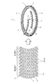
図1及び図2に示すように、IPMモータ(回転電機)用のロータコア1は、円環状のコアプレート2が複数積層されて形成されている。該コアプレート2は、電磁鋼板の母材から打ち抜かれた板状の部材であり、歩留まりの向上を図るために、該コアプレート2を均等に分割(本実施形態では5分割)した円弧状のコアプレート片3を連結して形成されている。
As shown in FIGS. 1 and 2, a
具体的には、このコアプレート片3の一端部には、円周方向に隣接するコアプレート片3と連結するための突起部5aが形成されていると共に、他端部には、上記コアプレート片3の突起部5aが嵌め込まれる嵌め込み部5bが形成されている。1つのコアプレート2には、これらコアプレート片同士の継ぎ目D1,D2、即ち突起部5aと嵌め込み部5bとの接合箇所がコアプレート片3の数と同数だけ形成されている。
Specifically, one end portion of the
上記コアプレート2は、どの一層のコアプレート2も同じ形状のコアプレート片3を結合して円環状に形成されているが、積層方向に重なる(隣接する)コアプレート2に対してコアプレート片3の継ぎ目D1,D2の円周方向の位置(位相)を一層毎に交互にずらすレンガ積みによって積層されている。即ち、コアプレート2の継ぎ目D1,D2の円周方向の位置が、積層方向に重なる前記コアプレート同士で交互に異なるように構成されている。例えば図1において、便宜的にロータコア1の底部から数えて積層されたコアプレート2を奇数層と、偶数層とに分けると、偶数層のコアプレート片3Eは、その端部位置(継ぎ目D1)が奇数層のコアプレート片3Oの端部位置(継ぎ目D2)に対して位置が所定角度ずれるように配設されている。
The core plate 2 is formed in an annular shape by connecting the
また、上記コアプレート片3には、ネオジウム磁石などの希土類永久磁石が嵌挿される磁石嵌挿穴6と、積層された複数のコアプレート2同士を締結するかしめ部10と、がその円周方向に複数、形成されている。このかしめ部10は、磁石嵌挿穴6の両端部の内周側にそれぞれ設けられており、コアプレート2が仮組された後にかしめ部10をかしめることによって、ロータコア1は、各コアプレート2がばらばらにならずに、その形状を保持できるようになっている。
The
ついで、上記かしめ部10について詳しく説明をする。図2及び図3に示すように、かしめ部10は、プレス成型によってコアプレート片を一方の面(積層方向一方側の面)側に突出させた凸部(ダボ)11と、この凸部11が形成されることにより、コアプレート片3の凸部11の裏面(積層方向他方側で凸部11と同じ位置)に形成される凹部12と、から構成されており、この凹部12に他のコアプレート片3の凸部11が嵌合することによって、ダボかしめされるようになっている。
Next, the
ところで、これら凸部11及び凹部12からなるかしめ部10には、かしめられる際に発生する残留応力と、ロータコア1が回転する際に掛る遠心力に基づく応力と、の2つの応力が作用する。
By the way, two stresses, a residual stress generated when caulking and a stress based on a centrifugal force applied when the
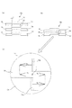
上記残留応力は、かしめ部10が締り嵌めされることによって生じる応力であり、図4に示す互いに積層されるA〜C層LA,LB,LCのコアプレート片3A,3B,3Cを例に取って説明すると、かしめ部10は、締り嵌めとなる部分10aにおいて、凸部11の幅Wr1が締め代d1分だけ凹部12の幅Wr2よりも大きくなるように形成されている(図4(a)参照)。
The residual stress is a stress caused by the
図4(b)に示すように、コアプレート片3A,3B,3Cは、凸部11が締め代分d1だけ幅狭な凹部12に圧入されて締り嵌めされることによって、その積層方向に連結されるが、図4(c)のコアプレート片3Bのように、凸部11が他の層(C層LC)のコアプレート片3Cの凹部12に圧入されると、圧入された凸部11は、C層LCの凹部12の壁部12aから圧縮する方向(C層LCの凹部からB層LBの凸部11に向かう方向)の応力Tcを受ける。
As shown in FIG. 4B, the
一方、凹部12に他の層(A層LA)の凸部が圧入されると、その凹部12には、A層LAの凸部11の壁部11aから拡大する方向(A層LAの凸部11からB層LBの凹部12向かう方向)に応力Ttが作用する。そして、これら凸部11及び凹部12を接続するB層LBの接続部Iでは、互いに反対方向に向かって働く上記応力Tc,Ttが掛り、これら凸部側及び凹部側からの応力Tc,Ttが釣り合って、上述した引っ張りの残留応力が発生する。
On the other hand, when the convex portion of the other layers in the recess 12 (A layer L A) is pressed, the the
また、上記遠心力に基づく応力は、ロータコア1が回転することによってかしめ部10に発生する応力であり、ロータコア1が回転すると、図5(a)に示すように、重なり合うコアプレート片3E,3Oのそれぞれには遠心力FE,FOが作用する。
Further, the stress based on the centrifugal force is a stress generated in the
これら重なり合うコアプレート片3E,3Oに作用する遠心力FE,FOを、コアプレート片3E,3Oの円周方向成分FEX,FOXと半径方向成分FEY,FOYとに分けて考えると、図5(b)に示すように、半径方向成分FEY,FOYは、どちらもコアプレート2の中心から外径側に向かう方向に作用するため、重なり合うコアプレート片3E,3O間で互いに反力を受けることができず、層の異なるコアプレート片3E,3O同士を連結するかしめ部10には、ほとんど力が作用しない。
Centrifugal forces F E and F O acting on these overlapping
一方、遠心力FE,FOの円周方向成分FOX,FEXは、重なり合うコアプレート片3E,3O間でその作用方向が異なるため、これらコアプレート片3E,3Oを連結するかしめ部10で互いに反力を受けることができる。即ち、コアプレート片3Eの端部に形成されたかしめ部108に着目すると、重なり合うコアプレートが円周方向に沿って反対側に移動しようとすることによって、かしめ部108には、コアプレート2の円周方向に遠心力に基づく応力が発生する。なお、遠心力FE,FOの半径方向成分FEY,FOYは、その力をコアプレート2全体のかしめ部で分散して受けるが、特にコアプレート片3の継ぎ目D1,D2近くのかしめ部に大きな力が作用する。
On the other hand, the circumferential direction components F OX , F EX of the centrifugal forces F E , F O have different directions of action between the overlapping
上述した図3に示す本発明に係るかしめ部10は、これら遠心力に基づく応力と、引っ張りの残留応力とが同じ場所に生じないように構成されており、上記残留応力が生じる締り嵌めとなる部分10aと、遠心力による応力が生じる部分10bと、が別々に分かれて構成されている。
The
具体的には、かしめ部10は、凸部11及び凹部12のコアプレート2の円周方向(コアプレート片3の接線方向)Cの壁部11a,12aを直線状に形成した直線部10aと、これら凸部11及び凹部12のコアプレート2の半径方向Rの壁部11b,12bを所定の曲率の円弧状に形成した円弧部10bと、を有し、上記直線部10a間を円弧部10bによって結んだ長円形状をしており、この直線部10aによってかしめ部10の締り嵌めとなる部分を形成している。
Specifically, the
即ち、かしめ部10は、直線形状の壁部11a,11a間の幅である凸部11のコアプレート2の半径方向Rの幅Wr2を、直線状の壁部12a,12a間の幅である凹部12のコアプレート2の半径方向Rの幅Wr1よりも大きくし(Wr2>Wr1)、これら凸部11及び凹部12の半径方向Rの嵌め合いを締り嵌めとしている。
That is, the
また、かしめ部10には、その円周方向に遠心力FE,FOに基づく応力が作用するため、凸部11及び凹部12の円周方向の端部である上記円弧部10bは、円弧形状の壁部11b,12b間に所定の隙間d2を有する隙間嵌めとなっている。即ち、この円弧部10bによりかしめ部10の隙間嵌めとなる部分を形成しており、円弧状の壁部11b,11b間の幅に相当する凸部11のコアプレート2の円周方向Cの幅Wc2が、円弧状の壁部12b,12b間の幅に相当する凹部12のコアプレート2の円周方向の幅Wc1よりも小さくなっている(Wc1>Wc2)。
In addition, since the
なお、上記円弧部10bでは、かしめ部10がかしめられた時点では、凸部11の円弧状の壁部11bと、凹部12の円弧状の壁部12bとの間に隙間d2が存在しているため、これら壁部11b,12b間で遠心力FE,FOの円周方向成分FOX,FEXの反力を受けることができないが、この隙間d2は、ロータコア1が回転して重なり合うコアプレート片3E,3Oが円周方向に離れるように移動しようとすると、これらコアプレート片間の微小なズレや、コアプレート片3E,3Oの弾性変形により無くなって、凸部11の円弧状の壁部11bと凹部12の円弧状の壁部12bとが当接できるように形成されている。言い換えると、ロータコア1の回転時にはこれら凸部11と凹部12とが当接するような隙間d2となっている。
In the
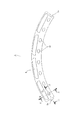
ついで、上述したかしめ部10のコアプレート片3の円周方向の位置による違いについて説明をする。図6に示すように、1つのコアプレート片3には、その円周方向に複数(本実施形態では8つ)のかしめ部101〜108が形成されており、これらかしめ部101〜108は、積層方向に重なる前記コアプレート2の継ぎ目D2位置(継ぎ目の円周方向位置)に隣接する第1かしめ部104,105と、コアプレート片3Eの端部に設けられた第2かしめ部101,108と、これら第1及び第2かしめ部の間に形成される第3かしめ部102,103,106,107とから構成されている。
Next, the difference depending on the position of the
図6(b),(c)に示すように、ロータコア1は、上記第1かしめ部104,105の凸部114,115及び凹部124,125が、凸部側及び凹部側の他層の前記コアプレート片3Oの第2かしめ部101,108の凹部121,128及び凸部111,118にそれぞれ嵌合し、第3かしめ部102,103,106,107の凸部112,113,116,117及び凹部122,123,126,127が、凸部側及び凹部側の他層の前記コアプレート片3Oの第3かしめ部102,103,106,107の凹部122,123,126,127及び凸部112,113,116,117にそれぞれ嵌合するようにコアプレート2が積層されている。
As shown in FIGS. 6B and 6C, the
これら第1乃至第3のかしめ部101〜108の凸部111〜118及び凹部121〜128の嵌め合いは、上述したように、コアプレート2の半径方向Rでは締り嵌めとなっていると共に、前記コアプレート2の円周方向Cでは、ロータコア1の回転時にこれら凸部111〜118と凹部121〜128とが当接するような隙間d2を存する隙間嵌めとなっており、この隙間d2は、ひとつのかしめ部10に対して、凸部11と上層(凸部側の層)のコアプレート片3O1のかしめ部10の凹部12との間(例えば、かしめ部104に対しては凸部側隙間d21)と、凹部12と下層(凹部部側の層)のコアプレート片3O2のかしめ部10の凸部11との間(例えば、かしめ部104に対しては凹部側隙間d22)と、に形成される。
It fits of the first to the
ところで、図8のグラフS1は、上記隙間d2を上記第1乃至第3かしめ部101〜108間で同一とした場合に、各かしめ部101〜108の凸部111〜118に掛る応力の大きさを表したものであるが、これら第1乃至第3かしめ部101〜108間で隙間d2を同一とすると、コアプレート2の継ぎ目D1,D2に隣接する第1及び第2かしめ部101,104,105,108の凸部111,114,115,118、特に積層方向に重なるコアプレート2の継ぎ目D2位置に隣接する第1かしめ部104,105の凸部114,115に大きな応力が作用することが分かる。
Incidentally, the graph S 1 in FIG. 8, when the gap d 2 were the same among the first to third crimping
これは、ロータコア1が回転すると、コアプレート片3の端部は中央部に比して遠心力による影響を大きく受けるためであり、コアプレート2の継ぎ目D1,D2に隣接した第1及び第2かしめ部101,104,105,108に働く応力は、第3かしめ部102,103,106,107に働く応力よりも大きくなる。
This is because when the
とりわけ、第1かしめ部104,105は、これら隣接する一対の第1かしめ部104,105間に上下層の分割位置(継ぎ目D1)が位置するため、それぞれ別のコアプレート片3o1、3o2のかしめ部101,108と嵌合している。そして、ロータコア1が回転して遠心力が発生すると、上下層のコアプレート片3o1,3o2は、円周方向Cに隣接するコアプレート片同士が継ぎ目D1を境にして離れる方向に移動しようとするが、これら別々の離れる方向に移動するコアプレート片3o1,3o1、3o2,3o2と嵌合する第1かしめ部104,105は、上下層のコアプレート片3o1,3o2の移動によって、同一コアプレート片3E内において円周方向Cに離れる方向に引っ張られるため、大きな引っ張り応力が働く。
In particular, since the
一方、継ぎ目D1に隣接するかしめ部101,108の凸部111,118では、上述したように継ぎ目D1で別々のコアプレート片3o,3oに分かれているため、分割されたコアプレート片3o,3o間で直接的に力が作用することがないと共に、継ぎ目D1に力を逃がすことができるため、継ぎ目D2に隣接するかしめ部104,105の凸部114,115ほど大きな応力は生じない。
On the other hand, the
本実施形態では、図6及び図7に示すように、上記第1及び第2かしめ部101,104,105,108に高い応力が発生しないように、第1かしめ部104,105と他層の前記コアプレート片3O1,3O2の第2かしめ部101,108との間の隙間d21,d22を、第3かしめ部102,103,106,107と他層のコアプレート片3O1,3O2の第3かしめ部102,103,106,107との間の前記隙間d23,d24よりも大きく形成している。
In the present embodiment, as shown in FIGS. 6 and 7, the first and
特に凸部114,115に高い引っ張りの応力が発生しやすい第1かしめ部104,105に掛る応力を低減するために、第1乃至第3かしめ部101〜108は、第1かしめ部104,105と他層の前記コアプレート片3O1,3O2の第2かしめ部101,108との間の隙間d21,d22のうち、第1かしめ部104,105の凸部114,115と、凸部側の他層の前記コアプレート片3O1の第2かしめ部101,108の凹部121,128と間の隙間d21を、第1かしめ部104,105の凹部124,125と、凹部側の他層の前記コアプレート片3O2の第2かしめ部101,108の凸部111,118と間の隙間d22よりも大きくしている。
In particular to reduce the
ついで、上述した隙間関係を、ひとつのコアプレート片3Eの第1乃至第3かしめ部101〜108の凸部111〜118と、上層(他層)のコアプレート片3O1のかしめ部101〜108凹部121〜128との間の隙間で考えてみる。図6(b)に示すように、かしめ部101〜108は、その凹部121〜128の幅がどのかしめ部においても一定に形成されていると共に、凸部111〜118は、各かしめ部によってその幅を変えて形成されている。
Then, the above-mentioned clearance relationship, the first to the
具体的には、第1かしめ部104,105の凸部114,115の幅Wc24,Wc25を最も小さく形成していると共に、次いで、第2かしめ部101,108の凸部111,118及び第1かしめ部104,105側の第3かしめ部103,106の凸部113,116の幅Wc21,Wc28,Wc23,Wc26が小さく形成され、そして、第2かしめ部101,108側の第3かしめ部102,107の凸部112,117の幅Wc22,Wc27を最も大きくしている。
More specifically, the
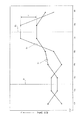
即ち、図7に示すように、各かしめ部101〜108の凸部111〜118によって形成される隙間は、第1かしめ部104,105の隙間d21が最も大きく、第2かしめ部101,108及び第1かしめ部104,105側の第3かしめ部103,106の隙間d22,d23、第2かしめ部101,108側の第3かしめ部102,107の隙間d24の順に小さくなっている。
That is, as shown in FIG. 7, a gap formed by the
また、凹部側の観点からみると、第2かしめ部101,108の凹部(121,128)と上層のコアプレート片3O1の第1かしめ部104,105の凸部114,115との間の円周方向Cの隙間d21を、第3かしめ部102,103,106,107の凹部122,123,126,127と上層のコアプレート片3O1の第3かしめ部102,103,106,107の凸部112,113,116,117との間の円周方向Cの前記隙間d23,d24よりも大きくした。また、第1かしめ部104,105の凹部124,125と上層のコアプレート片3Oの第2かしめ部101,108の凸部111,118との間の円周方向Cの隙間d22の大きさを、第2かしめ部101,108の凹部121,128と上層のコアプレート片3O1の第1かしめ部104,105の凸部114,115との間の円周方向Cの隙間d21以下でかつ、第3かしめ部102,103,106,107の凹部122,123,126,127と他層のコアプレート片3の第3かしめ部102,103,106,107の凸部112,113,116,117との間の円周方向Cの隙間d23,d24以上となるように設定した、ともいえる。
Further, from the viewpoint of the concave portion side, the concave portions (12 1 , 12 8 ) of the
なお、図7中のE1の範囲は、第1かしめ部104,105の凸部側の隙間d21の設定許容範囲であり、第2かしめ部101,108の凸部側の隙間d22の設定許容範囲E2と略略一致している。また、E3は、第3かしめ部102,107の凸部側の隙間d22,d23,d26,d27の設定許容範囲であり、これら第3かしめ部102,107の凸部側の隙間d22,d23,d26,d27は、第1かしめ部104,105に近いほどその隙間が大きく、積層方向に重なる前記コアプレート2の継ぎ目D2位置と、コアプレート片3Eの端部位置である継ぎ目D1との間の中間点で、その隙間が小さくなるように設定されている。
The range of E 1 in FIG. 7 is a set allowable range of the gap d 21 of the
ついで、本発明の実施形態に係るロータコア1の作用について説明をする。作業者は、ロータコア1を作成するにあたり、図1に示すように、保持器(不図示)にコアプレート片3を環状に並べてコアプレート2を形成すると共に、このコアプレート上に次のコアプレート片3を積層して行く。この時、保持器はコアプレートの層が変わる度に所定角度だけ回転させられるため、上記コアプレート2は、積層方向に隣接するコアプレート2とコアプレート片3の継ぎ目D1,D2の円周方向Cの位置が交互にずれるように積層される。また、このコアプレート2の層が変わる際にはプレスによってだぼかしめされるため、積層されたコアプレート2が積層方向に連結される。そして、このコアプレート2が規定枚数積層されてロータコア1が形成される。
Next, the operation of the
即ち、仮組されたコアプレート2がプレスされると、かしめ部10の直線部10aが締り嵌めによって嵌合し、コアプレート片3を積層方向に連結すると共に、これら積層された複数のコアプレート2によって1つのロータコア1が形成される。そして、作業者、このロータコア1の磁石嵌挿穴6にネオジム磁石を挿入してロータとすると共に、このロータを組み込んで回転電機を作成する。
That is, when the temporarily assembled core plate 2 is pressed, the
ところで、回転電機に電力が供給されて上記ロータが回転すると、ロータコア1のコアプレート片3には、それぞれロータの回転速度に応じた遠心力が発生する。この遠心力が発生すると、図5に示すように、各コアプレート片3は、重なり合うコアプレート片3O,3Eがコアプレート2の円周方向Cに離れる方向(例えば、コアプレート片3Eの場合、図中M方向)に移動しようとする。すると、これら重なり合うコアプレート片3O,3Eを連結するかしめ部10では、隙間嵌めであった円弧部10bの壁部11b,12b間の隙間d2がコアプレート片3O,3Eの円周方向へのズレもしくは弾性変形によって無くなる。そして、かしめ部10に掛る遠心力の円周方向成分の力は、これら円弧状の壁部11b,12bが当接することによって受けられる。
By the way, when electric power is supplied to the rotating electrical machine and the rotor rotates, a centrifugal force corresponding to the rotational speed of the rotor is generated in the
この時、コアプレート片3Eに設けられた第1乃至第3かしめ部101〜108は、その凸部111〜118と他層のコアプレート片3O1,3O2のかしめ部101〜108の凹部121〜128と間に形成される隙間d21〜d24が狭いかしめ部101〜108から、上記円弧状の壁部11b,12bが当接する。具体的には、第2かしめ部側の第3かしめ部102,107、第1かしめ部104,105側の第3かしめ部103,106及び第2かしめ部101,108、そして、最後に第1かしめ部104,105の壁部11b,12bが当接し、上記円周方向成分の力は、各かしめ部101〜108にて分散して受けられる。
At this time, the first to third crimping
このように、かしめ部10に掛る遠心力を、円弧状に形成された壁部11b,12bの当接によって受けると、応力集中しないために大きな応力(遠心力)にも耐えることができる。また、かしめ部10の半径方向の嵌め合いを締り嵌めとし、この遠心力に基づいて発生する応力を受ける円弧部10bを隙間嵌めとしたことによって、円弧部10bには、締り嵌めによる引っ張りの残留応力が発生しておらず、より大きな遠心力に耐えることができる。
As described above, when the centrifugal force applied to the
更に、上記締りはめとなる部分をコアプレート片3の接線方向に直線状に延接された直線部10aによって構成したことにより、この直線部で締り嵌めによる残留応力を均等に受けることができると共に、重なり合うコアプレート片3O,3Eの円周方向へのズレを容易にしている。そして、これら遠心力に基づく応力を受ける部分と、残留応力が生じる部分とを分けることによって、かしめ部が大きな遠心力にも耐えられるようになり、ロータコア1の回転強度を向上させることができる。
Furthermore, since the portion to be the interference fit is constituted by the
更に、1つのコアプレート片3に複数のかしめ部を設け、これら複数のかしめ部のうち、積層方向に重なるコアプレート3Oの継ぎ目D2位置及び同じ層コアプレート3Eの継ぎ目D1位置に隣接する第1及び第2かしめ部104,105,101,108が、他層のコアプレート片3O1,3O2のかしめ部104,105,101,108と嵌合して形成する上記隙間d21,d22を、第3かしめ部102,103,106,107が、他層の第かしめ部102,103,106,107と嵌合して形成する隙間d23,d24よりも大きくすることによって、かしめ部101〜108の位置に依らず、1つのコアプレート片3の各かしめ部101〜108に掛る応力の差を、出来る限り少なくすることができる。
Further, a plurality of caulking portions in one
また、第1かしめ部104,105の凸部114,115と、上層のコアプレート片3O1の第2かしめ部101,108の凹部121,128との間の隙間d21を、他の隙間d22〜d24よりも大きくしたことによって、かしめ部101〜108の中で、最も大きな引っ張り応力が働く第1かしめ部104,105の凸部114,115に生じる応力を効果的に低減することができる。
Further, the gap between the
これにより、かしめ部の強度が向上し、コアプレート2を分割したロータコア1においても、径方向にコンパクトな構成で必要な回転強度を達成することができる。また、コアプレート2の厚さも薄く形成することができるので、ロータコア1に発生する渦電流も小さく抑えることができ、歩留まりが高く効率の良い回転電機を、上記ロータコア1を用いて作成することができる。
Thereby, the strength of the caulking portion is improved, and even in the
なお、本実施形態においては、上記かしめ部10の凸部11と、他の層のコアプレート片3O1,3O2のかしめ部10の凹部12との間の隙間d2の大きさを調節するのに、該かしめ部の凹部12の幅Wc1を一定にすると共に、各かしめ部10の凸部11の幅Wc21〜Wc28を変更していたが、当然にかしめ部10の凸部11の幅Wc2を一定にすると共に、各かしめ部の凹部12の幅Wc1を変更しても良い。また、図9に示すように、凸部11の凹部12に対する位置をずらし、ロータコア1が回転した際に、かしめ部の凸部及び凹部が当接する側の隙間d2だけを調節するようにしても良い。
In the present embodiment, the size of the gap d 2 between the
更に、上記かしめ部10は、円弧部10bを2つの曲率の円弧によって形成したり、曲率の小さな1つの大きな円弧によって形成したりして、直線部10aを長く形成するようにしても良い。
Further, the
また、本実施形態において、かしめ部10は、円周方向の長さが半径方向の長さよりも長く形成されていたが、半径方向の長さを円周方向の長さよりも長く形成しても良い。
Further, in the present embodiment, the
更に、上述したかしめ構造は、どのように組み合わされても良いと共に、IPMモータに限らずどのような回転電機のロータコアに使用されても良いことは当然である。 Furthermore, the above-described caulking structure may be combined in any way, and naturally it is not limited to the IPM motor and may be used for the rotor core of any rotating electrical machine.
1 ロータコア
2 コアプレート
3 コアプレート片
104,105 第1かしめ部
101,108 第2かしめ部
102,103,106,107 第3かしめ部
10a 締り嵌めとなる部分(直線部)
10b 隙間嵌めとなる部分(円弧部)
11 凸部
114,115 第1かしめ部の凸部
111,118 第2かしめ部の凸部
112,113,116,117 第3かしめ部の凸部
12 凹部
124,125 第1かしめ部の凹部
121,128 第2かしめ部の凹部
122,123,126,127 第3かしめ部の凹部
Wr1 凹部のコアプレート半径方向の幅
Wr2 凸部のコアプレート半径方向の幅
Wc1 凹部のコアプレート円周方向の幅
Wc2 凸部のコアプレート円周方向の幅
d2 隙間
d21 第1かしめ部の凸部と、凸部側の他層のコアプレート片の第2かしめ部の凹部と間の隙間
d22 第1かしめ部の凹部と、凹部側の他層のコアプレート片の第2かしめ部の凸部と間の隙間
d23,d24 第3かしめ部と他層のコアプレート片の第3かしめ部との間の隙間
D1,D2 継ぎ目
R 半径方向
C 円周方向
DESCRIPTION OF
10b Part (arc part) which becomes gap fitting
11
Claims (2)
前記コアプレート片は、積層方向一方側の面に形成された凸部と、積層方向他方側で前記凸部と同じ位置に形成され、前記コアプレート片が積層された際に積層方向他方側の面と接する他層のコアプレート片の凸部と嵌合する凹部と、を有するかしめ部を、前記コアプレートの円周方向に複数備え、
前記複数のかしめ部を、前記他層のコアプレート片の継ぎ目位置に隣接する第1かしめ部と、前記コアプレート片の端部に設けられた第2かしめ部と、これら第1及び第2かしめ部の間に形成される第3かしめ部とから構成すると共に、前記第1かしめ部の凹部が、前記他層のコアプレート片の前記第2かしめ部の凸部に嵌合し、前記第2かしめ部の凹部が、前記他層のコアプレート片の前記第1かしめ部の凸部に嵌合し、前記第3かしめ部の凹部が、前記他層のコアプレート片の前記第3かしめ部の凸部に嵌合するように前記コアプレートを積層し、
これら第1乃至第3のかしめ部の凸部及び凹部の嵌め合いを、前記コアプレートの半径方向では締り嵌めとすると共に、前記コアプレートの円周方向では所定の隙間を存する隙間嵌めとしかつ、前記第2かしめ部の凹部と前記他層のコアプレート片の前記第1かしめ部の凸部との間の円周方向の隙間を、前記第3かしめ部の凹部と前記他層のコアプレート片の前記第3かしめ部の凸部との間の円周方向の隙間よりも大きくした、 ことを特徴とする回転電機のロータコア。 A plurality of annular core plates are stacked, and arc-shaped core plate pieces obtained by equally dividing the core plate are connected to form one layer of the core plate, and the core plate of the core plate In the rotor core of the rotating electrical machine configured so that the circumferential position of the seam of the piece is alternately different for each layer,
The core plate piece is formed at the same position as the convex portion on the one side in the stacking direction and the convex portion on the other side in the stacking direction, and when the core plate piece is stacked, A plurality of caulking portions having a concave portion that fits with the convex portion of the core plate piece of the other layer in contact with the surface in the circumferential direction of the core plate;
The plurality of caulking portions include a first caulking portion adjacent to a joint position of the core plate piece of the other layer, a second caulking portion provided at an end portion of the core plate piece, and the first and second caulking portions. And a concave portion of the first caulking portion is fitted to a convex portion of the second caulking portion of the core plate piece of the other layer, and the second caulking portion is formed between the second caulking portions. A concave portion of the caulking portion fits into a convex portion of the first caulking portion of the core plate piece of the other layer, and a concave portion of the caulking portion of the third plate is a portion of the third caulking portion of the core plate piece of the other layer. Laminate the core plate so as to fit into the convex part,
The fitting of the convex portion and the concave portion of the first to third caulking portions is an interference fit in the radial direction of the core plate, and a gap fit with a predetermined gap in the circumferential direction of the core plate, and A circumferential clearance between the concave portion of the second caulking portion and the convex portion of the first caulking portion of the core plate piece of the other layer is defined as a concave portion of the third caulking portion and the core plate piece of the other layer. A rotor core for a rotating electrical machine, wherein the rotor core is larger than a circumferential clearance between the third caulking portion and the convex portion.
請求項1記載の回転電機のロータコア。 The size of the gap in the circumferential direction between the concave portion of the first caulking portion and the convex portion of the second caulking portion of the core plate piece of the other layer is set as the concave portion of the second caulking portion and the other layer. A circumferential gap between the convex portion of the first caulking portion of the core plate piece and a concave portion of the third caulking portion and a convex portion of the third caulking portion of the core plate piece of the other layer; Set to be greater than or equal to the circumferential clearance between
The rotor core of the rotary electric machine according to claim 1.
Priority Applications (1)
| Application Number | Priority Date | Filing Date | Title |
|---|---|---|---|
| JP2010258356A JP2012110164A (en) | 2010-11-18 | 2010-11-18 | Rotor core for rotary electric machine |
Applications Claiming Priority (1)
| Application Number | Priority Date | Filing Date | Title |
|---|---|---|---|
| JP2010258356A JP2012110164A (en) | 2010-11-18 | 2010-11-18 | Rotor core for rotary electric machine |
Publications (1)
| Publication Number | Publication Date |
|---|---|
| JP2012110164A true JP2012110164A (en) | 2012-06-07 |
Family
ID=46495141
Family Applications (1)
| Application Number | Title | Priority Date | Filing Date |
|---|---|---|---|
| JP2010258356A Pending JP2012110164A (en) | 2010-11-18 | 2010-11-18 | Rotor core for rotary electric machine |
Country Status (1)
| Country | Link |
|---|---|
| JP (1) | JP2012110164A (en) |
-
2010
- 2010-11-18 JP JP2010258356A patent/JP2012110164A/en active Pending
Similar Documents
| Publication | Publication Date | Title |
|---|---|---|
| JP5510285B2 (en) | Rotor core of rotating electrical machine | |
| US8581468B2 (en) | Stator for electric rotating machine | |
| JP5326642B2 (en) | Rotating electric machine and method of manufacturing rotating electric machine | |
| JP2010104160A (en) | Dual rotor motor and manufacturing method therefor | |
| US20130106234A1 (en) | Rotor for permanent magnet type rotating electrical machine, permanent magnet type rotating electrical machine, and method for manufacturing rotor | |
| JP5609619B2 (en) | Rotating electric machine stator core | |
| CN110089005A (en) | The rotor and rotating electric machine of rotating electric machine | |
| JP2010148329A (en) | Stator core structure of rotating electric machine | |
| WO2014208582A1 (en) | Synchronous rotor for rotary electrical machine and method for manufacturing synchronous rotor for rotary electrical machine | |
| WO2017195498A1 (en) | Rotor and rotary electric machine | |
| JP2013070494A (en) | Stator core and motor | |
| JP2012110163A (en) | Rotor core for rotary electric machine | |
| JP5633507B2 (en) | Rotating electrical machine rotor | |
| JP5900180B2 (en) | Rotor core of rotating electrical machine | |
| JP7188588B2 (en) | Rotor and rotor manufacturing method | |
| JP2005117796A (en) | Rotating electrical machine rotor | |
| JP2012110164A (en) | Rotor core for rotary electric machine | |
| JP2007143257A (en) | Laminated iron core and method for manufacturing the same | |
| JP4295691B2 (en) | Rotating machine armature | |
| JP7799162B2 (en) | Split stator and rotating electric machine | |
| JP2012075232A (en) | Stator for rotating electric machine and method of manufacturing the same | |
| JP2012110162A (en) | Rotor core for rotary electric machine | |
| EP3723241B1 (en) | Rotor core for rotating electric machine and method for manufacturing rotor core for rotating electric machine | |
| JP2006325295A (en) | Stator | |
| JP2012249354A (en) | Rotor for rotary electric machine |