JP2012116253A - コンソールボックス - Google Patents
コンソールボックス Download PDFInfo
- Publication number
- JP2012116253A JP2012116253A JP2010266006A JP2010266006A JP2012116253A JP 2012116253 A JP2012116253 A JP 2012116253A JP 2010266006 A JP2010266006 A JP 2010266006A JP 2010266006 A JP2010266006 A JP 2010266006A JP 2012116253 A JP2012116253 A JP 2012116253A
- Authority
- JP
- Japan
- Prior art keywords
- inner box
- outer panel
- box
- engaging
- console box
- Prior art date
- Legal status (The legal status is an assumption and is not a legal conclusion. Google has not performed a legal analysis and makes no representation as to the accuracy of the status listed.)
- Granted
Links
- 238000003780 insertion Methods 0.000 claims abstract description 10
- 230000037431 insertion Effects 0.000 claims abstract description 10
- 238000010079 rubber tapping Methods 0.000 abstract description 16
- JOYRKODLDBILNP-UHFFFAOYSA-N Ethyl urethane Chemical compound CCOC(N)=O JOYRKODLDBILNP-UHFFFAOYSA-N 0.000 description 9
- 239000000463 material Substances 0.000 description 6
- 239000011347 resin Substances 0.000 description 6
- 229920005989 resin Polymers 0.000 description 6
- 239000004743 Polypropylene Substances 0.000 description 2
- 229920001155 polypropylene Polymers 0.000 description 2
- 238000003466 welding Methods 0.000 description 2
- 229920000122 acrylonitrile butadiene styrene Polymers 0.000 description 1
- 238000004378 air conditioning Methods 0.000 description 1
- 230000015572 biosynthetic process Effects 0.000 description 1
- 230000001143 conditioned effect Effects 0.000 description 1
- -1 polypropylene Polymers 0.000 description 1
- 150000003673 urethanes Chemical class 0.000 description 1
Images


Landscapes
- Vehicle Step Arrangements And Article Storage (AREA)
Abstract
【解決手段】アウターパネル12、14とインナーボックス30を係合させるクリップ部20及びクリップ挿入部40と、タッピングスクリュー62が挿入される取付穴34を有する取付部32と、タッピングスクリュー62が挿入される係合穴を有する係合部22と、取付部32と係合部22がナットスプリングを介しタッピングスクリュー62で組付けられており、左右のアウターパネル12,14のタッピングスクリュー62の組付け方向は同一方向である。
【選択図】図2
Description
通常このコンソールボックスは、アウターパネルとインナーボックスを同一の樹脂材料(例えばPP(ポリプロピレン))で形成し、インナーボックス(又はアウターパネル)側にリブを形成し、アウターパネル(又はインナーボックス)と振動溶着により一体化するものが一般的である。
そのため、組付け作業に時間が掛かり、コストアップになってしまうという問題があった。
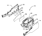
アウターパネル12、13には、上端側にクリップ部20、下端側には、係合部22が形成されている。この係合部22には、ナットスプリング60取付けられ、インナーボックス30の取付部32より挿入されたネジとしてのタッピングスクリュー62により固定される構成となっている。この固定箇所は、左右に3箇所ずつ設けられ、複数箇所で固定さ列構成となっている。
また、アウターパネル12に内側にはウレタン50が、インナーボックス30のダクト形成部18には、ウレタン52が貼り付けられる。
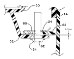
アウターパネル12、14は、上端側でアウターパネル12,14に設けられた、クリップ部20が、インナーボックス30に設けられたクリップ挿入部40のクリップ挿入穴42に挿入され固定される。一方下端側は、アウターパネル12、14に設けられた係合部22にナットスプリング60が取付けられ、インナーボックス30に設けられた取付部32に挿入されたタッピングスクリュー62が、ナットスプリング60が螺合されている。係合部22及び取付部32は、コンソールボックス10に対し水平方向に形成されており、これらに対しタッピングスクリュー62は、左右とも垂直方向から組付けられるため、コンソールボックス10を回転させることなく組付け作業を行うことができる。
アウターパネル14の係合部24を有する係合部22に取付られたナットスプリング60に対し、インナーボックス30の取付部32から取付穴34を通してタッピングスクリュー62を挿入する。そして、このタッピングスクリュー62とナットスプリング60とを螺合する。
12 アウターパネル
14 アウターパネル
16 ダクト形成リブ
18 ダクト部
20 クリップ部
22 係合部
24 係合穴
30 インナーボックス
32 取付部
34 取付穴
40 クリップ挿入部
42 クリップ挿入穴
50 ウレタン
52 ウレタン
60 ナットスプリング
62 タッピングスクリュー(ネジ)
70 コンソールボックス
72 アウターパネル
74 クリップ取付部
76 取付座
80 インナーボックス
82 クリップ挿入部
84 取付部
90 クリップ
92 タッピングスクリュー
94 ナットスプリング
Claims (3)
- 少なくとも左右2枚のアウターパネルとインナーボックスを組みつけて成るコンソールボックスにおいて、アウターパネル及びインナーボックスの上端側に設けられ、アウターパネルとインナーボックスを係合させるクリップ部及びクリップ挿入部と、
アウターパネル及びインナーボックスの下端側に設けられ、アウターパネルまたはインナーボックスから突出し、ネジが挿入される取付穴を有する取付部と、
アウターパネル及びインナーボックスの下端側で、前記取付部より上部側に設けられ、アウターパネルまたはインナーボックスから突出した前記ネジが挿入される係合穴を有する係合部と、
前記係合部に取付けられたナットスプリングとを有し、
前記取付部と前記係合部が前記ナットスプリングを介し前記ネジで組付けられており、左右の前記アウターパネルの前記ネジの組付け方向は同一方向であることを特徴とするコンソールボックス。 - 前記アウターパネル及び前記インナーボックスから突出させて設けられた、前記取付部と前記係合部は、左右にそれぞれ複数箇所設けられると共に、隙間を設け組付けられていることを特徴とする請求項1に記載のコンソールボックス。
- 前記取付部と前記係合部の隙間は、0mm〜2.0mmであることを特徴とする請求項2に記載のコンソールボックス。
Priority Applications (1)
| Application Number | Priority Date | Filing Date | Title |
|---|---|---|---|
| JP2010266006A JP5494442B2 (ja) | 2010-11-30 | 2010-11-30 | コンソールボックス |
Applications Claiming Priority (1)
| Application Number | Priority Date | Filing Date | Title |
|---|---|---|---|
| JP2010266006A JP5494442B2 (ja) | 2010-11-30 | 2010-11-30 | コンソールボックス |
Publications (2)
| Publication Number | Publication Date |
|---|---|
| JP2012116253A true JP2012116253A (ja) | 2012-06-21 |
| JP5494442B2 JP5494442B2 (ja) | 2014-05-14 |
Family
ID=46499651
Family Applications (1)
| Application Number | Title | Priority Date | Filing Date |
|---|---|---|---|
| JP2010266006A Active JP5494442B2 (ja) | 2010-11-30 | 2010-11-30 | コンソールボックス |
Country Status (1)
| Country | Link |
|---|---|
| JP (1) | JP5494442B2 (ja) |
Cited By (2)
| Publication number | Priority date | Publication date | Assignee | Title |
|---|---|---|---|---|
| US9847630B1 (en) | 2017-02-09 | 2017-12-19 | Sumitomo Wiring Systems, Ltd. | Locking and retaining structure for attaching fuse box to battery tray |
| KR102224366B1 (ko) * | 2019-10-24 | 2021-03-09 | 주식회사 서연이화 | 차량용 콘솔 암레스트 |
Citations (6)
| Publication number | Priority date | Publication date | Assignee | Title |
|---|---|---|---|---|
| JPH0562349U (ja) * | 1992-01-30 | 1993-08-20 | 小島プレス工業株式会社 | 樹脂製成形品の結合構造 |
| JPH06323317A (ja) * | 1993-02-24 | 1994-11-25 | Illinois Tool Works Inc <Itw> | Uナット |
| JP2006176009A (ja) * | 2004-12-22 | 2006-07-06 | Kasai Kogyo Co Ltd | ドアトリムにおけるプルハンドルフィニッシャーの取付構造 |
| JP2007137391A (ja) * | 2005-11-22 | 2007-06-07 | Daikyoo Nishikawa Kk | センターコンソール |
| JP2010185532A (ja) * | 2009-02-13 | 2010-08-26 | Kanto Auto Works Ltd | 隙間調整ボルトナット及び隙間調整ボルトナットを有する隙間調整具 |
| JP2010201855A (ja) * | 2009-03-05 | 2010-09-16 | Kojima Press Industry Co Ltd | 発泡シートの接合方法 |
-
2010
- 2010-11-30 JP JP2010266006A patent/JP5494442B2/ja active Active
Patent Citations (6)
| Publication number | Priority date | Publication date | Assignee | Title |
|---|---|---|---|---|
| JPH0562349U (ja) * | 1992-01-30 | 1993-08-20 | 小島プレス工業株式会社 | 樹脂製成形品の結合構造 |
| JPH06323317A (ja) * | 1993-02-24 | 1994-11-25 | Illinois Tool Works Inc <Itw> | Uナット |
| JP2006176009A (ja) * | 2004-12-22 | 2006-07-06 | Kasai Kogyo Co Ltd | ドアトリムにおけるプルハンドルフィニッシャーの取付構造 |
| JP2007137391A (ja) * | 2005-11-22 | 2007-06-07 | Daikyoo Nishikawa Kk | センターコンソール |
| JP2010185532A (ja) * | 2009-02-13 | 2010-08-26 | Kanto Auto Works Ltd | 隙間調整ボルトナット及び隙間調整ボルトナットを有する隙間調整具 |
| JP2010201855A (ja) * | 2009-03-05 | 2010-09-16 | Kojima Press Industry Co Ltd | 発泡シートの接合方法 |
Cited By (2)
| Publication number | Priority date | Publication date | Assignee | Title |
|---|---|---|---|---|
| US9847630B1 (en) | 2017-02-09 | 2017-12-19 | Sumitomo Wiring Systems, Ltd. | Locking and retaining structure for attaching fuse box to battery tray |
| KR102224366B1 (ko) * | 2019-10-24 | 2021-03-09 | 주식회사 서연이화 | 차량용 콘솔 암레스트 |
Also Published As
| Publication number | Publication date |
|---|---|
| JP5494442B2 (ja) | 2014-05-14 |
Similar Documents
| Publication | Publication Date | Title |
|---|---|---|
| JP2014008897A (ja) | ドアミラー | |
| US8459715B2 (en) | Box support structure for instrument panel | |
| US20130058014A1 (en) | Instrument panel assembly | |
| JP2013136319A (ja) | 車両用ドア | |
| JP2018064351A (ja) | 固定構造、および、電気接続箱 | |
| JP5494442B2 (ja) | コンソールボックス | |
| JP5391812B2 (ja) | 車両用スピーカ装置 | |
| JP2015101231A (ja) | 車体側部構造 | |
| JP5821682B2 (ja) | 電装部品のガタツキ防止構造 | |
| JP2016116250A (ja) | グロメット | |
| JP5071804B2 (ja) | 車両用インストルメントパネル前端部組付け構造 | |
| JP6260820B2 (ja) | インストルメントパネル構造 | |
| JP2014111417A (ja) | ハーネスクランプ | |
| KR101514888B1 (ko) | 공차흡수 브래킷 | |
| JP6805591B2 (ja) | 車両用インストルメントパネル | |
| JP2014162332A (ja) | 車体構造 | |
| JP6213827B2 (ja) | インストルメントパネル側部及びフロントピラートリム下部の合わせ部構造 | |
| JP6601733B2 (ja) | 車両用空調ダクトの取付部構造 | |
| JP5200832B2 (ja) | サイドマッドガードの取付構造 | |
| JP2016055682A (ja) | 車両前部構造 | |
| JP6173202B2 (ja) | 車両用ガーニッシュ | |
| JP6547680B2 (ja) | 車両側部構造 | |
| JP2021178578A (ja) | 車両部品の固定構造 | |
| JP6746249B2 (ja) | 部品取付構造 | |
| JP2016137782A (ja) | フロントピラー構造 |
Legal Events
| Date | Code | Title | Description |
|---|---|---|---|
| A621 | Written request for application examination |
Free format text: JAPANESE INTERMEDIATE CODE: A621 Effective date: 20130125 |
|
| A977 | Report on retrieval |
Free format text: JAPANESE INTERMEDIATE CODE: A971007 Effective date: 20140122 |
|
| TRDD | Decision of grant or rejection written | ||
| A01 | Written decision to grant a patent or to grant a registration (utility model) |
Free format text: JAPANESE INTERMEDIATE CODE: A01 Effective date: 20140204 |
|
| A61 | First payment of annual fees (during grant procedure) |
Free format text: JAPANESE INTERMEDIATE CODE: A61 Effective date: 20140217 |
|
| R150 | Certificate of patent or registration of utility model |
Ref document number: 5494442 Country of ref document: JP Free format text: JAPANESE INTERMEDIATE CODE: R150 |