JP2012117314A - Private part washing device - Google Patents
Private part washing device Download PDFInfo
- Publication number
- JP2012117314A JP2012117314A JP2010269493A JP2010269493A JP2012117314A JP 2012117314 A JP2012117314 A JP 2012117314A JP 2010269493 A JP2010269493 A JP 2010269493A JP 2010269493 A JP2010269493 A JP 2010269493A JP 2012117314 A JP2012117314 A JP 2012117314A
- Authority
- JP
- Japan
- Prior art keywords
- nozzle
- cap
- advance
- retreat
- main body
- Prior art date
- Legal status (The legal status is an assumption and is not a legal conclusion. Google has not performed a legal analysis and makes no representation as to the accuracy of the status listed.)
- Granted
Links
Images



Landscapes
- Bidet-Like Cleaning Device And Other Flush Toilet Accessories (AREA)
Abstract
【課題】部品点数の削減を図る。
【解決手段】局部洗浄装置は、前端が進退口15として開口された収容室13を有するハウジング10と、収容室13内に収容される格納位置と、吐水口32を進退口15から収容室13の前方へ進出させる洗浄位置との間で進退可能なノズル30と、ノズル30の嵌合凹部35に対して着脱可能なキャップ40とを備える。キャップ40は、嵌合凹部35に装着された状態でノズル30の前端面を覆い隠す本体部41と、本体部41の外周縁に沿って形成され、キャップ40が嵌合凹部35に装着され且つノズル30が格納位置へ後退した状態で、ノズル30の前端外周縁と進退口15の開口縁との隙間を塞ぐフランジ部43を備える。
【選択図】図1To reduce the number of parts.
A local cleaning device includes a housing having a housing chamber having a front end opened as an advance / retreat port, a storage position accommodated in the storage chamber, and a water discharge port from the advance / retreat port to the storage chamber. A nozzle 30 that can move forward and backward with respect to the cleaning position that advances forward, and a cap 40 that can be attached to and detached from the fitting recess 35 of the nozzle 30. The cap 40 is formed along the outer peripheral edge of the main body 41 and the main body 41 that covers the front end surface of the nozzle 30 in a state where the cap 40 is mounted in the fitting concave 35. A flange portion 43 that closes the gap between the outer peripheral edge of the front end of the nozzle 30 and the opening edge of the advance / retreat port 15 in a state where the nozzle 30 is retracted to the storage position is provided.
[Selection] Figure 1
Description
本発明は、局部洗浄装置に関するものである。 The present invention relates to a local cleaning apparatus.
特許文献1には、前端が進退口として開口された収容室を有するハウジングと、収容室内に収容される位置と、吐水口を進退口から収容室の前方へ進出させる位置との間での進退を可能に設けられたノズルとを備えた局部洗浄装置が開示されている。この局部洗浄装置では、収容室の内面とノズルの外面との間には、ノズルの進退動作の円滑化を図るために、ノズルの外面と収容室の内面との間にクリアランスが設けられている。このように収容室内にクリアランスが設けられていると、ノズルを収容室に収容した状態で、進退口から収容室内に汚水や汚物が侵入することが懸念される。 In Patent Document 1, a housing having a housing chamber whose front end is opened as an advance / retreat port, a position accommodated in the accommodation chamber, and a position where the water discharge port is advanced from the advance / retreat port to the front of the accommodation chamber. There is disclosed a local cleaning device including a nozzle provided to enable the above. In this local cleaning device, a clearance is provided between the inner surface of the storage chamber and the outer surface of the nozzle in order to facilitate the forward and backward movement of the nozzle between the outer surface of the nozzle and the inner surface of the storage chamber. . When the clearance is provided in the storage chamber in this manner, there is a concern that sewage or filth may enter the storage chamber from the advance / retreat port in a state where the nozzle is stored in the storage chamber.
そこで、特許文献1の局部洗浄装置には、収容室内に汚物や汚水が浸入するのを防止する手段として、シャッターを用いて進退口を閉塞する構造が採用されている。シャッターは、進退口を閉塞する閉塞位置と、進退口を開放させる開放位置との間で変位可能に支持されており、ノズルが前方へ進出するときには、シャッターがノズルに押されることによって閉塞位置から開放位置へ変位する。そして、ノズルが収容室内に収容されると、シャッターは、復帰バネの弾力によって開放位置から閉塞位置へ復帰するようになっている。 In view of this, the local cleaning device disclosed in Patent Document 1 employs a structure in which the advancing / retreating opening is closed using a shutter as means for preventing filth and filthy water from entering the housing chamber. The shutter is supported so as to be displaceable between a closed position for closing the advance / retreat opening and an open position for opening the advance / retreat opening, and when the nozzle advances forward, the shutter is pushed by the nozzle to move from the closed position. Displace to open position. When the nozzle is accommodated in the accommodation chamber, the shutter is returned from the open position to the closed position by the elasticity of the return spring.
特許文献1に記載されたシャッター構造は、シャッターの他に、シャッターを開口部の開口縁に支持するための左右一対の軸部材と、左右一対の付勢バネが必要であるため、部品点数が多いという問題がある。
本発明は上記のような事情に基づいて完成されたものであって、部品点数の削減を図ることを目的とする。
In addition to the shutter, the shutter structure described in Patent Document 1 requires a pair of left and right shaft members for supporting the shutter on the opening edge of the opening and a pair of left and right biasing springs. There is a problem that there are many.
The present invention has been completed based on the above-described circumstances, and an object thereof is to reduce the number of parts.
上記の目的を達成するための手段として、請求項1の発明は、前端が進退口として開口された収容室を有するハウジングと、洗浄水を吐出する吐水口を有し、少なくとも前記吐水口の形成領域を前記収容室内に収容させる格納位置と、前記吐水口を前記進退口から前記収容室の前方へ進出させる洗浄位置との間での進退を可能に設けられたノズルと、前記ノズルにおける前記吐水口よりも前方の位置に形成した嵌合部に対し、着脱を可能とされたキャップとを備え、前記キャップは、前記キャップが前記嵌合部に装着された状態で前記ノズルの前端面を前方から覆い隠す本体部と、前記本体部の外周縁に沿って形成され、前記キャップが前記嵌合部に装着され且つ前記ノズルが格納位置へ後退した状態で、前記ノズルの前端外周縁と前記進退口の開口縁との間の隙間を塞ぐフランジ部とを備えて構成されているところに特徴を有する。 As means for achieving the above object, the invention of claim 1 includes a housing having a housing chamber whose front end is opened as an advancement / retraction opening, a water discharge port for discharging cleaning water, and at least forming the water discharge port. A nozzle provided so as to be able to advance and retreat between a storage position where the region is accommodated in the accommodation chamber and a cleaning position where the water outlet is advanced from the advancement / retraction opening to the front of the accommodation chamber; A cap that is attachable to and detachable from the fitting portion formed at a position in front of the water mouth, and the cap moves the front end surface of the nozzle forward in a state where the cap is attached to the fitting portion. A main body part that covers from the outer peripheral edge of the main body part, the front end outer peripheral edge of the nozzle and the forward / backward movement of the nozzle with the cap attached to the fitting part and the nozzle retracted to the storage position. Characterized in place being constituted by a flange portion which closes the gap between the opening edge of the.
請求項2の発明は、請求項1に記載のものにおいて、前記キャップが前記嵌合部に装着され且つ前記ノズルが格納位置へ後退した状態では、前記フランジ部の前面における外周縁が、前記ハウジングの前面に対してほぼ面一状に連なるような形態とされているところに特徴を有する。 According to a second aspect of the present invention, in the first aspect of the present invention, in the state where the cap is attached to the fitting portion and the nozzle is retracted to the retracted position, the outer peripheral edge of the front surface of the flange portion is the housing. It is characterized in that it is configured so as to be substantially flush with the front surface.
請求項3の発明は、請求項1または請求項2に記載のものにおいて、前記フランジ部の後面における外周縁部と、前記ハウジングの前面における前記進退口の開口縁部には、前記ノズルの進退方向に対して傾斜し、且つ互いに密着可能なテーパ面が形成されているところに特徴を有する。 According to a third aspect of the present invention, in the first or second aspect of the present invention, the outer peripheral edge portion of the rear surface of the flange portion and the opening edge portion of the forward / backward opening of the front surface of the housing may be moved forward and backward. It is characterized in that tapered surfaces that are inclined with respect to the direction and can be brought into close contact with each other are formed.
<請求項1の発明>
キャップが嵌合部に装着されてノズルが格納位置へ後退した状態では、ノズルの前端面が本体部で覆い隠されるとともに、フランジ部によってノズルの前端外周縁と進退口の開口縁との間の隙間が塞がれるので、収容室内への汚物の浸入を確実に防止できる。また、キャップが汚れた場合には、キャップを嵌合部から外して洗浄することができるので、衛生状態を良好に保つことができる。本発明によれば、ノズルにキャップを取り付けるだけで、収容室内への汚物の侵入を防止できるので、部品点数が少なくて済む。
<Invention of Claim 1>
When the cap is attached to the fitting portion and the nozzle is retracted to the retracted position, the front end surface of the nozzle is covered with the main body portion, and the flange portion between the front edge of the front end of the nozzle and the opening edge of the advance / retreat port Since the gap is closed, it is possible to reliably prevent entry of filth into the accommodation chamber. In addition, when the cap becomes dirty, the cap can be removed from the fitting portion and cleaned, so that the hygienic state can be kept good. According to the present invention, it is possible to prevent entry of filth into the accommodation chamber simply by attaching a cap to the nozzle, and therefore the number of components can be reduced.
<請求項2の発明>
キャップが嵌合部に装着されてノズルが格納位置へ後退した状態では、フランジ部の外周縁がハウジングの前面に対してほぼ面一状に連なるので、フランジ部の前面における外周縁とハウジングの前面との間には、汚物が残留し易い狭小凹部は生じない。したがって、キャップをノズルから外さなくても、フランジ部の外周縁とその近傍を、清掃によって清潔な状態に保つことができる。
<Invention of Claim 2>
When the cap is mounted on the fitting portion and the nozzle is retracted to the retracted position, the outer peripheral edge of the flange portion is substantially flush with the front surface of the housing, so the outer peripheral edge on the front surface of the flange portion and the front surface of the housing Narrow recesses in which dirt is likely to remain do not occur between the two. Therefore, the outer peripheral edge of the flange portion and its vicinity can be kept clean by cleaning without removing the cap from the nozzle.
<請求項3の発明>
ノズルが格納位置へ後退する過程で、進退方向への位置ずれや進退方向と交差する方向への位置ずれを生じたとしても、格納位置に到達する直前で、フランジ部のテーパ面とハウジングのテーパ面によってノズルの位置ずれが矯正され、双方のテーパ面同士が全周に亘って密着する。
<Invention of Claim 3>
Even if a position shift in the advancing / retreating direction or a position shifting in a direction crossing the advancing / retreating direction occurs in the process of moving the nozzle back to the storage position, the taper surface of the flange portion and the taper of the housing immediately before reaching the storage position. The nozzle position shift is corrected by the surface, and both tapered surfaces are in close contact with each other over the entire circumference.
<実施形態1>
以下、本発明を具体化した実施形態1を図1乃至図5を参照して説明する。本実施形態の局部洗浄装置は、洋式の便器本体(図示省略)の後端部に設けられ、合成樹脂製のハウジング10と、合成樹脂からなる左右一対のノズル30と、合成樹脂製のキャップ40とを備えている。ハウジング10は、便器本体に固定されるベースプレート11と、ベースプレート11の上面を覆うことにより収容室13を形成するカバー12とを備えて構成され、収容室13内には進退ガイド20が設けられている。
<Embodiment 1>
A first embodiment embodying the present invention will be described below with reference to FIGS. The local cleaning apparatus according to the present embodiment is provided at the rear end of a western-style toilet body (not shown), and includes a
ベースプレート11には、その前端縁から上方へ立ち上がる前板部14が形成されている。前板部14は平坦な板状をなし、前板部14の前面は、斜め下前方に面するように、つまり便鉢(図示省略)の内部に臨むように傾斜している。この傾斜した前板部14の板面(前面)は、ノズル30の進退方向と直角をなしている。そして、前板部14には、左右一対の貫通形態の進退口15が、ハウジング10の前面に開口するように形成されている。一対の進退口15は、形状と大きさが互いに同じであり、その開口形状は非円形である。図3,4に示すように、進退口15は、真円において水平な弦を境にして上下対称な一対の弓形部を除去した形状の第1開口領域15Aと、第1開口領域15Aの下側の弦に沿うように配され、下側の弦の全幅に亘る横長長方形の第2開口領域15Bとを、互いに連通して構成されている。
The
図1,2,4に示すように、ハウジング10(前板部14)の前面における進退口15の開口縁部には、前板部14の前面に対して傾斜した前面側テーパ面18(本発明の構成要件であるハウジング側のテーパ面)が、進退口15の開口縁の全領域(全周)に亘って連続して形成されている。この前面側テーパ面18は、ノズル30の進退方向に対して傾斜している。前板部14の板厚方向(前後方向)における前面側テーパ面18の形成領域は、前側のほぼ1/2の範囲に亘っている。そして、前板部14の板厚方向において、進退口15の開口面積は、前面側テーパ面18の前端(前板部14の前面)で最大となり、前面側テーパ面18の後端に向かって次第に開口面積が小さくなっている。
As shown in FIGS. 1, 2, and 4, the front edge of the front side of the housing 10 (front plate portion 14) has a front side
図4に示すように、進退ガイド20は、その内部に左右一対の細長いガイド孔21を有している。図1,2に示すように、ガイド孔21は、前方に向かって下り勾配となるように傾斜している。進退ガイド20の前端は、ハウジング10の前板部14よりも少し後方に位置し、ガイド孔21の前端は、前板部14の近傍において進退口15と対応するように開口している。図4に示すように、このガイド孔21の開口形状は、進退口15とほぼ同じであり、ガイド孔21の開口領域は進退口15よりも少し小さい。つまり、ガイド孔21の前端の開口部は、進退口15と概ね相似状をなしている。ガイド孔21の長さ方向(つまり、ノズル30の進退方向)は、ハウジング10の前板部14の板面(前面)と直角な方向となっている。この一対のガイド孔21内には、夫々、互いに独立して進退駆動される一対のノズル30が設けられている。
As shown in FIG. 4, the advance /
図1,2,4に示すように、ノズル30は、前端が開放された合成樹脂製の筒状本体31と、筒状本体31の前端の開口部に固着された合成樹脂製の閉止部材34とを備えて構成され、全体として前端が閉塞された細長い筒状をなしている。図1,2に示すように、筒状本体31の上面には、ノズル30の前端よりも少し後方の位置で開口する吐水口32が形成されている。この吐水口32からは洗浄水が上向きに吐出されるようになっている。図2,4に示すように、筒状本体31の下面には、ラック33が形成されている。ノズル30は、ラック33を駆動機構(図示省略)のピニオンに係合させた状態でガイド孔21に取り付けられ、駆動機構とガイド孔21の案内とにより、格納位置(図1を参照)と洗浄位置との間でノズル30及びノズル30の長さ方向と平行に進退移動(往復移動)するようになっている。
As shown in FIGS. 1, 2, and 4, the
図4に示すように、筒状本体31のうちラック33を除いた部分の長さ方向と直角な正面形状は、進退口15の第1開口領域15Aとほぼ同じ形状であり、その正面形状は第1開口領域15Aよりも僅かに小さい。また、ラック33の正面形状は、進退口15の第2開口領域15Bと対応するような方形をなし、第2開口領域15Bよりも少し小さい。このようにラック33を含むノズル30の正面形状は、進退口15の開口領域の全体と対応している。
As shown in FIG. 4, the front shape perpendicular to the length direction of the portion of the cylindrical
図1,2,4に示すように、閉止部材34は、筒状本体31の前端の開口を液密状に塞ぐように固着されている。閉止部材34の前面と筒状本体31の前端面とは、面一状に連なっている。閉止部材34には、その前面を凹ませた形態の嵌合凹部35(本発明の構成要件である嵌合部)が形成されている。図4に示すように、嵌合凹部35は、真円の上端側部分を弓形に切欠した非円形形状をなしている。
As shown in FIGS. 1, 2, and 4, the closing
図1に示すように、ノズル30が格納位置にある状態では、ノズル30の全体がガイド孔21の内部に収容され、ノズル30の前端は前板部14の後面よりも後方に位置する。ノズル30が洗浄位置(図2に示す状態から更にノズル30が斜め下前方へ進出した位置)へ進出した状態では、ノズル30の少なくとも吐水口32を含む前端部が進退口15を貫通してハウジング10の前方外部へ進出し、吐水口32が、便鉢の内部に位置して斜め前上方へ洗浄水を吐出するようになっている。尚、図2は、ノズル30が洗浄位置よりも少し後方(格納位置側)に位置している状態を示している。
As shown in FIG. 1, in a state where the
キャップ40は、合成樹脂製の単一部品として成形され、図1〜3,5に示すように、本体部41と嵌合凸部42とフランジ部43と後面側テーパ面44を一体に形成した形態となっている。本体部41は、進退口15の第1開口領域15A及びノズル30の筒状本体31と同一の形状(即ち、真円において水平な弦を境にして上下対称な一対の弓形部を除去した形状)をなす板状の第1閉塞部41Aと、第2開口領域15Bと同一であり且つラック33と対応する形状(即ち、横長の長方形)をなす板状の第2閉塞部41Bとからなる。第1閉塞部41Aの板厚寸法は第2閉塞部41Bの板厚寸法よりも大きく、第2閉塞部41Bの板厚寸法は、前板部14の板厚寸法(即ち、進退口15の貫通方向の寸法)よりも少し小さい寸法とされている。第1閉塞部41Aの前面と第2閉塞部41Bの前面とは面一状に連なっている。また、第1閉塞部41Aの前面と後面は、互いに平行をなしている。
The
図1,2,5に示すように、第1閉塞部41Aの後面には嵌合凸部42が形成されている。嵌合凸部42の形状は、ノズル30の嵌合凹部35と同じ形状であり、嵌合凸部42の大きさは嵌合凹部35よりも僅かに大きく設定されている。本体部41の外周には、その全周に亘って連続するようにフランジ部43が形成されている。フランジ部43の外周形状は本体部41と相似の形状であり、フランジ部43の前面は本体部41の前面に対して面一状に連なっている。また、フランジ部43の最大板厚寸法は、全周に亘って一定であり、第2閉塞部41Bの板厚寸法と同じ寸法である。
As shown in FIGS. 1, 2, and 5, a fitting
キャップ40は、嵌合凸部42を嵌合凹部35に圧入することによってノズル30の前端部に取り付けられ、嵌合凸部42の外周面と嵌合凹部35の内周面との間の摩擦抵抗により、キャップ40は取付け状態に保持される。また、キャップ40に対し嵌合凸部42と嵌合凹部35との間の摩擦抵抗を上回る前方への引張力を付与すると、キャップ40をノズル30から外すことができるようになっている。
The
図1,2に示すように、キャップ40をノズル30に取り付けた状態では、第1閉塞部41Aの後面が閉止部材34の前面及び筒状本体31の前端面に対してほぼ密着し、第1閉塞部41Aの外周面と筒状本体31の外周面とがほぼ面一状に連続する。つまり、キャップ40の本体部41は、ノズル30の前端面を前方から覆い隠すように位置する。また、第2閉塞部41Bは、前方からラック33と対応するように位置し、フランジ部43は、ノズル30の外周よりも外側へ全周に亘って張り出した状態となる。また、キャップ40の前面は、その全領域に亘って平坦状をなしているとともに、ノズル30の進退方向に対して直角をなす。
As shown in FIGS. 1 and 2, in the state where the
図1,2,5に示すように、フランジ部43の後面には、本体部41(第1閉塞部41A及び第2閉塞部41B)の後面に対して傾斜した後面側テーパ面44(本発明の構成要件であるノズル30側のテーパ面)が、フランジ部43の全領域(全周)に亘って連続して形成されている。この後面側テーパ面44は、前面側テーパ面18と同じく、ノズル30の進退方向に対して傾斜している。本体部41の後面に対する後面側テーパ面44の傾斜角度は、前板部14の前面に対する前面側テーパ面18の傾斜角度と同じ角度であり、後面側テーパ面44の傾斜の向きは前面側テーパ面18の傾斜の向きと平行である。フランジ部43(第2閉塞部41B)の板厚方向(前後方向)における後面側テーパ面44の形成範囲は、フランジ部43(第2閉塞部41B)の前面から後面に亘っている。
As shown in FIGS. 1, 2, and 5, on the rear surface of the
次に、本実施形態の作用を説明する。ノズル30が格納位置へ後退した状態では、図1に示すように、ノズル30の前端部を含む全体が、進退ガイド20のガイド孔21内に格納されるので、収容室13内に収容されることになる。進退ガイド20の前端面は前板部14の後面よりも後方に位置しているので、進退口15が開放されている場合には、進退口15から汚物が収容室13内に侵入する虞がある。また、ガイド孔21の内周とノズル30の外周との間には、ノズル30の進退動作を円滑に行わせるためにクリアランス45が確保されているので、収容室13内に侵入した汚物が、クリアランス45を通ってガイド孔21内に侵入し、ノズル30の外周やガイド孔21の内周に付着する虞もある。また、ガイド孔21とノズル30の隙間に侵入した汚物が乾燥して固化すると、ノズル30の進出動作に支障を来すことになる。
Next, the operation of this embodiment will be described. In the state in which the
そこで、本実施形態では、ノズル30の前端部にキャップ40を取り付けた。このキャップ40は、ノズル30が格納位置へ後退したときに、ノズル30の前端面を前方から覆い隠す本体部41と、ノズル30の前端外周縁と進退口15の開口縁との間の隙間を塞ぐフランジ部43とを備えており、進退口15の全開口領域を閉塞するようになっている。このキャップ40により、汚物が収容室13内やノズル30とガイド孔21との隙間に侵入することを確実に防止することができる。
Therefore, in this embodiment, the
また、キャップ40が汚れた場合には、キャップ40を嵌合凹部35から外して洗浄することができる。このように、キャップ40をノズル30に対して着脱可能としたことにより、衛生状態を良好に保つことができる。本実施形態によれば、ノズル30にキャップ40を取り付けるだけで、収容室13内への汚物の侵入を防止できるので、シャッターで進退口を開閉する構造のものに比べると、部品点数が少なくて済む。
Further, when the
また、キャップ40が嵌合凹部35に装着されてノズル30が格納位置へ後退した状態では、図1に示すように、フランジ部43の前面における外周縁とハウジング10の前面とが、面一状に連なって、双方の前面が平坦面を構成するようになっている。したがって、フランジ部43の外周縁とハウジング10の前面との境界部分には、汚物が残留し易い狭小な凹部は生じない。本実施形態によれば、キャップ40をノズル30から外さなくても、フランジ部43の外周縁とその近傍を、前方から拭き取る等の清掃作業によって清潔な状態に保つことができる。
When the
また、フランジ部43の後面における外周縁部と、ハウジング10の前面における進退口15の開口縁部には、ノズル30の進退方向に対して傾斜し、且つ互いに密着可能なテーパ面18,44を形成している。この構成によれば、ノズル30が、格納位置へ後退する過程で、進退方向の位置ずれや、進退方向と交差する上下左右方向への位置ずれを生じたとしても、格納位置に到達する直前で、フランジ部43のテーパ面44とハウジング10のテーパ面18によってノズル30の位置ずれが矯正される。そして、ノズル30が格納位置に到達すると、双方のテーパ面18,44同士が全周に亘って密着するので、キャップ40と進退口15との隙間から収容室13内へ汚物が侵入することを確実に防止できる。
Further, tapered
また、キャップ40に後面側テーパ面44を形成したことにより、第1閉塞部41Aの外周面前端と、後面側テーパ面44のうち第1閉塞部41Aとの対応領域の後端との境界部分は、鈍角状に連なった形態となっている。この境界部分は、汚物が残留し易い狭小な段部が存在しないので、清掃作業を行い易く、清潔な状態に保つことができる。
また、筒状本体31の外周面前端部と第1閉塞部41Aの外周面後端部とがほぼ面一状に連続しているので、この境界部分には、汚物が残留し易い狭小な凹部は生じない。したがって、この境界部分は、簡単な清掃作業によって清潔な状態に保つことができる。
Further, since the rear surface side tapered
In addition, since the front end portion of the outer peripheral surface of the cylindrical
<実施形態2>
次に、本発明を具体化した実施形態2を図6及び図7を参照して説明する。本実施形態2は、ノズル50とキャップ60を上記実施形態1とは異なる構成としたものである。その他の構成については上記実施形態1と同じであるため、同じ構成については、同一符号を付し、構造、作用及び効果の説明は省略する。
<Embodiment 2>
Next, a second embodiment of the present invention will be described with reference to FIGS. In the second embodiment, the
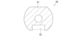
上記実施形態1のノズル30では、ラック33を筒状本体31の下面から突出させた形態としたのに対し、本実施形態2のノズル50は、ラック52を筒状本体51の下面から突出させない形態としている。図6に示すように、筒状本体51の外形(ノズル50の長さ方向と直角な断面形状)は、実施形態1の筒状本体31と概ね同じである。即ち、筒状本体51は、真円において水平な弦を境にして上下対称な一対の弓形部を除去した形状である。そして、この筒状本体51の下面には、ノズル50の長さ方向に複数の台形状の凹部を一定ピッチで形成することによってラック52が形成されている。
In the
また、上記実施形態1では、キャップ40の本体部41が、筒状本体31と同一の形状をなす第1閉塞部41Aと、ラック33と対応する形状の第2閉塞部41Bとから構成されていたのに対し、本実施形態2のキャップ60の本体部61は、筒状本体51と同一の形状をなしており、ラック52と対応する形状の部位は有していない。また、本体部61の外周には、その全周に亘って連続するフランジ部62が形成されている。このフランジ部62と本体部61とは相似形の関係となっている。また、本体部61の後面には、実施形態1と同じ形状の嵌合凸部63が形成されている。
In the first embodiment, the
<他の実施形態>
本発明は上記記述及び図面によって説明した実施形態に限定されるものではなく、例えば次のような実施形態も本発明の技術的範囲に含まれる。
(1)上記実施形態では、キャップが嵌合部に装着され且つノズルが格納位置へ後退したときに、フランジ部の前面における外周縁が、ハウジングの前面に対してほぼ面一状に連なるような形態としたが、これに替えて、フランジ部の外周縁が、ハウジングの前面に対して段差や凹凸等を生じさせる形態で連なるようにしてもよい。
(2)上記実施形態では、キャップが嵌合部に装着され且つノズルが格納位置へ後退したときに、フランジ部の前面とハウジングの前面とが平坦面を形成するようにしたが、これに替えて、フランジ部の前面とハウジングの前面が、曲面を形成するように滑らかに連なる形態としてもよい。
(3)上記実施形態では、キャップの本体部の前面とフランジ部の前面とが面一状に(段差のない平坦面をなすように)連なる形態としたが、本体部の前面とフランジ部の前面とが、段差状に連なるようにしてもよい。
(4)上記実施形態では、キャップの前面をその全領域に亘って平坦面としたが、キャップの前面をその全領域に亘って曲面としてもよく、キャップの前面が平面と曲面で構成されていてもよい。
(5)上記実施形態では、フランジ部の後面における外周縁部と、ハウジングの前面における進退口の開口縁部に、ノズルの進退方向に対して傾斜し且つ互いに密着可能なテーパ面を形成したが、これに替えて、フランジ部の外周縁における後面と、ハウジングの前面における進退口の開口縁部を、ノズルの進退方向に対してほぼ直角な平坦面とし、ノズルが格納位置へ後退したときにフランジ部が進退口の内部に収容されるようにしてよい。
(6)上記実施形態では、ノズル側の嵌合部(嵌合凹部)を、ノズルの前端面における中央部を凹ませた形態としたが、嵌合部は、ノズルの前端面における中央部を突出させた形態としてもよい。
(7)上記実施形態では、ノズル側の嵌合部をノズルの前端面に形成したが、嵌合部は、ノズルの前端部の外周面に形成してもよい。
(8)上記実施形態では、ノズルが格納位置へ後退したときに、ノズルの前端を含む全体が収容室内に収容されるようにしたが、これに替えて、ノズルが格納位置へ後退した状態において、ノズルの前端部が進退口よりも前方に位置するようにしてもよい。この場合、キャップは、帽子形や傘形等のように、フランジ部が本体部よりも後方に位置するような形態とすればよい。
<Other embodiments>
The present invention is not limited to the embodiments described with reference to the above description and drawings. For example, the following embodiments are also included in the technical scope of the present invention.
(1) In the above embodiment, when the cap is mounted on the fitting portion and the nozzle is retracted to the retracted position, the outer peripheral edge of the front surface of the flange portion is substantially flush with the front surface of the housing. However, instead of this, the outer peripheral edge of the flange portion may be continuous with the front surface of the housing in such a way as to cause a step or unevenness.
(2) In the above embodiment, when the cap is attached to the fitting portion and the nozzle is retracted to the storage position, the front surface of the flange portion and the front surface of the housing form a flat surface. Thus, the front surface of the flange portion and the front surface of the housing may be smoothly connected so as to form a curved surface.
(3) In the above-described embodiment, the front surface of the main body portion of the cap and the front surface of the flange portion are connected to be flush with each other (so as to form a flat surface without a step). The front surface may be continuous in steps.
(4) In the above embodiment, the front surface of the cap is a flat surface over the entire region, but the front surface of the cap may be a curved surface over the entire region, and the front surface of the cap is configured with a flat surface and a curved surface. May be.
(5) In the above embodiment, the outer peripheral edge portion on the rear surface of the flange portion and the opening edge portion of the advancement / retraction opening on the front surface of the housing are formed with tapered surfaces that are inclined with respect to the advance / retreat direction of the nozzle and can be in close contact with each other. Instead, when the rear surface on the outer peripheral edge of the flange portion and the opening edge of the advance / retreat port on the front surface of the housing are flat surfaces substantially perpendicular to the advance / retreat direction of the nozzle, the nozzle is retracted to the retracted position. The flange portion may be accommodated inside the advance / retreat port.
(6) In the above-described embodiment, the nozzle-side fitting portion (fitting recess) is in a form in which the central portion of the front end surface of the nozzle is recessed. It is good also as the form made to protrude.
(7) In the above embodiment, the fitting portion on the nozzle side is formed on the front end surface of the nozzle, but the fitting portion may be formed on the outer peripheral surface of the front end portion of the nozzle.
(8) In the above embodiment, when the nozzle is retracted to the storage position, the whole including the front end of the nozzle is accommodated in the accommodation chamber. Instead, in a state where the nozzle is retracted to the storage position. The front end of the nozzle may be positioned in front of the advance / retreat port. In this case, the cap may be configured such that the flange portion is located behind the main body portion, such as a hat shape or an umbrella shape.
10…ハウジング
13…収容室
15…進退口
18…前面側テーパ面(ハウジング側のテーパ面)
30…ノズル
32…吐水口
35…嵌合凹部(嵌合部)
40…キャップ
41…本体部
43…フランジ部
44…後面側テーパ面(ノズル側のテーパ面)
50…ノズル
60…キャップ
DESCRIPTION OF
30 ...
40 ...
50 ...
Claims (3)
洗浄水を吐出する吐水口を有し、少なくとも前記吐水口の形成領域を前記収容室内に収容させる格納位置と、前記吐水口を前記進退口から前記収容室の前方へ進出させる洗浄位置との間での進退を可能に設けられたノズルと、
前記ノズルにおける前記吐水口よりも前方の位置に形成した嵌合部に対し、着脱を可能とされたキャップとを備え、
前記キャップは、
前記キャップが前記嵌合部に装着された状態で前記ノズルの前端面を前方から覆い隠す本体部と、
前記本体部の外周縁に沿って形成され、前記キャップが前記嵌合部に装着され且つ前記ノズルが格納位置へ後退した状態で、前記ノズルの前端外周縁と前記進退口の開口縁との間の隙間を塞ぐフランジ部とを備えて構成されていることを特徴とする局部洗浄装置。 A housing having a storage chamber whose front end is opened as an advancing / retreating port;
Between the storage position which has a water discharge port which discharges cleaning water, and stores at least the formation area of the water discharge port in the storage chamber, and the cleaning position in which the water discharge port advances from the advance / retreat port to the front of the storage chamber A nozzle provided for advancement and retreat in the
A cap made detachable with respect to the fitting portion formed at a position in front of the water discharge port in the nozzle,
The cap is
A main body that covers the front end surface of the nozzle from the front in a state where the cap is mounted on the fitting portion;
Formed along the outer periphery of the main body, the cap is mounted on the fitting portion, and the nozzle is retracted to the retracted position, between the outer periphery of the front end of the nozzle and the opening edge of the advance / retreat port. A local cleaning device comprising a flange portion that closes the gap.
Priority Applications (1)
| Application Number | Priority Date | Filing Date | Title |
|---|---|---|---|
| JP2010269493A JP5653735B2 (en) | 2010-12-02 | 2010-12-02 | Local cleaning equipment |
Applications Claiming Priority (1)
| Application Number | Priority Date | Filing Date | Title |
|---|---|---|---|
| JP2010269493A JP5653735B2 (en) | 2010-12-02 | 2010-12-02 | Local cleaning equipment |
Publications (2)
| Publication Number | Publication Date |
|---|---|
| JP2012117314A true JP2012117314A (en) | 2012-06-21 |
| JP5653735B2 JP5653735B2 (en) | 2015-01-14 |
Family
ID=46500465
Family Applications (1)
| Application Number | Title | Priority Date | Filing Date |
|---|---|---|---|
| JP2010269493A Active JP5653735B2 (en) | 2010-12-02 | 2010-12-02 | Local cleaning equipment |
Country Status (1)
| Country | Link |
|---|---|
| JP (1) | JP5653735B2 (en) |
Citations (2)
| Publication number | Priority date | Publication date | Assignee | Title |
|---|---|---|---|---|
| JPS6193571U (en) * | 1984-11-21 | 1986-06-17 | ||
| JPS6314677U (en) * | 1986-07-15 | 1988-01-30 |
-
2010
- 2010-12-02 JP JP2010269493A patent/JP5653735B2/en active Active
Patent Citations (2)
| Publication number | Priority date | Publication date | Assignee | Title |
|---|---|---|---|---|
| JPS6193571U (en) * | 1984-11-21 | 1986-06-17 | ||
| JPS6314677U (en) * | 1986-07-15 | 1988-01-30 |
Also Published As
| Publication number | Publication date |
|---|---|
| JP5653735B2 (en) | 2015-01-14 |
Similar Documents
| Publication | Publication Date | Title |
|---|---|---|
| JP5429254B2 (en) | Sanitary washing device | |
| JP5782898B2 (en) | Hot water toilet seat | |
| JP5236229B2 (en) | Local cleaning equipment | |
| JP2009041200A5 (en) | ||
| JP2018044365A (en) | Local washing device and toilet bowl including the same | |
| JP2008223244A (en) | Nozzle device and sanitary washing device provided with the same | |
| JP5653735B2 (en) | Local cleaning equipment | |
| JP2010174451A (en) | Flush toilet stool | |
| JP5111769B2 (en) | Sanitary washing toilet seat device and toilet device | |
| JP4218685B2 (en) | Toilet device | |
| JP6762720B2 (en) | Toilet bowl device | |
| JP5605579B2 (en) | Sanitary washing device | |
| JP4940748B2 (en) | Nozzle device and sanitary washing device using it | |
| JP6819209B2 (en) | Toilet seat / lid manufacturing method and toilet seat device | |
| JP4831739B2 (en) | Sanitary washing toilet seat device and toilet device | |
| JP2017125375A (en) | Toilet bowl | |
| JP2008095460A (en) | Western style toilet bowl device | |
| JPH1181420A (en) | Hot water flushing device and toilet seat | |
| JPH09125504A (en) | Western style stool | |
| JP7013935B2 (en) | Local cleaning equipment | |
| JP4836631B2 (en) | Sanitary washing toilet seat device and toilet device | |
| JP5374411B2 (en) | Toilet bowl | |
| JP6649082B2 (en) | Toilet flush tank and toilet flushing device including the same | |
| JP2019138020A (en) | Flush toilet bowl | |
| JP4882599B2 (en) | Local cleaning equipment |
Legal Events
| Date | Code | Title | Description |
|---|---|---|---|
| A621 | Written request for application examination |
Free format text: JAPANESE INTERMEDIATE CODE: A621 Effective date: 20130930 |
|
| A977 | Report on retrieval |
Free format text: JAPANESE INTERMEDIATE CODE: A971007 Effective date: 20140527 |
|
| A131 | Notification of reasons for refusal |
Free format text: JAPANESE INTERMEDIATE CODE: A131 Effective date: 20140603 |
|
| A521 | Written amendment |
Free format text: JAPANESE INTERMEDIATE CODE: A523 Effective date: 20140716 |
|
| TRDD | Decision of grant or rejection written | ||
| A01 | Written decision to grant a patent or to grant a registration (utility model) |
Free format text: JAPANESE INTERMEDIATE CODE: A01 Effective date: 20141118 |
|
| A61 | First payment of annual fees (during grant procedure) |
Free format text: JAPANESE INTERMEDIATE CODE: A61 Effective date: 20141119 |
|
| R150 | Certificate of patent or registration of utility model |
Ref document number: 5653735 Country of ref document: JP Free format text: JAPANESE INTERMEDIATE CODE: R150 |
|
| S111 | Request for change of ownership or part of ownership |
Free format text: JAPANESE INTERMEDIATE CODE: R313111 |
|
| R350 | Written notification of registration of transfer |
Free format text: JAPANESE INTERMEDIATE CODE: R350 |