JP2012125285A - Golf club grip - Google Patents
Golf club grip Download PDFInfo
- Publication number
- JP2012125285A JP2012125285A JP2010276828A JP2010276828A JP2012125285A JP 2012125285 A JP2012125285 A JP 2012125285A JP 2010276828 A JP2010276828 A JP 2010276828A JP 2010276828 A JP2010276828 A JP 2010276828A JP 2012125285 A JP2012125285 A JP 2012125285A
- Authority
- JP
- Japan
- Prior art keywords
- grip
- cylindrical
- cylindrical outer
- ring
- cylindrical inner
- Prior art date
- Legal status (The legal status is an assumption and is not a legal conclusion. Google has not performed a legal analysis and makes no representation as to the accuracy of the status listed.)
- Pending
Links
Images

Landscapes
- Golf Clubs (AREA)
Abstract
【課題】グリップ感と打球方向性の向上を図り、シャフトとの接着力を強固にし、きれいに色分けされたゴルフクラブ用グリップを提供する。
【解決手段】ゴム製の筒状インナー1に、低硬度のゴム製の筒状アウター2を被覆したゴルフクラブ用グリップにおいて、筒状インナーをグリップ全長の半分よりも1〜4cm長く形成し、筒状インナーの軸線方向に基端側から全長の70〜80%の長さ縦突条4を一定間隔で複数本形成し、これら縦突条形成個所の先端側にリング状突起10を形成し、これら縦突条形成個所を被覆し、基端側からリング状突起までの間に形成された第1の筒状アウター2Aの外周面に周溝6を軸線方向で一定間隔で複数本形成し、前記筒状インナーのリング状突起から先端側を被覆し、リング状突起からグリップ先端までを第2の筒状アウター2Bで形成し、この第2の筒状アウターの外周面に複数本の縦溝を形成し、第1と第2の筒状アウターが色違い。
【選択図】図1An object of the present invention is to provide a golf club grip which is improved in grip feeling and hitting direction, has a strong adhesive force with a shaft, and is color-coded clearly.
In a golf club grip in which a rubber tubular inner 1 is coated with a rubber outer tubular member 2 having a low hardness, the tubular inner is formed to be 1 to 4 cm longer than half of the entire length of the grip. A plurality of vertical ridges 4 having a length of 70 to 80% of the total length from the base end side in the axial direction of the inner shape are formed at regular intervals, and a ring-shaped protrusion 10 is formed on the distal end side of these vertical ridge formation portions, Covering these vertical ridge formation locations, forming a plurality of circumferential grooves 6 at regular intervals in the axial direction on the outer peripheral surface of the first cylindrical outer 2A formed between the base end side and the ring-shaped protrusion, The tip end side is covered from the ring-shaped projection of the cylindrical inner, and the ring-shaped projection to the tip of the grip are formed by the second cylindrical outer 2B, and a plurality of vertical grooves are formed on the outer peripheral surface of the second cylindrical outer The first and second cylindrical outer are different colors
[Selection] Figure 1
Description
本発明は、ゴルフクラブ用グリップの構造に関するものである。 The present invention relates to a structure of a golf club grip.
一般にゴルフクラブは、ヘッド、シャフト及びグリップから構成されている。従来のグリップは、例えば天然ゴムを主成分とするゴムにより構成されている。このような材料からグリップが構成されることにより、ゴルファーがゴルフクラブを把持した時のグリップ感覚(握り心地)の向上や、グリップの滑止効果向上並びにグリップの劣化に対する耐性の向上が図られている。 In general, a golf club is composed of a head, a shaft, and a grip. A conventional grip is made of rubber mainly composed of natural rubber, for example. By constructing grips from these materials, it is possible to improve the grip sensation (gripping comfort) when a golfer grips a golf club, improve the grip prevention effect, and improve the resistance to grip deterioration. Yes.
特許文献1(実願昭62−9476号公報)に示すように、シャフトに取付けるグリップを内層部と外層部からなる二層構造として、グリップの全長に亘って内層部を外層部より軟質の材料で構成したり、あるいは特許文献2(実願昭62−82066号公報)に開示されるように、グリップの全長に亘り内層部を外層部より硬質の材料で構成して、握り心地の改善を図ったグリップが知られている。 As shown in Japanese Patent Application Laid-Open No. 62-9476, the grip attached to the shaft has a two-layer structure including an inner layer portion and an outer layer portion, and the inner layer portion is softer than the outer layer portion over the entire length of the grip. Or, as disclosed in Patent Document 2 (Japanese Utility Model Publication No. 62-82066), the inner layer portion is made of a material harder than the outer layer portion over the entire length of the grip, thereby improving grip comfort. The intended grip is known.
一般に、ゴルファーがゴルフクラブのグリップを握る場合、一方の手でグリップの基端側(手元側)を握ってスイング時の軸とし、そして、他方の手をグリップの先端側に添えてこの掌で打球感覚をとらえている。そのため、グリップを軟らかくすると打球感覚があまり伝わらず、一方、グリップを硬くすると手に馴染まず、しかも、強い打球振動がスイングの軸となる手に伝わり過ぎて手首や肘に悪影響を与えてしまうことが指摘されている。 In general, when a golfer grips the grip of a golf club, hold the base of the grip (hand side) with one hand as the axis for swinging, and attach the other hand to the tip of the grip with this palm. It captures the feel of a ball. Therefore, if the grip is soft, the feel of the hit ball is not transmitted well, while if the grip is hard, the hand does not get used to the hand, and the strong hit ball vibration is transmitted to the hand that is the axis of the swing and adversely affects the wrist and elbow. Has been pointed out.
特許文献1に記載のグリップでは、その先端側を握る手で打球感覚を捕らえ難いという欠点があり、特許文献2に開示されたグリップではグリップの基端側を握る手に馴染み難く、しかも、大きな打球振動が肘等に伝わってしまう等の不具合があった。
The grip described in
また、ゴルフクラブのグリップの仕方(握り方)は、ショットの高さ、飛距離、方向をコントロールする上で非常に重要である。そして、グリップの仕方にはヴァードングリップ、インターロック等があり、いずれも一方の手でグリップの基端側を握ってスイングの軸とする場合、その親指をグリップ上に添えてゴルフクラブを安定的に保持し、ゴルフクラブの方向を定めている。 In addition, the way of gripping the golf club (how to grip) is very important in controlling the shot height, flight distance, and direction. And there are various ways to grip, such as Verdon grip, interlock, etc. In either case, when gripping the base end side of the grip with one hand as the axis of swing, attach the thumb on the grip to stabilize the golf club The direction of the golf club.
そして、グリップの先端側に添える手で打球感覚を良好にとらえることができるとともに、握り心地がよくグリップの基端側を握る手の手首や肘等に強い打球振動が伝わらず、しかも、その親指の腹部を支えることによってショットのフックやスライスを積極的に防止したグリップが開発された(特許文献3参照)。これは、内層部と外層部との二層構造からなるゴルフクラブのグリップにおいて、当該グリップの基端側の内層部を外層部よりも軟質の材料で形成するとともに、グリップの先端側の内層部を外層部よりも硬質の材料で形成したものである。 In addition, the hand attached to the tip of the grip provides a good feel for the shot, and it is comfortable to grip and does not transmit strong hitting vibrations to the wrist or elbow of the hand holding the base of the grip. A grip has been developed that actively prevents shot hooking and slicing by supporting the abdomen (see Patent Document 3). In a golf club grip having a two-layer structure of an inner layer portion and an outer layer portion, the inner layer portion on the proximal end side of the grip is formed of a softer material than the outer layer portion, and the inner layer portion on the distal end side of the grip Is formed of a material harder than the outer layer portion.
また、ゴム製グリップではなく、シリコーン樹脂製のグリップとして、特許文献4に記載のものも知られている。このグリップは、ヘッドのフェースとボールの衝突角度のずれを抑えることのできるグリップである。従来、打球方向のずれは専らシャフトのねじりに起因すると考えられていた。しかしながら、シャフトのねじり剛性が向上されても、打球方向がゴルファーの意図する方向からずれてしまうという現象が発生する。この現象の原因を研究するなかで、ゴルフクラブの構成要素であるグリップがシャフトよりも格段に弾性に富むことに着目した。すなわち、上記衝撃力がシャフトのねじり変形を生じさせることは明らかであるものの、ヘッドのフェースとボールとの衝突角度のずれは、上記衝撃力によりグリップが弾性変形することに大きく依存するものであるとの知見を得た結果、特許文献4に記載のグリップが開発された。
Moreover, the thing of
特許文献4の発明は、第1の樹脂からなる筒状インナーと、筒状インナーをインサート部材として当該筒状インナーが被覆されるように第1の樹脂よりも低硬度の第2の樹脂によりインサート成形された筒状アウターとを備えたゴルフクラブ用グリップであり、筒状インナーの外周面に筒状アウターと係合する係合突起が設けられており、係合突起は、周方向に第1のピッチで並設され且つ長手方向に第2のピッチで並設されているものである。
The invention of
特許文献3に記載のグリップは、特許文献1、2に記載のグリップの不都合を解消し、スイングの軸となる手(右利きの人は左手)で握ったグリップの基端側は、軟質材料からなる内層部が変形するためにグリップを確実に握ることができ、かつ握り心地もよく、先端側の手(右手)には、硬質材料で形成された内層部から打球感覚が良好に伝わるようになるが、さらなるグリップ感の向上や打球方向性の向上も望まれていた。
The grip described in
特許文献4に記載のグリップは、ゴム製ではなく、シリコーン樹脂製であり、ゴム製グリップに比べてねじり剛性は向上するが、シャフトに装着すると、装着用溶剤(ホワイトガソリン)がなかなか揮散せず、グリップ装着一週間後にグリップを切断してシャフトとの接触個所を観察したところ、グリップ内周面は濡れた状態であった(溶剤が十分に揮散していない)。すなわち、シャフトとシリコーン樹脂製グリップとの接着力に難があった。
The grip described in
また、外観が多色のグリップも市販されているが、異なる色のゴム製品の接合部で混色したりして色の境目があいまいで、きれいに色分けされたものが見当らず、色の異なるゴムを使用して、明瞭に色分けされたものも、左右の手の役割の明確性を図り、ファッション性を高める上で要望されるに至っている。 In addition, grips with multi-colored appearances are also commercially available, but color boundaries are vague due to color mixing at the joints of rubber products of different colors, and there is no clear color separation, and rubbers of different colors are used. The ones that are clearly color-coded in use have been demanded in order to clarify the roles of the left and right hands and enhance fashionability.
そこで、本発明は、グリップ感と打球方向性の向上を図り、シャフトとの接着力を強固にし、きれいに色分けされたゴルフクラブ用グリップを提供することを目的とする。 SUMMARY OF THE INVENTION Accordingly, an object of the present invention is to provide a golf club grip which is improved in grip feeling and hitting direction, has a strong adhesive force with a shaft, and is color-coded neatly.
上述の目的を達成するため、本発明は、ゴム製の筒状インナーにこの筒状インナーよりも低硬度のゴム製の筒状アウターを被覆した二重構造のゴルフクラブ用グリップにおいて、筒状インナーの長さをグリップ全長の半分の長さよりも1〜4cm長く形成し、筒状インナーの軸線方向に沿って基端側から全長の70〜80%の長さ分の縦突条を外周面にかつ円周方向で一定間隔をあけて複数本形成し、これら縦突条の形成された個所の先端側の円周方向にリング状突起を形成し、これら縦突条形成個所を被覆し、基端側からリング状突起までの間に形成された第1の筒状アウターの外周面に周溝を軸線方向で一定間隔をあけて複数本形成し、前記筒状インナーのリング状突起から先端側を被覆し、リング状突起からグリップ先端までを第2の筒状アウターで形成し、この第2の筒状アウターの外周面に複数本の縦溝を形成し、第1と第2の筒状アウターが色違いであるものである。 In order to achieve the above-mentioned object, the present invention relates to a dual-structure golf club grip in which a rubber cylindrical inner is covered with a rubber cylindrical outer having a lower hardness than that of the cylindrical inner. Is formed to be 1 to 4 cm longer than the half of the overall length of the grip, and the vertical ridge for the length of 70 to 80% of the total length from the base end side along the axial direction of the cylindrical inner is formed on the outer peripheral surface. In addition, a plurality of circumferential protrusions are formed at regular intervals, ring-shaped protrusions are formed in the circumferential direction on the distal end side of the portions where these vertical protrusions are formed, and these vertical protrusion forming portions are covered to form a base. A plurality of circumferential grooves are formed on the outer peripheral surface of the first cylindrical outer formed between the end side and the ring-shaped protrusion at a constant interval in the axial direction, and the ring-shaped protrusion of the cylindrical inner is on the tip side. Cover the second part from the ring-shaped protrusion to the tip of the grip. Formed by Jo outer, this outer peripheral surface of the second cylindrical outer form a longitudinal groove of the plurality of, those first and second tubular outer is a color difference.
本発明によれば、ゴム製の筒状インナーにこの筒状インナーよりも低硬度のゴム製の筒状アウターを被覆した二重構造のゴルフクラブ用グリップにおいて、筒状インナーの長さをグリップ全長の半分の長さよりも1〜4cm長く形成し、筒状インナーの軸線方向に沿って基端側から全長の70〜80%の長さ分の縦突条を外周面にかつ円周方向で一定間隔をあけて複数本形成し、これら縦突条の形成された個所の先端側の円周方向にリング状突起を形成し、これら縦突条形成個所を被覆し、基端側からリング状突起までの間に形成された第1の筒状アウターの外周面に周溝を軸線方向で一定間隔をあけて複数本形成し、前記筒状インナーのリング状突起から先端側を被覆し、リング状突起からグリップ先端までを第2の筒状アウターで形成し、この第2の筒状アウターの外周面に複数本の縦溝を形成し、第1と第2の筒状アウターが色違いであるので、筒状アウターと筒状インナーとの一体化が図れ、かつ縦突条と周溝との組合せにより、グリップ全体のねじれ防止を図ることができ、かつ周溝の存在によりスイング時のヘッドの遠心力に対してグリップ基端側で抵抗することができる。したがって、グリップ基端側(右利きの人は左手で握る部分)の握り心地は、グリップ先端側(右手で握る部分)の握り心地よりも硬くなり、スイング時に軸となる左手で握った部分(基端側)のねじれが少なくなり、打球方向性が向上し、しかも筒状アウターは軟らかいので打球振動の悪影響も出難い。また、筒状インナーはゴム製であり、一般的な装着用溶剤(ホワイトガソリン)と両面接着テープを使用してグリップをシャフトに固着する場合、溶剤が短時間で揮散し、半日程度以下の時間でグリップとシャフトとの固着が強固なものとなる。さらに、筒状インナーのリング状突起の個所で色違いの第1、第2の筒状アウターが被覆形成されているので、色分けが明瞭になされ、ファッション性も向上し、右手と左手との役割分担も強く意識されることとなる。 According to the present invention, in a dual-structure golf club grip in which a rubber cylindrical inner is covered with a rubber cylindrical outer having a hardness lower than that of the cylindrical inner, the length of the cylindrical inner is set to the overall length of the grip. 1 to 4 cm longer than the half of the length, and along the axial direction of the cylindrical inner, 70 to 80% of the total length of the vertical ridge from the base end side is constant on the outer peripheral surface and in the circumferential direction A plurality of lines are formed at intervals, ring-shaped protrusions are formed in the circumferential direction on the distal end side of the portions where the vertical protrusions are formed, and the ring-shaped protrusions are covered from the base end side by covering these vertical protrusion forming portions. A plurality of circumferential grooves are formed at regular intervals in the axial direction on the outer peripheral surface of the first cylindrical outer formed between and the tip side is covered from the ring-shaped protrusion of the cylindrical inner. From the protrusion to the tip of the grip is formed with the second cylindrical outer Since a plurality of vertical grooves are formed on the outer peripheral surface of the second cylindrical outer and the first and second cylindrical outers are different in color, the cylindrical outer and the cylindrical inner can be integrated, In addition, the combination of the vertical ridge and the circumferential groove can prevent the entire grip from being twisted, and the presence of the circumferential groove can resist the centrifugal force of the head during the swing at the grip base end side. Therefore, the grip comfort on the grip base end (the part that the right-handed person grips with the left hand) is harder than the grip comfort on the grip front end (the part gripped with the right hand), and the part gripped with the left hand that becomes the axis during swing ( The twist on the base end side) is reduced, the directionality of the hitting ball is improved, and the cylindrical outer is soft, so that the bad influence of the hitting ball vibration is less likely to occur. In addition, the cylindrical inner is made of rubber, and when the grip is fixed to the shaft using a common mounting solvent (white gasoline) and double-sided adhesive tape, the solvent evaporates in a short time, and the time is about half a day or less. As a result, the grip and the shaft are firmly fixed. In addition, the first and second cylindrical outer rings of different colors are coated at the location of the ring-shaped protrusions of the cylindrical inner, so that the color coding is clear, the fashionability is improved, and the role of the right and left hands Sharing will be strongly conscious.
以下に、本発明の実施形態について図面を参照にして説明する。 Embodiments of the present invention will be described below with reference to the drawings.
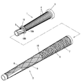
図1では、筒状インナー1と筒状アウター2とを示し、ともにゴム製のものである。最初に筒状インナー1を成形しておき、この筒状インナー1をインサート部材としてモールド内にセットし、筒状インナー1を被覆するように第1と第2の筒状アウター2A、2B(2)を成形する。図1では、別個に成形されたもののように示されているが、説明上の便宜のためであり、筒状アウター2を成形してしまうと、筒状インナー1はリング状突起10を残して筒状アウター2により被覆されてしまうものである。
In FIG. 1, the cylindrical inner 1 and the cylindrical outer 2 are shown, and both are made of rubber. First, the cylindrical inner 1 is formed, the cylindrical inner 1 is set as an insert member in the mold, and the first and second cylindrical outer 2A, 2B (2 ). Although shown in FIG. 1 as being molded separately, for convenience of explanation, if the cylindrical outer 2 is molded, the cylindrical inner 1 leaves the ring-
成形材料としてのゴムは、天然ゴム(NR)を主成分とするものであり、例えば、NR80〜100重量部、SBR(スチレンブタジエンゴム)またはEPDM0〜20重量部、老化防止剤1重量部、ステアリン配1重量部、カーボンブラック10〜30重量部、軟化材5〜10重量部、加工助剤2重量部、亜鉛華5重量部、加硫促進剤1〜2重量部、加硫促進助剤0.5重量部、硫黄1〜2重量部に配合したゴム配合物をグリップ形状に加硫成形する。筒状インナー1と筒状アウター2とでは、ゴム配合物の組成を変え、筒状インナー1を筒状アウター2よりも硬く成形する。そのため、筒状インナー1では、SBRでもスチレン量50%以上のSBRを使用してもよい。筒状アウター2は、ジエン系ゴム45〜90重量部、エチレン−プロピレン二元共重合体及び/又はエチレン−プロピレン−ジエン三元共重合体5〜30重量部、並びに、クロロブチルゴム5〜25重量部を含むゴム配合物を成形、加硫してなるものが好適に使用でき、ジエン系ゴムは天然ゴム、イソプレンゴム、スチレン−ブタジエンゴム、ニトリル−ブタジエンゴム及びクロロプレンゴムよりなる群から選ばれる少なくとも1種であることが好ましい。このようなゴム配合物を用いることにより、動摩擦係数が高く、滑り難く、耐磨耗性および耐候性に優れ、このため耐久性が良好で長寿命となる。さらに、低温特性にも優れ、諸特性の温度安定性が良好であり、べたつきがなく、握ったときのしっとりとした感触は極めて良好なものとなった。また、グリップエンド3は、カーボンブラックに代えてシリカ及びタルク等を補強剤として使用し、顔料を加えて色をつけた。また、硬度を上げるため、スチレン量が50%以上のSBR(ハイスチレンSBR)5〜20重量部の樹脂を加えてもよい。
The rubber as the molding material is mainly composed of natural rubber (NR). For example, NR80 to 100 parts by weight, SBR (styrene butadiene rubber) or EPDM 0 to 20 parts by weight,
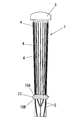
上記筒状インナー1は、図2にも示すように、グリップエンド3側の外周面に長さ8〜11cmの長さを有し、厚み(突起高さ)0.2〜0.6mm、幅0.6〜1.5mmの縦突条4を複数本形成してあり、グリップエンド3側の2本の縦突条4間の間隔を3mmとした。上記グリップエンド3は、筒状インナー1よりも硬いゴム組成物で形成し、筒状インナー1と一体化されている。また、筒状インナー1の先端側(筒状インナー1の全長の4分の1から5分の1の長さを占める)に突条5を形成してある。この突条5の基端と縦突条4の先端の間に円周方向に沿ってリング状突起10を形成してあり、この突起10の両側にも縦突条4や突起10の厚み(突起高さ)よりも厚い肉厚のリング10A、10Bを形成してある。リング状突起10は、リング10A、10Bよりも厚く形成してある。
2, the cylindrical inner 1 has a length of 8 to 11 cm on the outer peripheral surface on the
上記グリップエンド3は、JIS K 6253タイプAの硬度(以下同じJIS基準)が、65〜80であり、筒状インナー1の硬度は、65〜75であり、筒状アウター2の硬度は、35〜55である。このような硬度の値は、限定的なものではなく、物性として筒状アウター2が、筒状インナー1よりも柔らかいものであればよい。
The
上記筒状インナー1の縦突条4を形成した部分、すなわちグリップエンド3とリング状突起10を残した部分を被覆する第1の筒状アウター2Aの部分には、その外周面に周溝6を複数本形成してある。これら周溝6は、溝幅が0.1〜0.3mmほどの細い溝であり、軸線方向において1.5mmほどの間隔で並設してある。これら周溝6をクロスするように斜めの溝7も多数形成してある。これらの溝6、7により滑り止めが図られているが、周溝6は、スイング時におけるヘッド遠心力に対してグリップ部分で対抗する力が働き易くするためのものでもある。また、筒状インナー1のリング状突起10よりも先端側に形成される第2の筒状アウター2Bの外周面には、複数本の縦溝8を形成するとともに、これら縦溝8をクロスするように斜めの溝9も多数形成してある。リング状突起10で区分されたこれら第1と第2の筒状アウター2A、2Bとは、互いに色違いのゴムを使用する。
The portion of the tubular inner 1 where the
上記筒状インナー1の全長は、グリップ全長(グリップエンド3を含めた全長)の半分よりも1〜4cm長く形成してある。全長の半分よりも4cmを超える長さの筒状インナー1だと、グリップ全重量が増えてしまう。筒状インナー1を必要以上に長くしても、グリップとしての機能の向上は見られない。 The total length of the cylindrical inner 1 is formed to be 1 to 4 cm longer than half of the total grip length (the total length including the grip end 3). If the cylindrical inner 1 has a length exceeding 4 cm rather than half of the total length, the total weight of the grip increases. Even if the cylindrical inner 1 is made longer than necessary, the function as a grip is not improved.
上記リング状突起10の個所で明瞭に色分けされた第1の筒状アウター2Aと第2の筒状アウター2Bとでは、ゴムの硬さを変えて成形することができる。第1の筒状アウター2A(基端側)よりも第2の筒状アウター2B(先端側)を硬くするのが好ましい。第2の筒状アウター2Bは、薄肉であるため硬度を45〜55、第1の筒状アウター2Aは、筒状インナー1の縦突条4を感じるほどの柔らかさ(35〜45)であることが好ましい。
The first cylindrical outer 2 </ b> A and the second cylindrical outer 2 </ b> B that are clearly color-coded at the location of the ring-shaped
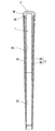
グリップエンド3には、図3に示すように嵌合部3Aとフランジ部3Bが形成され、嵌合部3Aが筒状インナー1の後端に嵌合し、固着されている。上記フランジ部3Bの外径は、筒状アウター2の基端側外径と同一に形成されている。筒状インナー1の内壁1Aで囲まれた中空部と第2の筒状アウター2Bの内壁2Cで囲まれた中空部には、図示しないシャフトが挿入され、シャフトにグリップが装着される。シャフトとグリップとの固着は、シャフトに両面接着テープを貼り付け、このテープとシャフト内壁面に装着用溶剤を塗布し、シャフトをすばやくグリップの中空部に差し込む。10時間経過後にグリップを切り開いたところ、グリップ内壁面もテープも乾燥状態にあった。
As shown in FIG. 3, the
上記筒状インナー1と筒状アウター2のそれぞれの肉厚は、少なくとも筒状インナー1を被覆する部分の筒状アウター2の肉厚よりも筒状インナー1の肉厚の方が厚く形成されている。ゴルファーがボールを打ったときの衝撃力は、グリップにねじり変形を与えるが、柔らかい筒状アウター2の変形に大きく依存している。しかしながら、硬く肉厚の厚い筒状インナー1が、柔らかく肉厚の薄い筒状アウター2で被覆されているので、グリップとしての全体のねじり剛性は向上する。また、筒状インナー1に形成された縦突条4もグリップのねじり剛性の向上に寄与している。ねじり剛性が向上すれば、打球方向性も向上する。
The thickness of each of the cylindrical inner 1 and the cylindrical outer 2 is such that the thickness of the cylindrical inner 1 is thicker than the thickness of the cylindrical outer 2 at least covering the
上記グリップエンド3は、筒状インナー1の本体部分(グリップエンド3を除く部分)とは色違いであり、色違いの材料を加硫成形するので、図1や図2に示すように、その境目が波打つようになり、はっきりと色分けされにくくなっている。
The
前記第1筒状アウター2Aと第2筒状アウター2Bの色違いの成形は、最初に射出成形により筒状インナー1を成形し、このとき筒状インナー1に中空部を成形するためマンドレル11の周囲に材料が射出され、成形後もこのマンドレル11を抜き取らず、マンドレル11付きの筒状インナー1を上金型12と下金型13で囲まれた空間にインサートする。そして、図4に示すように、リング状突起10からグリップ基端側とグリップ先端側とでは、色違いのゴムシート14、15を筒状インナー1に巻き付ける。上下金型12、13を締結し、ゴムシート14、15をコンプレッション成形し、ゴムシート14が第1の筒状アウター2Aとなり、ゴムシート15が第2の筒状アウター2Bとなる。
The different shapes of the first cylindrical outer 2A and the second cylindrical outer 2B are formed by first forming the cylindrical inner 1 by injection molding. At this time, the hollow portion is formed in the cylindrical inner 1 so that the
1 筒状インナー
2 筒状アウター
2A 第1の筒状アウター
2B 第2の筒状アウター
4 縦突条
6 周溝
8 縦溝
10 リング状突起
DESCRIPTION OF
Claims (3)
筒状インナーの長さをグリップ全長の半分の長さよりも1〜4cm長く形成し、
筒状インナーの軸線方向に沿って基端側から全長の70〜80%の長さ分の縦突条を外周面にかつ円周方向で一定間隔をあけて複数本形成し、
これら縦突条の形成された個所の先端側の円周方向にリング状突起を形成し、
これら縦突条形成個所を被覆し、基端側からリング状突起までの間に形成された第1の筒状アウターの外周面に周溝を軸線方向で一定間隔をあけて複数本形成し、
前記筒状インナーのリング状突起から先端側を被覆し、リング状突起からグリップ先端までを第2の筒状アウターで形成し、
この第2の筒状アウターの外周面に複数本の縦溝を形成し、
第1と第2の筒状アウターが色違いであることを特徴とするゴルフクラブ用グリップ。 In a golf club grip having a double structure in which a rubber cylindrical inner is coated with a rubber cylindrical outer having a lower hardness than that of the cylindrical inner,
The length of the cylindrical inner is 1 to 4 cm longer than half the length of the grip,
A plurality of vertical ridges having a length of 70 to 80% of the total length from the base end side along the axial direction of the cylindrical inner are formed on the outer peripheral surface and at regular intervals in the circumferential direction,
Forming a ring-shaped protrusion in the circumferential direction on the tip side of the portion where these vertical protrusions are formed,
Covering these vertical ridge formation locations, forming a plurality of circumferential grooves at regular intervals in the axial direction on the outer peripheral surface of the first cylindrical outer formed from the base end side to the ring-shaped protrusion,
Covering the tip side from the ring-shaped projection of the cylindrical inner, forming the ring-shaped projection to the grip tip with a second cylindrical outer,
A plurality of longitudinal grooves are formed on the outer peripheral surface of the second cylindrical outer,
A golf club grip, wherein the first and second cylindrical outers are different in color.
The golf club grip according to claim 1 or 2, wherein the second cylindrical outer constituting the cylindrical outer is harder than the hardness of the first cylindrical outer.
Priority Applications (3)
| Application Number | Priority Date | Filing Date | Title |
|---|---|---|---|
| JP2010276828A JP2012125285A (en) | 2010-12-13 | 2010-12-13 | Golf club grip |
| CN2011102398715A CN102475958A (en) | 2010-11-22 | 2011-08-19 | Golf club grip |
| US13/240,737 US20120129624A1 (en) | 2010-11-22 | 2011-09-22 | Golf club grip |
Applications Claiming Priority (1)
| Application Number | Priority Date | Filing Date | Title |
|---|---|---|---|
| JP2010276828A JP2012125285A (en) | 2010-12-13 | 2010-12-13 | Golf club grip |
Publications (1)
| Publication Number | Publication Date |
|---|---|
| JP2012125285A true JP2012125285A (en) | 2012-07-05 |
Family
ID=46643067
Family Applications (1)
| Application Number | Title | Priority Date | Filing Date |
|---|---|---|---|
| JP2010276828A Pending JP2012125285A (en) | 2010-11-22 | 2010-12-13 | Golf club grip |
Country Status (1)
| Country | Link |
|---|---|
| JP (1) | JP2012125285A (en) |
Cited By (2)
| Publication number | Priority date | Publication date | Assignee | Title |
|---|---|---|---|---|
| KR102596851B1 (en) * | 2022-05-09 | 2023-10-31 | 김훤 | Grip for golf club |
| KR20240149296A (en) * | 2023-04-05 | 2024-10-14 | 김찬석 | Multi Layer or Flex Golf Grip and Manufacturing Method thereof |
-
2010
- 2010-12-13 JP JP2010276828A patent/JP2012125285A/en active Pending
Cited By (3)
| Publication number | Priority date | Publication date | Assignee | Title |
|---|---|---|---|---|
| KR102596851B1 (en) * | 2022-05-09 | 2023-10-31 | 김훤 | Grip for golf club |
| KR20240149296A (en) * | 2023-04-05 | 2024-10-14 | 김찬석 | Multi Layer or Flex Golf Grip and Manufacturing Method thereof |
| KR102823217B1 (en) * | 2023-04-05 | 2025-06-25 | 김찬석 | Multi Layer or Flex Golf Grip |
Similar Documents
| Publication | Publication Date | Title |
|---|---|---|
| JP2596956Y2 (en) | Golf club grip | |
| US5634859A (en) | Grip with increased soft feel and tackiness with decreased torque | |
| US7691016B2 (en) | Racket | |
| JP5939745B2 (en) | Replaceable handle with grip | |
| CN102475958A (en) | Golf club grip | |
| US7201683B2 (en) | Elastic grip handle for a baseball/softball bat | |
| JPS6121426B2 (en) | ||
| US20200384322A1 (en) | Composite golf club grip with foam layer | |
| US11154757B2 (en) | Grip for golf club | |
| WO2005011819A1 (en) | Golf ball and molding die molding the core of the golf ball | |
| JP2012125285A (en) | Golf club grip | |
| JP2012110404A (en) | Golf club grip | |
| JP2011030938A (en) | Grip for golf club | |
| JP2019000659A (en) | Golf club | |
| KR20080112484A (en) | Golf club grip | |
| JP2003117035A (en) | Golf club grip | |
| JP3701220B2 (en) | Anti-slip member, golf club grip and golf club | |
| JP5823157B2 (en) | Golf club grip | |
| KR20150000388U (en) | Handgrip of golf club | |
| US7980962B2 (en) | Golf club and grip for golf club | |
| JPH0411737Y2 (en) | ||
| JPH08308970A (en) | Grip for ball hitting tool, ball hitting tool and golf club | |
| JP6498344B1 (en) | Golf club grip and golf club | |
| JP2012223482A (en) | Golf club grip | |
| JP2857344B2 (en) | Golf club grip |