JP2012127198A - Compressor - Google Patents
Compressor Download PDFInfo
- Publication number
- JP2012127198A JP2012127198A JP2010276691A JP2010276691A JP2012127198A JP 2012127198 A JP2012127198 A JP 2012127198A JP 2010276691 A JP2010276691 A JP 2010276691A JP 2010276691 A JP2010276691 A JP 2010276691A JP 2012127198 A JP2012127198 A JP 2012127198A
- Authority
- JP
- Japan
- Prior art keywords
- piston
- pressure chamber
- drive shaft
- blade
- eccentric
- Prior art date
- Legal status (The legal status is an assumption and is not a legal conclusion. Google has not performed a legal analysis and makes no representation as to the accuracy of the status listed.)
- Withdrawn
Links
Images



Landscapes
- Applications Or Details Of Rotary Compressors (AREA)
Abstract
Description
本発明は、圧縮機に関するものである。 The present invention relates to a compressor.
従来より、ピストンをシリンダ内で偏心回転させることによって冷媒を圧縮するロータリ型の圧縮機が知られている。この種の圧縮機の中には、シリンダを複数備えたものが知られている(例えば、特許文献1,2参照)。ここで、駆動軸の摺動損失を低減して効率を向上するためには、駆動軸の摺動部分で最も軸径の大きい偏心部の直径を小径化するとともに、偏心部の偏心量を大きくすることが好ましい。 Conventionally, a rotary type compressor that compresses a refrigerant by rotating a piston eccentrically in a cylinder is known. Some compressors of this type are provided with a plurality of cylinders (for example, see Patent Documents 1 and 2). Here, in order to improve the efficiency by reducing the sliding loss of the drive shaft, the diameter of the eccentric portion having the largest shaft diameter in the sliding portion of the drive shaft is reduced and the eccentric amount of the eccentric portion is increased. It is preferable to do.
そこで、特許文献1,2では、駆動軸の主軸部の外周面に対して偏心部の外周面を窪ませるとともに、副軸部の直径を主軸部の直径よりも小さくしている。ところで、このような形状の駆動軸において、偏心部間の距離がピストンの軸方向の長さよりも短い場合には、副軸部側から偏心部にピストンを挿通させて組み付けようとしても、下側の偏心部を通過したピストンが上側の偏心部に当接して進まず、上側の偏心部に嵌め込むことができないという問題がある。 Therefore, in Patent Documents 1 and 2, the outer peripheral surface of the eccentric portion is recessed with respect to the outer peripheral surface of the main shaft portion of the drive shaft, and the diameter of the auxiliary shaft portion is made smaller than the diameter of the main shaft portion. By the way, in the drive shaft having such a shape, when the distance between the eccentric portions is shorter than the length in the axial direction of the piston, even if the piston is inserted from the auxiliary shaft portion to the eccentric portion, There is a problem that the piston that has passed through the eccentric part does not advance in contact with the upper eccentric part and cannot be fitted into the upper eccentric part.
これに対し、特許文献1では、偏心部間の距離がピストンの軸方向の長さよりも長くなるように駆動軸を形成している。また、特許文献2では、ピストンを軸方向に2つに分割することで、分割したピストンが偏心部間を通過できるようにしている。 On the other hand, in Patent Document 1, the drive shaft is formed such that the distance between the eccentric portions is longer than the axial length of the piston. In Patent Document 2, the piston is divided into two in the axial direction so that the divided piston can pass between the eccentric portions.
しかしながら、特許文献1のように、偏心部間の距離を長くすると、主軸部と副軸部とをそれぞれ軸受する主軸受と副軸受との間の距離(軸受間距離)が長くなるため、駆動軸の撓みが大きくなり、軸受にかかる面圧が増加して信頼性が低下する。また、特許文献2のように、ピストンを軸方向に分割すると、軸受の隙間管理が難しくなって油膜が発生しにくくなるという問題がある。 However, as in Patent Document 1, when the distance between the eccentric parts is increased, the distance between the main bearing and the auxiliary bearing that respectively bears the main shaft part and the sub shaft part (inter-bearing distance) increases. The deflection of the shaft increases, the surface pressure applied to the bearing increases, and the reliability decreases. Further, as in Patent Document 2, when the piston is divided in the axial direction, there is a problem that it becomes difficult to manage the bearing clearance and an oil film is hardly generated.
また、特許文献1,2では、副軸部側から偏心部にピストンを挿通させるべく副軸部の直径を小さくしているので、駆動軸の剛性を確保する上で不利になるという問題がある。なお、このような問題は、シリンダを1つのみ備えた単気筒型の圧縮機であっても同様に生じるものである。すなわち、駆動軸の主軸部の外周面に対して偏心部の外周面を窪ませた場合には、ピストンを挿通させるために副軸部の直径を主軸部の直径よりも小さくする必要があり、駆動軸の剛性を確保する上で不利になる。 Moreover, in patent document 1, 2, since the diameter of a subshaft part is made small so that a piston may be inserted in an eccentric part from the subshaft part side, there exists a problem that it becomes disadvantageous when ensuring the rigidity of a drive shaft. . Such a problem occurs similarly even in a single-cylinder compressor having only one cylinder. That is, when the outer peripheral surface of the eccentric portion is recessed relative to the outer peripheral surface of the main shaft portion of the drive shaft, it is necessary to make the diameter of the auxiliary shaft portion smaller than the diameter of the main shaft portion in order to insert the piston, This is disadvantageous in ensuring the rigidity of the drive shaft.
本発明は、かかる点に鑑みてなされたものであり、その目的は、駆動軸の撓みを抑制するとともにピストンの組付性の向上を図ることにある。 The present invention has been made in view of such points, and an object thereof is to suppress the bending of the drive shaft and to improve the assembling property of the piston.
本発明は、主軸部(33a)と該主軸部(33a)の回転中心から偏心した偏心部(33c)とを有する駆動軸(33)と、該駆動軸(33)の偏心部(33c)に嵌合されるリング状のピストン(21)と、該ピストン(21)を収容するシリンダ室(S)を有するシリンダ(25)とを備えた圧縮機を対象とし、次のような解決手段を講じた。 The present invention provides a drive shaft (33) having a main shaft portion (33a) and an eccentric portion (33c) eccentric from the rotation center of the main shaft portion (33a), and an eccentric portion (33c) of the drive shaft (33). The following solution is taken for a compressor including a ring-shaped piston (21) to be fitted and a cylinder (25) having a cylinder chamber (S) for accommodating the piston (21). It was.
すなわち、第1の発明は、前記駆動軸(33)は、前記主軸部(33a)の半径Rm、前記偏心部(33c)の半径Rc、該主軸部(33a)の回転中心に対する該偏心部(33c)の偏心量eが、Rc<(Rm+e)という条件を満たすように構成され、
前記ピストン(21)には、軸方向から見て前記主軸部(33a)と重なり合わないように内周面の一部が窪んだ凹部(22a)が形成されていることを特徴とするものである。
That is, in the first invention, the drive shaft (33) includes the radius Rm of the main shaft portion (33a), the radius Rc of the eccentric portion (33c), and the eccentric portion with respect to the rotation center of the main shaft portion (33a) ( 33c) is configured such that the eccentricity e satisfies the condition Rc <(Rm + e),
The piston (21) has a recess (22a) in which a part of the inner peripheral surface is recessed so as not to overlap with the main shaft portion (33a) when viewed from the axial direction. is there.
第1の発明では、駆動軸(33)は、上述した条件式を満たすように構成される。ピストン(21)の内周面の一部は窪んでおり、軸方向から見て主軸部(33a)と重なり合わないような凹部(22a)が形成される。 In the first invention, the drive shaft (33) is configured to satisfy the conditional expression described above. A part of the inner peripheral surface of the piston (21) is recessed, and a recess (22a) is formed so as not to overlap the main shaft (33a) when viewed from the axial direction.
このような構成とすれば、駆動軸(33)の軸方向からピストン(21)を挿通させる際に、ピストン(21)が主軸部(33a)と干渉することなく偏心部(33c)に嵌め込むことができる。また、従来のように偏心部(33c)の偏心量に応じて主軸部(33a)の軸径を小さくしなくても偏心部(33c)に対してピストン(21)を嵌め込むことができるので、駆動軸(33)の剛性を確保することができる。これにより、駆動軸(33)の撓みを抑制しつつピストン(21)の組付性の向上を図ることができる。 With this configuration, when the piston (21) is inserted from the axial direction of the drive shaft (33), the piston (21) is fitted into the eccentric portion (33c) without interfering with the main shaft portion (33a). be able to. Further, the piston (21) can be fitted into the eccentric part (33c) without reducing the shaft diameter of the main shaft part (33a) according to the eccentric amount of the eccentric part (33c) as in the prior art. The rigidity of the drive shaft (33) can be ensured. Thereby, the assembly | attachment property of a piston (21) can be aimed at, suppressing the bending of a drive shaft (33).
第2の発明は、第1の発明において、
前記シリンダ室(S)内を低圧室(L)と高圧室(H)とに区画するブレード(24)を備え、
前記ピストン(21)の凹部(22a)は、前記ブレード(24)と該ピストン(21)との境界位置から前記低圧室(L)側に向かう該ピストン(21)半周分の範囲内に配置されていることを特徴とするものである。
According to a second invention, in the first invention,
A blade (24) that divides the inside of the cylinder chamber (S) into a low pressure chamber (L) and a high pressure chamber (H);
The recess (22a) of the piston (21) is arranged within a range of a half circumference of the piston (21) from the boundary position between the blade (24) and the piston (21) toward the low pressure chamber (L). It is characterized by that.
第2の発明では、ブレード(24)によってシリンダ室(S)内が低圧室(L)と高圧室(H)とに区画される。そして、ピストン(21)の凹部(22a)は、ブレード(24)とピストン(21)との境界位置から低圧室(L)側に向かうピストン(21)半周分の範囲内に配置される。 In the second invention, the inside of the cylinder chamber (S) is divided into a low pressure chamber (L) and a high pressure chamber (H) by the blade (24). And the recessed part (22a) of a piston (21) is arrange | positioned in the range for the piston (21) half circumference which goes to a low pressure chamber (L) side from the boundary position of a braid | blade (24) and piston (21).
このような構成とすれば、ブレード(24)とピストン(21)との境界位置から低圧室(L)側に向かうピストン(21)半周分の範囲内では、その反対側の範囲に比べて冷媒による圧力負荷が小さいため、ピストン(21)の凹部(22a)を高圧室(H)側に配置する場合に比べてピストン(21)の凹部(22a)に加わる応力を低減することができる。 In such a configuration, the refrigerant in the range of the half circumference of the piston (21) heading from the boundary position between the blade (24) and the piston (21) toward the low pressure chamber (L) side is larger than the range on the opposite side. Therefore, the stress applied to the recess (22a) of the piston (21) can be reduced as compared with the case where the recess (22a) of the piston (21) is arranged on the high pressure chamber (H) side.
第3の発明は、第1又は第2の発明において、
前記凹部(22a)と前記偏心部(33c)との間に嵌合される嵌合部材(23)を備えたことを特徴とするものである。
According to a third invention, in the first or second invention,
A fitting member (23) fitted between the concave portion (22a) and the eccentric portion (33c) is provided.
第3の発明では、凹部(22a)と偏心部(33c)との間に嵌合部材(23)が嵌合される。このような構成とすれば、嵌合部材(23)によってピストン(21)の剛性を高めることができる。 In the third invention, the fitting member (23) is fitted between the recess (22a) and the eccentric part (33c). With such a configuration, the rigidity of the piston (21) can be increased by the fitting member (23).
第4の発明は、第1乃至第3の発明のうち何れか1つにおいて、
前記ピストン(21)に一体形成され、前記シリンダ室(S)内を低圧室(L)と高圧室(H)とに区画するブレード(24)を備え、
前記ピストン(21)は、前記シリンダ室(S)内で揺動自在な揺動型の圧縮機構(20)を構成していることを特徴とするものである。
According to a fourth invention, in any one of the first to third inventions,
A blade (24) that is integrally formed with the piston (21) and divides the cylinder chamber (S) into a low pressure chamber (L) and a high pressure chamber (H);
The piston (21) constitutes an oscillating compression mechanism (20) that can oscillate in the cylinder chamber (S).
第4の発明では、ピストン(21)にはブレード(24)が一体形成される。ブレード(24)によってシリンダ室(S)内が低圧室(L)と高圧室(H)とに区画される。また、ピストン(21)は、シリンダ室(S)内で揺動自在な揺動型の圧縮機構(20)を構成している。 In the fourth invention, the blade (24) is integrally formed with the piston (21). The cylinder (S) is partitioned into a low pressure chamber (L) and a high pressure chamber (H) by the blade (24). The piston (21) constitutes a swinging compression mechanism (20) that can swing within the cylinder chamber (S).
このような構成とすれば、駆動軸(33)の回転に伴うピストン(21)の自転をブレード(24)によって防止して、揺動型の圧縮機構(20)を実現することができる。 With such a configuration, the rotation of the piston (21) accompanying the rotation of the drive shaft (33) can be prevented by the blade (24), and the swing type compression mechanism (20) can be realized.
第5の発明は、第1乃至第3の発明のうち何れか1つにおいて、
前記ピストン(21)に摺接するように配置され、前記シリンダ室(S)内を低圧室(L)と高圧室(H)とに区画するブレード(24)と、
前記駆動軸(33)の回転に伴う前記ピストン(21)の自転を防止する自転防止機構(50)とを備え、
前記ピストン(21)は、前記シリンダ室(S)内で回転自在なロータリ型の圧縮機構(20)を構成していることを特徴とするものである。
According to a fifth invention, in any one of the first to third inventions,
A blade (24) disposed so as to be in sliding contact with the piston (21) and dividing the inside of the cylinder chamber (S) into a low pressure chamber (L) and a high pressure chamber (H);
A rotation prevention mechanism (50) for preventing rotation of the piston (21) accompanying rotation of the drive shaft (33);
The piston (21) constitutes a rotary compression mechanism (20) that is rotatable in the cylinder chamber (S).
第5の発明では、ブレード(24)によってシリンダ室(S)内が低圧室(L)と高圧室(H)とに区画される。ブレード(24)は、ピストン(21)に摺接するように配置される。駆動軸(33)の回転に伴うピストン(21)の自転は、自転防止機構(50)によって防止される。また、ピストン(21)は、シリンダ室(S)内で回転自在なロータリ型の圧縮機構(20)を構成している。 In the fifth invention, the inside of the cylinder chamber (S) is divided into a low pressure chamber (L) and a high pressure chamber (H) by the blade (24). The blade (24) is disposed so as to be in sliding contact with the piston (21). The rotation of the piston (21) accompanying the rotation of the drive shaft (33) is prevented by the rotation prevention mechanism (50). The piston (21) constitutes a rotary compression mechanism (20) that is rotatable in the cylinder chamber (S).
このような構成とすれば、駆動軸(33)の回転に伴うピストン(21)の自転を自転防止機構(50)によって防止して、ロータリ型の圧縮機構(20)を実現することができる。 With such a configuration, the rotation of the piston (21) accompanying the rotation of the drive shaft (33) can be prevented by the rotation prevention mechanism (50), and the rotary compression mechanism (20) can be realized.
本発明によれば、駆動軸(33)の軸方向からピストン(21)を挿通させる際に、ピストン(21)が主軸部(33a)と干渉することなく偏心部(33c)に嵌め込むことができる。また、従来のように偏心部(33c)の偏心量に応じて主軸部(33a)の軸径を小さくしなくても偏心部(33c)に対してピストン(21)を嵌め込むことができるので、駆動軸(33)の剛性を確保することができる。これにより、駆動軸(33)の撓みを抑制しつつピストン(21)の組付性の向上を図ることができる。 According to the present invention, when the piston (21) is inserted from the axial direction of the drive shaft (33), the piston (21) can be fitted into the eccentric portion (33c) without interfering with the main shaft portion (33a). it can. Further, the piston (21) can be fitted into the eccentric part (33c) without reducing the shaft diameter of the main shaft part (33a) according to the eccentric amount of the eccentric part (33c) as in the prior art. The rigidity of the drive shaft (33) can be ensured. Thereby, the assembly | attachment property of a piston (21) can be aimed at, suppressing the bending of a drive shaft (33).
以下、本発明の実施形態を図面に基づいて説明する。なお、以下の好ましい実施形態の説明は、本質的に例示に過ぎず、本発明、その適用物或いはその用途を制限することを意図するものではない。 Hereinafter, embodiments of the present invention will be described with reference to the drawings. It should be noted that the following description of the preferred embodiment is merely illustrative in nature and is not intended to limit the present invention, its application, or its use.
《実施形態1》
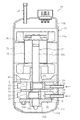
図1は、本発明の実施形態1に係る圧縮機の縦断面図である。この圧縮機(10)は、縦長で円筒形の密閉容器であるケーシング(11)を備えている。ケーシング(11)内には、図1における下寄りの位置に2つの圧縮機構(20)が上下方向に並んで配置され、上寄りの位置に電動機(30)が配置されている。この圧縮機(10)は、冷媒(例えば二酸化炭素)が充填されて蒸気圧縮冷凍サイクルを行う冷凍装置の冷媒回路に設けられる。
Embodiment 1
FIG. 1 is a longitudinal sectional view of a compressor according to Embodiment 1 of the present invention. The compressor (10) includes a casing (11) which is a vertically long and cylindrical sealed container. In the casing (11), two compression mechanisms (20) are arranged in the vertical direction at the lower position in FIG. 1, and the electric motor (30) is arranged at the upper position. The compressor (10) is provided in a refrigerant circuit of a refrigerating apparatus that is filled with a refrigerant (for example, carbon dioxide) and performs a vapor compression refrigeration cycle.
ケーシング(11)は、円筒形状の胴部(11a)と、胴部(11a)の上端及び下端にそれぞれ固定された椀状の上部鏡板(11b)及び下部鏡板(11c)とを備えている。 The casing (11) includes a cylindrical body portion (11a), and a bowl-shaped upper end plate (11b) and lower end plate (11c) fixed to the upper end and the lower end of the body portion (11a), respectively.
ケーシング(11)の胴部(11a)には、2つの吸入管(12)が貫通するように設けられている。2つの吸入管(12)は、2つの圧縮機構(20)にそれぞれ接続されている。また、ケーシング(11)の上部鏡板(11b)には、吐出管(13)が貫通するように設けられている。吐出管(13)は、ケーシング(11)の内部空間であって電動機(30)の上方において開口している。また、ケーシング(11)内の下部には、圧縮機構(20)等の各摺動部に供給される潤滑油が貯留される油溜まり(11d)が形成されている。 Two suction pipes (12) are provided through the body (11a) of the casing (11). The two suction pipes (12) are connected to the two compression mechanisms (20), respectively. The upper end plate (11b) of the casing (11) is provided with a discharge pipe (13) passing therethrough. The discharge pipe (13) is an internal space of the casing (11) and opens above the electric motor (30). An oil sump (11d) is formed in the lower part of the casing (11) for storing lubricating oil supplied to each sliding portion such as the compression mechanism (20).
電動機(30)は、ステータ(31)とロータ(32)とを備えている。ステータ(31)は、ケーシング(11)の胴部(11a)の内壁に固定されている。また、ロータ(32)は、ステータ(31)の内側に配置され、ケーシング(11)の内部を上下方向に延びる駆動軸(33)と連結されている。このような構成により、駆動軸(33)は、ロータ(32)の回転に伴って回転する。 The electric motor (30) includes a stator (31) and a rotor (32). The stator (31) is fixed to the inner wall of the body (11a) of the casing (11). The rotor (32) is disposed inside the stator (31) and is coupled to a drive shaft (33) extending in the vertical direction inside the casing (11). With such a configuration, the drive shaft (33) rotates as the rotor (32) rotates.
駆動軸(33)は、上端側の主軸部(33a)と、下端側の副軸部(33b)と、主軸部(33a)と副軸部(33b)との間に設けられた2つの偏心部(33c)と、2つの偏心部(33c)同士を連結する中間軸部(33d)とを備えている。 The drive shaft (33) has two eccentric portions provided between the main shaft portion (33a) on the upper end side, the sub shaft portion (33b) on the lower end side, and the main shaft portion (33a) and the sub shaft portion (33b). A portion (33c) and an intermediate shaft portion (33d) for connecting the two eccentric portions (33c) to each other are provided.
主軸部(33a)の上部には、電動機(30)が連結されている。また、主軸部(33a)の下部は、ケーシング(11)の胴部(11a)に固定された主軸受(41)によって回転自在に支持されている。一方、副軸部(33b)は、ケーシング(11)の胴部(11a)に固定された副軸受(42)によって回転自在に支持されている。中間軸部(33d)には、ミドルプレート(43)が連結されている。 An electric motor (30) is coupled to the upper portion of the main shaft portion (33a). The lower portion of the main shaft portion (33a) is rotatably supported by a main bearing (41) fixed to the body portion (11a) of the casing (11). On the other hand, the auxiliary shaft part (33b) is rotatably supported by an auxiliary bearing (42) fixed to the body part (11a) of the casing (11). A middle plate (43) is connected to the intermediate shaft portion (33d).
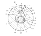
偏心部(33c)は、主軸部(33a)及び副軸部(33b)よりも大径の円柱形状となるように形成されている。2つの偏心部(33c)の偏心方向は、位相が180°ずれるように形成されている。そして、図2に示すように、駆動軸(33)は、主軸部(33a)の半径Rm、偏心部(33c)の半径Rc、主軸部(33a)の回転中心に対する偏心部(33c)の偏心量eが、Rc<(Rm+e)という条件を満たすように構成されている。なお、偏心量eは、e>4[mm]とするのが好ましい。 The eccentric part (33c) is formed in a cylindrical shape having a larger diameter than the main shaft part (33a) and the sub shaft part (33b). The eccentric directions of the two eccentric portions (33c) are formed so that the phases are shifted by 180 °. As shown in FIG. 2, the drive shaft (33) has a radius Rm of the main shaft portion (33a), a radius Rc of the eccentric portion (33c), and an eccentricity of the eccentric portion (33c) with respect to the rotation center of the main shaft portion (33a). The quantity e is configured to satisfy the condition of Rc <(Rm + e). The eccentricity e is preferably e> 4 [mm].
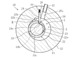
図3は、圧縮機構を拡大して示す図である。図3に示すように、圧縮機構(20)は、シリンダ室(S)を有するシリンダ(25)と、シリンダ室(S)内に収容されるピストン(21)と、シリンダ室(S)を低圧室(L)と高圧室(H)とに仕切るブレード(24)とを備えている。ここで、シリンダ(25)は、シリンダ室(S)の内径D、シリンダ室(S)の高さhが、D/h>3という条件を満たすような偏平シリンダとするのが好ましい。 FIG. 3 is an enlarged view of the compression mechanism. As shown in FIG. 3, the compression mechanism (20) includes a cylinder (25) having a cylinder chamber (S), a piston (21) accommodated in the cylinder chamber (S), and a low pressure in the cylinder chamber (S). A blade (24) is provided to partition the chamber (L) and the high pressure chamber (H). Here, the cylinder (25) is preferably a flat cylinder in which the inner diameter D of the cylinder chamber (S) and the height h of the cylinder chamber (S) satisfy the condition of D / h> 3.
シリンダ(25)は、ドーナツ板状に形成され、中央の孔にはピストン(21)が収容されている。また、シリンダ(25)には、吸入ポート(25a)と吐出ポート(25b)とが形成されている。 The cylinder (25) is formed in a donut plate shape, and the piston (21) is accommodated in the central hole. The cylinder (25) is formed with a suction port (25a) and a discharge port (25b).
また、図示を省略しているが、主軸受(41)には、吐出ポート(25b)に連通するように吐出通路が形成されている。吐出通路の出口端は主軸受(41)の上端面に形成され、吐出通路はケーシング(11)の内部空間に連通している。 Although not shown, a discharge passage is formed in the main bearing (41) so as to communicate with the discharge port (25b). The outlet end of the discharge passage is formed on the upper end surface of the main bearing (41), and the discharge passage communicates with the internal space of the casing (11).
ピストン(21)は、リング状に形成されるとともにブレード(24)と一体形成され、いわゆる揺動ピストンを構成している。上述したように、ピストン(21)は、シリンダ(25)のシリンダ室(S)内に収容され、シリンダ(25)の内周面との間に圧縮室を形成している。 The piston (21) is formed in a ring shape and is integrally formed with the blade (24) to constitute a so-called swing piston. As described above, the piston (21) is accommodated in the cylinder chamber (S) of the cylinder (25), and forms a compression chamber between the piston (21) and the inner peripheral surface of the cylinder (25).
ブレード(24)は、シリンダ(25)に形成されたブッシュ溝(26)に揺動自在に設けられた一対のブッシュ(27)に挟持されている。一対のブッシュ(27)は、それぞれ半球形状に形成され、互いの平面部が対向するように設けられている。ブレード(24)は、一対のブッシュ(27)の平面部の間に摺動自在に挿通されている。 The blade (24) is sandwiched between a pair of bushes (27) that are swingably provided in a bush groove (26) formed in the cylinder (25). The pair of bushes (27) are each formed in a hemispherical shape, and are provided so that the flat portions thereof face each other. The blade (24) is slidably inserted between the flat portions of the pair of bushes (27).
ピストン(21)は、ピストン本体(22)と、嵌合部材(23)とを有する。ピストン本体(22)には、軸方向から見て主軸部(33a)と重なり合わないように内周面の一部が窪んだ凹部(22a)が形成されている。嵌合部材(23)は、凹部(22a)と偏心部(33c)との間に着脱自在に嵌合されている。なお、ピストン(21)の剛性が十分に確保できているのであれば、嵌合部材(23)を嵌合させなくても構わない。 The piston (21) has a piston body (22) and a fitting member (23). The piston body (22) has a recess (22a) in which a part of the inner peripheral surface is recessed so as not to overlap with the main shaft portion (33a) when viewed from the axial direction. The fitting member (23) is detachably fitted between the recess (22a) and the eccentric part (33c). If the rigidity of the piston (21) is sufficiently secured, the fitting member (23) may not be fitted.
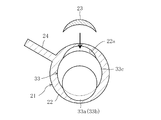
ここで、ピストン本体(22)を偏心部(33c)に組み付ける際には、軸方向から見てピストン本体(22)が駆動軸(33)の主軸部(33a)と重なり合わないように、ピストン本体(22)の凹部(22a)の位置合わせを行い、ピストン本体(22)を主軸部(33a)側から挿通させて偏心部(33c)に組み付ける(図4参照)。 Here, when assembling the piston body (22) to the eccentric part (33c), the piston body (22) is not overlapped with the main shaft part (33a) of the drive shaft (33) when viewed from the axial direction. The concave portion (22a) of the main body (22) is aligned, and the piston main body (22) is inserted from the main shaft portion (33a) side and assembled to the eccentric portion (33c) (see FIG. 4).
そして、駆動軸(33)を回転(又は、ピストン本体(22)を回転)させて、主軸部(33a)とピストン本体(22)の凹部(22a)とを周方向にずらした状態とする。そして、ピストン本体(22)の凹部(22a)と偏心部(33c)との隙間に嵌合部材(23)を嵌合させる(図5参照)。 Then, the drive shaft (33) is rotated (or the piston main body (22) is rotated) so that the main shaft portion (33a) and the concave portion (22a) of the piston main body (22) are shifted in the circumferential direction. And a fitting member (23) is fitted in the clearance gap between the recessed part (22a) and eccentric part (33c) of a piston main body (22) (refer FIG. 5).
なお、上側の圧縮機構(20)のピストン(21)では、上述したように、主軸部(33a)側から挿通させるが、下側の圧縮機構(20)のピストン(21)では、副軸部(33b)側から挿通させるようにすればよい。 As described above, the piston (21) of the upper compression mechanism (20) is inserted from the main shaft portion (33a) side, but the piston (21) of the lower compression mechanism (20) is inserted into the sub shaft portion. What is necessary is just to make it penetrate from the (33b) side.
これにより、駆動軸(33)の主軸部(33a)側からピストン(21)を挿通させる際に、ピストン(21)が主軸部(33a)と干渉することなく偏心部(33c)に嵌め込むことができる。また、従来のように偏心部(33c)の偏心量に応じて副軸部(33b)の軸径を小さくしなくても偏心部(33c)に対してピストン(21)を嵌め込むことができるので、駆動軸(33)の剛性を確保することができる。これにより、駆動軸(33)の撓みを抑制しつつピストン(21)の組付性の向上を図ることができる。 As a result, when the piston (21) is inserted from the main shaft portion (33a) side of the drive shaft (33), the piston (21) is fitted into the eccentric portion (33c) without interfering with the main shaft portion (33a). Can do. Further, the piston (21) can be fitted into the eccentric portion (33c) without reducing the shaft diameter of the auxiliary shaft portion (33b) according to the amount of eccentricity of the eccentric portion (33c) as in the prior art. Therefore, the rigidity of the drive shaft (33) can be ensured. Thereby, the assembly | attachment property of a piston (21) can be aimed at, suppressing the bending of a drive shaft (33).
ピストン本体(22)の凹部(22a)は、ブレード(24)とピストン(21)との境界位置から低圧室(L)側に向かうピストン(21)半周分の範囲内に配置される。このような構成とすれば、ブレード(24)とピストン(21)との境界位置から低圧室(L)側に向かうピストン(21)半周分の範囲内では、その反対側の範囲に比べて冷媒による圧力負荷が小さいため、ピストン本体(22)の凹部(22a)を高圧室(H)側に配置する場合に比べてピストン本体(22)の凹部(22a)に加わる応力を低減することができる。 The concave portion (22a) of the piston body (22) is disposed within a range of a half circumference of the piston (21) from the boundary position between the blade (24) and the piston (21) toward the low pressure chamber (L). In such a configuration, the refrigerant in the range of the half circumference of the piston (21) heading from the boundary position between the blade (24) and the piston (21) toward the low pressure chamber (L) side is larger than the range on the opposite side. Since the pressure load due to is small, the stress applied to the concave portion (22a) of the piston main body (22) can be reduced compared to the case where the concave portion (22a) of the piston main body (22) is arranged on the high pressure chamber (H) side. .
−運転動作−
本実施形態1に係る圧縮機(10)では、電動機(30)を起動すると、ロータ(32)が駆動軸(33)を回転させる。これにより、駆動軸(33)の偏心部(33c)は、主軸部(33a)及び副軸部(33b)の軸心回りに偏心回転する。そして、偏心部(33c)が偏心回転すると、各圧縮機構(20)において、ピストン(21)がシリンダ(25)内で揺動運動を行う。それぞれのピストン(21)の揺動運動に伴って、吸入管(12)を介して圧縮機(10)内に吸入された冷媒は、各シリンダ(25)の低圧室(L)に吸入される。
-Driving action-
In the compressor (10) according to the first embodiment, when the electric motor (30) is started, the rotor (32) rotates the drive shaft (33). Thereby, the eccentric part (33c) of the drive shaft (33) rotates eccentrically around the axis of the main shaft part (33a) and the auxiliary shaft part (33b). When the eccentric portion (33c) rotates eccentrically, the piston (21) performs a swinging motion in the cylinder (25) in each compression mechanism (20). As the piston (21) swings, the refrigerant sucked into the compressor (10) through the suction pipe (12) is sucked into the low pressure chamber (L) of each cylinder (25). .
圧縮機構(20)に吸入された冷媒は、各シリンダ(25)内においてピストン(21)が揺動して低圧室(L)と高圧室(H)の容積が変動することで圧縮される。低圧室(L)には、低圧室(L)の容積が拡大するにつれて冷媒が吸入される。一方、高圧室(H)では、高圧室(H)の容積が縮小するにつれて冷媒が圧縮される。そして、高圧室(H)の高圧冷媒が各吐出ポート(25b)に吐出される。 The refrigerant sucked into the compression mechanism (20) is compressed when the piston (21) swings in each cylinder (25) and the volumes of the low pressure chamber (L) and the high pressure chamber (H) fluctuate. The refrigerant is sucked into the low pressure chamber (L) as the volume of the low pressure chamber (L) increases. On the other hand, in the high pressure chamber (H), the refrigerant is compressed as the volume of the high pressure chamber (H) decreases. Then, the high-pressure refrigerant in the high-pressure chamber (H) is discharged to each discharge port (25b).
ここで、図6に示すように、ピストン(21)が揺動した場合でも、ブレード(24)によってピストン(21)が自転することが防止される。これにより、ピストン本体(22)の凹部(22a)は、常にブレード(24)とピストン(21)との境界位置から低圧室(L)側に向かうピストン(21)半周分の範囲内に位置することとなり、凹部(22a)に加わる応力が低減される。 Here, as shown in FIG. 6, even when the piston (21) swings, the blade (24) prevents the piston (21) from rotating. Thereby, the recessed part (22a) of the piston body (22) is always located within the range of a half circumference of the piston (21) from the boundary position between the blade (24) and the piston (21) toward the low pressure chamber (L). That is, the stress applied to the recess (22a) is reduced.
各吐出ポート(25b)に吐出された高圧の冷媒は、主軸受(41)に形成された吐出通路を通ってケーシング(11)の内部空間に吐出される。そして、ケーシング(11)の内部空間に吐出された高圧冷媒は、吐出管(13)を介して圧縮機(10)の外部に吐出される。 The high-pressure refrigerant discharged to each discharge port (25b) is discharged into the internal space of the casing (11) through the discharge passage formed in the main bearing (41). Then, the high-pressure refrigerant discharged into the internal space of the casing (11) is discharged outside the compressor (10) through the discharge pipe (13).
なお、ピストン本体(22)の凹部(22a)は、主軸部(33a)の外周面に対応させて湾曲状となるように形成しているが、ピストン本体(22)と主軸部(33a)とが軸方向から見て重なり合わなければ、どのような形状でもよい。 In addition, although the recessed part (22a) of the piston main body (22) is formed so as to be curved corresponding to the outer peripheral surface of the main shaft part (33a), the piston main body (22) and the main shaft part (33a) As long as they do not overlap when viewed from the axial direction, they may have any shape.
《実施形態2》
図7は、本実施形態2に係る圧縮機の圧縮機構の圧縮機構を拡大して示す図である。前記実施形態1との違いは、ピストン(21)とブレード(24)とが別体に形成されたロータリ型の圧縮機構(20)を備えた点であるため、以下、実施形態1と同じ部分については同じ符号を付し、相違点についてのみ説明する。
<< Embodiment 2 >>
FIG. 7 is an enlarged view of the compression mechanism of the compression mechanism of the compressor according to the second embodiment. Since the difference from the first embodiment is that the piston (21) and the blade (24) are provided with a rotary compression mechanism (20) formed separately, the same parts as those of the first embodiment will be described below. Are denoted by the same reference numerals, and only differences will be described.
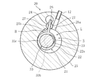
図7に示すように、圧縮機構(20)は、シリンダ室(S)を有するシリンダ(25)と、シリンダ室(S)内に収容されるピストン(21)と、シリンダ室(S)を低圧側の低圧室(L)と高圧側の高圧室(H)とに仕切るブレード(24)とを備えている。 As shown in FIG. 7, the compression mechanism (20) has a cylinder (25) having a cylinder chamber (S), a piston (21) accommodated in the cylinder chamber (S), and a low pressure in the cylinder chamber (S). A blade (24) for partitioning into a low pressure chamber (L) on the side and a high pressure chamber (H) on the high pressure side.
シリンダ(25)には、シリンダ(25)の径方向に沿ってブレード溝(28)が形成されている。このブレード溝(28)には、長方形の板状で且つ先端部(24a)が円弧状に形成されたブレード(24)がシリンダ(25)の径方向へ摺動可能に装着されている。ブレード(24)は、ブレード溝(28)内に設けられたスプリング(29)によって径方向内方へ付勢され、ブレード(24)の先端部(24a)が常にピストン(21)に接触した状態で、駆動軸(33)の回転に伴ってブレード溝(28)内を進退するように構成されている。 A blade groove (28) is formed in the cylinder (25) along the radial direction of the cylinder (25). In the blade groove (28), a blade (24) having a rectangular plate shape and a tip portion (24a) formed in an arc shape is mounted so as to be slidable in the radial direction of the cylinder (25). The blade (24) is urged radially inward by a spring (29) provided in the blade groove (28), and the tip (24a) of the blade (24) is always in contact with the piston (21). Thus, it is configured to advance and retract in the blade groove (28) as the drive shaft (33) rotates.
ピストン(21)は、リング状に形成され、いわゆるロータリピストンを構成している。ピストン(21)は、シリンダ(25)のシリンダ室(S)内に収容され、シリンダ(25)の内周面との間に圧縮室を形成している。 The piston (21) is formed in a ring shape and constitutes a so-called rotary piston. The piston (21) is accommodated in the cylinder chamber (S) of the cylinder (25), and forms a compression chamber between the piston (21) and the inner peripheral surface of the cylinder (25).
ピストン(21)は、ピストン本体(22)と、嵌合部材(23)とを有する。ピストン本体(22)には、軸方向から見て主軸部(33a)と重なり合わないように内周面の一部が窪んだ凹部(22a)が形成されている。嵌合部材(23)は、凹部(22a)と偏心部(33c)との間に着脱自在に嵌合されている。 The piston (21) has a piston body (22) and a fitting member (23). The piston body (22) has a recess (22a) in which a part of the inner peripheral surface is recessed so as not to overlap with the main shaft portion (33a) when viewed from the axial direction. The fitting member (23) is detachably fitted between the recess (22a) and the eccentric part (33c).
ピストン本体(22)の外周面には、摺接凹部(22b)が形成されている。この摺接凹部(22b)の内周面は湾曲状に形成され、摺接凹部(22b)内には、ブレード(24)の先端部(24a)が摺接自在に収容されている。これにより、駆動軸(33)の回転に伴うピストン(21)の自転をブレード(24)によって防止することができる。つまり、ブレード(24)の先端部(24a)と、ピストン本体(22)の摺接凹部(22b)とによって、ピストン(21)の自転を防止する自転防止機構(50)が構成されている。 A sliding contact recess (22b) is formed on the outer peripheral surface of the piston body (22). The inner peripheral surface of the sliding contact recess (22b) is formed in a curved shape, and the tip end portion (24a) of the blade (24) is slidably received in the sliding contact recess (22b). Thereby, rotation of the piston (21) accompanying rotation of the drive shaft (33) can be prevented by the blade (24). That is, the rotation preventing mechanism (50) for preventing the rotation of the piston (21) is constituted by the tip (24a) of the blade (24) and the sliding contact recess (22b) of the piston main body (22).
ピストン本体(22)の凹部(22a)は、ブレード(24)とピストン(21)との境界位置から低圧室(L)側に向かうピストン(21)半周分の範囲内に配置される。このような構成とすれば、ブレード(24)とピストン(21)との境界位置から低圧室(L)側に向かうピストン(21)半周分の範囲内では、その反対側の範囲に比べて冷媒による圧力負荷が小さいため、ピストン本体(22)の凹部(22a)を高圧室(H)側に配置する場合に比べてピストン本体(22)の凹部(22a)に加わる応力を低減することができる。 The concave portion (22a) of the piston body (22) is disposed within a range of a half circumference of the piston (21) from the boundary position between the blade (24) and the piston (21) toward the low pressure chamber (L). In such a configuration, the refrigerant in the range of the half circumference of the piston (21) heading from the boundary position between the blade (24) and the piston (21) toward the low pressure chamber (L) side is larger than the range on the opposite side. Since the pressure load due to is small, the stress applied to the concave portion (22a) of the piston main body (22) can be reduced compared to the case where the concave portion (22a) of the piston main body (22) is arranged on the high pressure chamber (H) side. .
−運転動作−
本実施形態2に係る圧縮機(10)では、電動機(30)を起動すると、ロータ(32)が駆動軸(33)を回転させる。これにより、駆動軸(33)の偏心部(33c)は、主軸部(33a)及び副軸部(33b)の軸心回りに偏心回転する。そして、偏心部(33c)が偏心回転すると、各圧縮機構(20)において、ピストン(21)がシリンダ(25)内で揺動運動を行う。それぞれのピストン(21)の揺動運動に伴って、吸入管(12)を介して圧縮機(10)内に吸入された冷媒は、各シリンダ(25)の低圧室(L)に吸入される。
-Driving action-
In the compressor (10) according to the second embodiment, when the electric motor (30) is started, the rotor (32) rotates the drive shaft (33). Thereby, the eccentric part (33c) of the drive shaft (33) rotates eccentrically around the axis of the main shaft part (33a) and the auxiliary shaft part (33b). When the eccentric portion (33c) rotates eccentrically, the piston (21) performs a swinging motion in the cylinder (25) in each compression mechanism (20). As the piston (21) swings, the refrigerant sucked into the compressor (10) through the suction pipe (12) is sucked into the low pressure chamber (L) of each cylinder (25). .
圧縮機構(20)に吸入された冷媒は、各シリンダ(25)内においてピストン(21)が偏心回転して低圧室(L)と高圧室(H)の容積が変動することで圧縮される。低圧室(L)には、低圧室(L)の容積が拡大するにつれて冷媒が吸入される。一方、高圧室(H)では、高圧室(H)の容積が縮小するにつれて冷媒が圧縮される。そして、高圧室(H)の高圧冷媒が各吐出ポート(25b)に吐出される。 The refrigerant sucked into the compression mechanism (20) is compressed as the piston (21) rotates eccentrically in each cylinder (25) and the volumes of the low pressure chamber (L) and the high pressure chamber (H) fluctuate. The refrigerant is sucked into the low pressure chamber (L) as the volume of the low pressure chamber (L) increases. On the other hand, in the high pressure chamber (H), the refrigerant is compressed as the volume of the high pressure chamber (H) decreases. Then, the high-pressure refrigerant in the high-pressure chamber (H) is discharged to each discharge port (25b).
ここで、図8に示すように、ピストン(21)が偏心回転した場合でも、ブレード(24)の先端部(24a)がピストン(21)の摺接凹部(22b)内で摺接することで、ピストン(21)が自転することが防止される。これにより、ピストン本体(22)の凹部(22a)は、常にブレード(24)とピストン(21)との境界位置から低圧室(L)側に向かうピストン(21)半周分の範囲内に位置することとなり、凹部(22a)に加わる応力が低減される。 Here, as shown in FIG. 8, even when the piston (21) rotates eccentrically, the tip (24a) of the blade (24) is in sliding contact within the sliding contact recess (22b) of the piston (21). The piston (21) is prevented from rotating. Thereby, the recessed part (22a) of the piston body (22) is always located within the range of a half circumference of the piston (21) from the boundary position between the blade (24) and the piston (21) toward the low pressure chamber (L). That is, the stress applied to the recess (22a) is reduced.
各吐出ポート(25b)に吐出された高圧の冷媒は、主軸受(41)に形成された吐出通路を通ってケーシング(11)の内部空間に吐出される。そして、ケーシング(11)の内部空間に吐出された高圧冷媒は、吐出管(13)を介して圧縮機(10)の外部に吐出される。 The high-pressure refrigerant discharged to each discharge port (25b) is discharged into the internal space of the casing (11) through the discharge passage formed in the main bearing (41). Then, the high-pressure refrigerant discharged into the internal space of the casing (11) is discharged outside the compressor (10) through the discharge pipe (13).
《その他の実施形態》
前記実施形態については、以下のような構成としてもよい。
<< Other Embodiments >>
About the said embodiment, it is good also as following structures.
前記実施形態では、圧縮機構(20)を2つ備えた多気筒型の圧縮機(10)について説明したが、圧縮機構(20)を1つのみ備えた単気筒型の圧縮機(10)であってもよい。 In the above embodiment, the multi-cylinder compressor (10) having two compression mechanisms (20) has been described. However, the single-cylinder compressor (10) having only one compression mechanism (20) is used. There may be.
また、ピストン(21)の自転防止機構(50)として、ブレード(24)の先端部(24a)をピストン本体(22)の摺接凹部(22b)に摺接自在に収容させた構成について説明したが、この形態に限定するものではなく、ピストン(21)の自転を防止することができれば、その他の構成を採用してもよい。 In addition, as the rotation prevention mechanism (50) of the piston (21), the configuration in which the tip (24a) of the blade (24) is slidably received in the sliding contact recess (22b) of the piston body (22) has been described. However, the present invention is not limited to this form, and other configurations may be adopted as long as the rotation of the piston (21) can be prevented.
以上説明したように、本発明は、駆動軸の撓みを抑制するとともにピストンの組付性の向上を図ることができるという実用性の高い効果が得られることから、きわめて有用で産業上の利用可能性は高い。 As described above, the present invention is extremely useful and industrially applicable because it has a highly practical effect of suppressing the bending of the drive shaft and improving the assembly of the piston. The nature is high.
10 圧縮機
20 圧縮機構
21 ピストン
22a 凹部
23 嵌合部材
24 ブレード
25 シリンダ
33 駆動軸
33a 主軸部
33c 偏心部
50 自転防止機構
S シリンダ室
L 低圧室
H 高圧室
10 Compressor
20 Compression mechanism
21 piston
22a recess
23 Mating member
24 blade
25 cylinders
33 Drive shaft
33a Main shaft
33c Eccentric part
50 Anti-rotation mechanism
S Cylinder chamber
L Low pressure chamber
H High pressure chamber
Claims (5)
前記駆動軸(33)は、前記主軸部(33a)の半径Rm、前記偏心部(33c)の半径Rc、該主軸部(33a)の回転中心に対する該偏心部(33c)の偏心量eが、Rc<(Rm+e)という条件を満たすように構成され、
前記ピストン(21)には、軸方向から見て前記主軸部(33a)と重なり合わないように内周面の一部が窪んだ凹部(22a)が形成されていることを特徴とする圧縮機。 A drive shaft (33) having a main shaft portion (33a) and an eccentric portion (33c) eccentric from the rotation center of the main shaft portion (33a) is fitted into the eccentric portion (33c) of the drive shaft (33). A compressor comprising a ring-shaped piston (21) and a cylinder (25) having a cylinder chamber (S) for accommodating the piston (21),
The drive shaft (33) has a radius Rm of the main shaft portion (33a), a radius Rc of the eccentric portion (33c), and an eccentricity amount e of the eccentric portion (33c) with respect to the rotation center of the main shaft portion (33a). Configured to satisfy the condition of Rc <(Rm + e),
The piston (21) is formed with a recess (22a) in which a part of the inner peripheral surface is recessed so as not to overlap the main shaft portion (33a) when viewed in the axial direction. .
前記シリンダ室(S)内を低圧室(L)と高圧室(H)とに区画するブレード(24)を備え、
前記ピストン(21)の凹部(22a)は、前記ブレード(24)と該ピストン(21)との境界位置から前記低圧室(L)側に向かう該ピストン(21)半周分の範囲内に配置されていることを特徴とする圧縮機。 In claim 1,
A blade (24) that divides the inside of the cylinder chamber (S) into a low pressure chamber (L) and a high pressure chamber (H);
The recess (22a) of the piston (21) is arranged within a range of a half circumference of the piston (21) from the boundary position between the blade (24) and the piston (21) toward the low pressure chamber (L). The compressor characterized by having.
前記凹部(22a)と前記偏心部(33c)との間に嵌合される嵌合部材(23)を備えたことを特徴とする圧縮機。 In claim 1 or 2,
A compressor comprising a fitting member (23) fitted between the concave portion (22a) and the eccentric portion (33c).
前記ピストン(21)に一体形成され、前記シリンダ室(S)内を低圧室(L)と高圧室(H)とに区画するブレード(24)を備え、
前記ピストン(21)は、前記シリンダ室(S)内で揺動自在な揺動型の圧縮機構(20)を構成していることを特徴とする圧縮機。 In any one of claims 1 to 3,
A blade (24) that is integrally formed with the piston (21) and divides the cylinder chamber (S) into a low pressure chamber (L) and a high pressure chamber (H);
The compressor characterized in that the piston (21) constitutes an oscillating compression mechanism (20) that can oscillate within the cylinder chamber (S).
前記ピストン(21)に摺接するように配置され、前記シリンダ室(S)内を低圧室(L)と高圧室(H)とに区画するブレード(24)と、
前記駆動軸(33)の回転に伴う前記ピストン(21)の自転を防止する自転防止機構(50)とを備え、
前記ピストン(21)は、前記シリンダ室(S)内で回転自在なロータリ型の圧縮機構(20)を構成していることを特徴とする圧縮機。 In any one of claims 1 to 3,
A blade (24) disposed so as to be in sliding contact with the piston (21) and dividing the inside of the cylinder chamber (S) into a low pressure chamber (L) and a high pressure chamber (H);
A rotation prevention mechanism (50) for preventing rotation of the piston (21) accompanying rotation of the drive shaft (33);
The compressor characterized in that the piston (21) constitutes a rotary compression mechanism (20) that is rotatable in the cylinder chamber (S).
Priority Applications (1)
| Application Number | Priority Date | Filing Date | Title |
|---|---|---|---|
| JP2010276691A JP2012127198A (en) | 2010-12-13 | 2010-12-13 | Compressor |
Applications Claiming Priority (1)
| Application Number | Priority Date | Filing Date | Title |
|---|---|---|---|
| JP2010276691A JP2012127198A (en) | 2010-12-13 | 2010-12-13 | Compressor |
Publications (1)
| Publication Number | Publication Date |
|---|---|
| JP2012127198A true JP2012127198A (en) | 2012-07-05 |
Family
ID=46644518
Family Applications (1)
| Application Number | Title | Priority Date | Filing Date |
|---|---|---|---|
| JP2010276691A Withdrawn JP2012127198A (en) | 2010-12-13 | 2010-12-13 | Compressor |
Country Status (1)
| Country | Link |
|---|---|
| JP (1) | JP2012127198A (en) |
Cited By (4)
| Publication number | Priority date | Publication date | Assignee | Title |
|---|---|---|---|---|
| JP2015017545A (en) * | 2013-07-11 | 2015-01-29 | 三菱電機株式会社 | Rotary compressor and manufacturing method thereof |
| WO2019031412A1 (en) * | 2017-08-09 | 2019-02-14 | ダイキン工業株式会社 | Rotary compressor |
| WO2019031411A1 (en) * | 2017-08-09 | 2019-02-14 | ダイキン工業株式会社 | Rotary compressor |
| FR3164737A1 (en) * | 2024-07-22 | 2026-01-23 | Valeo Japan Co., Ltd. | ROLLER PISTON COMPRESSOR |
-
2010
- 2010-12-13 JP JP2010276691A patent/JP2012127198A/en not_active Withdrawn
Cited By (11)
| Publication number | Priority date | Publication date | Assignee | Title |
|---|---|---|---|---|
| JP2015017545A (en) * | 2013-07-11 | 2015-01-29 | 三菱電機株式会社 | Rotary compressor and manufacturing method thereof |
| WO2019031412A1 (en) * | 2017-08-09 | 2019-02-14 | ダイキン工業株式会社 | Rotary compressor |
| WO2019031411A1 (en) * | 2017-08-09 | 2019-02-14 | ダイキン工業株式会社 | Rotary compressor |
| JP2019031951A (en) * | 2017-08-09 | 2019-02-28 | ダイキン工業株式会社 | Rotary Compressor |
| JP2019031952A (en) * | 2017-08-09 | 2019-02-28 | ダイキン工業株式会社 | Rotary Compressor |
| CN110998095A (en) * | 2017-08-09 | 2020-04-10 | 大金工业株式会社 | Rotary compressor |
| EP3647595A4 (en) * | 2017-08-09 | 2020-11-18 | Daikin Industries, Ltd. | ROTARY COMPRESSOR |
| US11473581B2 (en) | 2017-08-09 | 2022-10-18 | Daikin Industries, Ltd. | Rotary compressor |
| US11835044B2 (en) | 2017-08-09 | 2023-12-05 | Daikin Industries, Ltd. | Rotary compressor |
| FR3164737A1 (en) * | 2024-07-22 | 2026-01-23 | Valeo Japan Co., Ltd. | ROLLER PISTON COMPRESSOR |
| EP4685352A1 (en) * | 2024-07-22 | 2026-01-28 | Valeo Japan Co., Ltd. | Rolling piston compressor |
Similar Documents
| Publication | Publication Date | Title |
|---|---|---|
| JP2012127198A (en) | Compressor | |
| US11473581B2 (en) | Rotary compressor | |
| JP6340964B2 (en) | Rotary compressor | |
| JP6090379B2 (en) | Rotary compressor | |
| JP2012127199A (en) | Compressor | |
| US11835044B2 (en) | Rotary compressor | |
| JP2019039418A (en) | Rotary compressor | |
| JP2019031949A (en) | Rotary Compressor | |
| JP2012127200A (en) | Compressor | |
| JP6464583B2 (en) | Rotary compressor | |
| JP2007113489A (en) | Rotary compressor | |
| JP2013253568A (en) | Two stage compressor | |
| JP5915175B2 (en) | Rotary compressor | |
| WO2018142536A1 (en) | Compressor | |
| JP2017082840A (en) | Bearing structure and scroll type compressor | |
| JP2017082842A (en) | Bearing structure and scroll compressor | |
| JP2017008826A (en) | Rotary type compressor | |
| JP5861458B2 (en) | Swing piston compressor | |
| JP2017008819A (en) | Rotary compressor | |
| JP2008082267A (en) | Compressor | |
| JP2017082841A (en) | Bearing structure and scroll compressor | |
| JP2013139724A (en) | Oscillating piston type compressor | |
| JP2020012428A (en) | Rotary compressor | |
| JP2007113493A (en) | Rotary compressor | |
| JP2016094848A (en) | Compressor |
Legal Events
| Date | Code | Title | Description |
|---|---|---|---|
| A300 | Withdrawal of application because of no request for examination |
Free format text: JAPANESE INTERMEDIATE CODE: A300 Effective date: 20140304 |