JP2012129904A - Electronic apparatus - Google Patents
Electronic apparatus Download PDFInfo
- Publication number
- JP2012129904A JP2012129904A JP2010281336A JP2010281336A JP2012129904A JP 2012129904 A JP2012129904 A JP 2012129904A JP 2010281336 A JP2010281336 A JP 2010281336A JP 2010281336 A JP2010281336 A JP 2010281336A JP 2012129904 A JP2012129904 A JP 2012129904A
- Authority
- JP
- Japan
- Prior art keywords
- vibrating
- base
- arm
- vibrating arm
- electronic device
- Prior art date
- Legal status (The legal status is an assumption and is not a legal conclusion. Google has not performed a legal analysis and makes no representation as to the accuracy of the status listed.)
- Pending
Links
Images


Landscapes
- Piezo-Electric Or Mechanical Vibrators, Or Delay Or Filter Circuits (AREA)
- Oscillators With Electromechanical Resonators (AREA)
Abstract
【課題】振動片を備え、小型で、低周波数化および高Q値化が図られた、電子機器を提供する。
【解決手段】電子機器に備えられる振動片20は、一対の切り込み31が形成された基部21と、基部21の第1の部分の一端側から互いに平行に延出された一対の振動腕22と、を有している。各振動腕22は、主要な振動部である一般部23と、振動腕22の基部21との付け根とは反対側の先端側に、一般部23よりも幅が広い錘部29と、を有している。また、各振動腕22の両主面のうち少なくとも一方の主面に沿って開口部を有する有底の長溝と、前記振動腕の前記基部との付け根とは反対側の先端側に、前記基部との前記付け根側よりも幅が広い錘部29が形成されている。錘部29は、振動腕22の長手方向において、基部21との付け根から先端側までの長さに占める錘部29の長さ割合が35%〜41%の範囲となるように形成されている。
【選択図】図1An electronic device including a resonator element and having a small size, a low frequency, and a high Q value is provided.
A vibrating piece 20 provided in an electronic device includes a base portion 21 having a pair of cuts 31 and a pair of vibrating arms 22 extending in parallel from one end side of a first portion of the base portion 21. ,have. Each vibrating arm 22 has a general portion 23 that is a main vibrating portion, and a weight portion 29 that is wider than the general portion 23 on the tip side opposite to the base of the vibrating arm 22 with the base 21. is doing. Further, the base portion is formed on the distal end side of the vibrating arm 22 opposite to the base of the bottom portion of the vibrating arm and the base portion of the vibrating arm along at least one main surface of the main surfaces. A weight portion 29 having a width wider than that of the base side is formed. The weight portion 29 is formed such that, in the longitudinal direction of the vibrating arm 22, the length ratio of the weight portion 29 occupying the length from the base to the distal end side with the base portion 21 is in a range of 35% to 41%. .
[Selection] Figure 1
Description
本発明は、例えば、屈曲振動モードで振動する屈曲振動片などの振動片を備えた電子機器に関する。 The present invention relates to an electronic apparatus including a vibrating piece such as a bending vibrating piece that vibrates in a bending vibration mode.
従来より、屈曲振動モードで振動し電子機器に備えることが可能な振動片には、例えば、水晶のような圧電材料からなる基材の基部から一対の振動腕を平行に延出させて、且つ、水平方向に互いに接近または離反する向きに振動させる音叉型の屈曲振動片が広く使用されている。この音叉型屈曲振動片の振動腕を励振させたとき、その振動エネルギーに損失が生じると、CI(Crystal Impedance)値の増大やQ値の低下など、振動片の性能を低下させる原因となる。そこで、そのような振動エネルギーの損失を防止または低減するために、従来から様々な工夫がなされている。 Conventionally, for a vibrating piece that vibrates in a bending vibration mode and can be provided in an electronic device, for example, a pair of vibrating arms are extended in parallel from the base of a base material made of a piezoelectric material such as quartz, and Tuning-fork-type bending vibration pieces that vibrate in directions toward or away from each other in the horizontal direction are widely used. When the vibration arm of the tuning-fork type bending vibration piece is excited, if the vibration energy is lost, it causes a decrease in the performance of the vibration piece, such as an increase in CI (Crystal Impedance) value and a decrease in Q value. Therefore, various ideas have been conventionally made in order to prevent or reduce such loss of vibration energy.
例えば、振動腕が延出する基部の両側部に切込み部または所定の深さの切り込み(切り込み溝)を形成した音叉型の水晶振動片が知られている(例えば特許文献1、特許文献2を参照)。この音叉型水晶振動片は、振動腕の振動が垂直方向の成分をも含む場合に、振動が基部から漏れるのを切り込みにより緩和することによって、振動エネルギーの閉じ込め効果を高めてQ値を制御し、且つ、振動片間でのQ値のばらつきを防止している。 For example, there are known tuning-fork type crystal vibrating pieces in which cut portions or cuts (cut grooves) having a predetermined depth are formed on both sides of a base portion from which a vibrating arm extends (for example, Patent Document 1 and Patent Document 2). reference). This tuning-fork type crystal resonator element controls the Q value by enhancing the confinement effect of vibration energy by mitigating the leakage of vibration from the base by cutting when the vibration of the vibrating arm also includes a vertical component. In addition, variations in the Q value between the resonator elements are prevented.
また、振動片においては、上記のような機械的な振動エネルギーの損失だけでなく、屈曲運動する振動腕の圧縮応力が作用する圧縮部と引張応力が作用する伸張部との間で発生する温度差による熱伝導によっても発生する。この熱伝導によって生じるQ値の低下は熱弾性損失効果と呼ばれている。
熱弾性損失効果によるQ値の低下を防止または抑制するために、矩形断面を有する振動腕(振動梁)の中心線上に溝、または孔を形成した音叉型の振動片が、例えば特許文献3に紹介されている。
In the resonator element, not only the loss of mechanical vibration energy as described above, but also the temperature generated between the compressive portion where the compressive stress of the vibrating arm which is bent and acting and the extension portion where the tensile stress acts. It is also caused by heat conduction due to the difference. This decrease in the Q value caused by heat conduction is called a thermoelastic loss effect.
In order to prevent or suppress a decrease in the Q value due to the thermoelastic loss effect, a tuning-fork type vibration piece in which a groove or a hole is formed on the center line of a vibrating arm (vibrating beam) having a rectangular cross section is disclosed in Patent Document 3, for example. It has been introduced.
ところで、振動片を備えた種々の電子機器、例えば、HDD(ハード・ディスク・ドライブ)、モバイルコンピューター、あるいはICカード等の小型の情報機器や、携帯電話、自動車電話、またはページングシステム等の移動体通信機器や振動ジャイロセンサー等の小型化が、近年ますます進展している。これに伴って、それらの電子機器に取り付けられる振動片の小型化の要求がより一層高まってきている。
このような振動片の小型化への要求のなかでは、特に、振動腕の長さを短くすることが寄与率が高く、また、それに伴い、振動腕の断面積を小さくすることが要求される。このため、振動片の低周波数化を図ることが困難になり、また、高次振動モードが発生するなどして振動片の振動特性が不安定になりやすくなることが知られている。このような高次振動モードの発生を抑えたり、低周波数化や振動特性の安定化を図り得る振動片として、振動腕の先端部に、振動腕の一般部(腕部)よりも幅の大きい錘部を形成した振動片が、例えば特許文献4に紹介されている。
By the way, various electronic devices including a resonator element, for example, a small information device such as an HDD (hard disk drive), a mobile computer, or an IC card, or a mobile body such as a mobile phone, a car phone, or a paging system. In recent years, miniaturization of communication devices, vibration gyro sensors, and the like has progressed more and more. In connection with this, the request | requirement of size reduction of the vibration piece attached to those electronic devices has increased further.
Among the demands for downsizing of the resonator element, in particular, reducing the length of the vibrating arm has a high contribution rate, and accordingly, it is required to reduce the cross-sectional area of the vibrating arm. . For this reason, it is known that it is difficult to lower the frequency of the resonator element, and the vibration characteristics of the resonator element are likely to become unstable due to the occurrence of a higher-order vibration mode. As a resonating piece that can suppress the occurrence of such higher-order vibration modes and can reduce the frequency and stabilize vibration characteristics, the tip of the resonating arm is wider than the general part (arm part) of the resonating arm. For example, Patent Literature 4 introduces a resonator element in which a weight portion is formed.
しかしながら、電子機器に備えることが可能な振動片において、長溝と錘部とを兼ね備えた振動腕を有する構成とした場合、振動腕の長手方向の全長に対する錘部の長さの占有率が小さ過ぎたり、あるいは大き過ぎたりすると、錘部による低周波数化や長溝による熱弾性損失の抑制効果を所望のレベルで図ることはできないことを、発明者は見出した。また、発明者は、振動腕の長手方向の全長に対する錘部の長さの占有率が或る範囲にある場合に、所望の低周波数化、および、熱弾性損失の抑制効果による所望のQ値の確保ができることを見出した。 However, when the vibrating piece that can be provided in the electronic device has a vibrating arm that has both the long groove and the weight portion, the occupation ratio of the length of the weight portion with respect to the entire length in the longitudinal direction of the vibrating arm is too small. The inventor has found that the effect of reducing the frequency by the weight portion and suppressing the thermoelastic loss by the long groove cannot be achieved at a desired level if the weight is too large or too large. Further, the inventor has a desired Q value due to a desired low frequency and a thermoelastic loss suppression effect when the occupation ratio of the length of the weight portion with respect to the entire length in the longitudinal direction of the vibrating arm is within a certain range. It was found that it can be secured.
本発明は、上述の課題の少なくとも一部を解決するためになされたものであり、以下の形態または適用例として実現することが可能である。 SUMMARY An advantage of some aspects of the invention is to solve at least a part of the problems described above, and the invention can be implemented as the following forms or application examples.
〔適用例1〕本適用例にかかる電子機器は、振動片と、前記振動片と電気的に接続する回路部と、を有し、前記振動片は、基部と、前記基部から延出された振動腕と、を有し、前記振動腕には、前記振動腕の両主面のうち少なくとも一方の主面に沿って開口部を有する有底の長溝が設けられ、前記振動腕は、前記振動腕の前記基部との付け根とは反対側の先端側に、前記振動腕の前記基部との付け根側よりも幅が広い錘部が設けられ、前記振動腕の長手方向において、前記基部との付け根から前記先端側までの長さに占める前記錘部の長さの割合が35%〜41%の範囲にあることを特徴とする。 Application Example 1 An electronic apparatus according to this application example includes a resonator element and a circuit unit electrically connected to the resonator element, and the resonator element extends from the base part and the base part. A resonating arm, and the resonating arm is provided with a bottomed long groove having an opening along at least one of the main surfaces of the resonating arm. A weight portion having a width wider than the base side of the vibrating arm and the base side of the vibrating arm is provided on the tip side opposite to the base of the base of the arm, and in the longitudinal direction of the vibrating arm, The ratio of the length of the weight part to the length from the tip side to the tip side is in the range of 35% to 41%.
この構成によれば、電子機器に備えられている振動片において、振動腕に設けられた長溝によって、振動効率が向上しCI値が低減されるとともに、振動腕の先端部分の錘部が錘の機能を果たすことにより、振動腕の長さを増大させることなく周波数を十分に低く抑えられる効果が得られ、さらに、熱弾性損失が小さくなって、Q値の低下が十分に抑えられる効果が得られることを発明者は見出した。したがって、小型化を実現しながら、低周波数化が図られるとともに、Q値の低下が抑えられ、優れた振動特性を備えた振動片を提供することができる。これにより、電子機器の小型化の推進および信頼性の向上を図ることができる。 According to this configuration, in the resonator element provided in the electronic device, the vibration efficiency is improved and the CI value is reduced by the long groove provided in the resonator arm, and the weight portion of the tip portion of the resonator arm is By fulfilling the function, it is possible to obtain the effect of suppressing the frequency sufficiently low without increasing the length of the vibrating arm, and the effect of sufficiently reducing the Q value by reducing the thermoelastic loss. The inventor has found that Accordingly, it is possible to provide a resonator element having excellent vibration characteristics while achieving a reduction in frequency while achieving a reduction in size and suppressing a decrease in the Q value. As a result, it is possible to promote downsizing of electronic devices and improve reliability.
〔適用例2〕上記適用例にかかる電子機器において、前記錘部の前記長さの割合が36%〜40%の範囲にあることを特徴とする。 Application Example 2 In the electronic device according to the application example described above, the length ratio of the weight portion is in a range of 36% to 40%.
この構成によれば、小型化、低周波数化、およびQ値の低下の抑制の効果が顕著になる。 According to this configuration, the effects of downsizing, lowering the frequency, and suppressing the decrease in the Q value become significant.
〔適用例3〕上記適用例にかかる電子機器において、前記錘部の前記長さの割合が37%〜39%の範囲にあることを特徴とする。 Application Example 3 In the electronic device according to the application example described above, the length ratio of the weight portion is in a range of 37% to 39%.
この構成によれば、小型化、低周波数化、およびQ値の低下の抑制の効果がより顕著になる。 According to this configuration, the effects of downsizing, lowering the frequency, and suppressing the decrease in the Q value become more prominent.
〔適用例4〕上記適用例にかかる電子機器において、前記振動片は、前記基部から延出された2つの前記振動腕と、前記基部の2つの前記振動腕の間から、前記振動腕の前記長手方向に沿って延出して設けられている支持腕と、を備えていることを特徴とする。 Application Example 4 In the electronic device according to the application example described above, the vibrating piece includes the two vibrating arms extended from the base and the two vibrating arms of the base between the vibrating arms of the vibrating arm. And a support arm that extends along the longitudinal direction.
この構成によれば、電子機器に備えられている振動片は、支持腕が一対の振動腕間に設けられていることにより、各振動腕が振動した際に、特に、各振動腕が互いに接近する向きに振動したときに、各振動腕間の空気がかき乱されることによって起こる振動片の動作パラメーターの変化を抑制することができる。
また、基部を支持部としてパッケージなどに支持・固定させた場合に起こる様々な不具合、例えば、振動片の先端が下方に傾いてパッケージなどに接触することを防止できたり、パッケージへの衝撃が基部を介してダイレクトに振動腕に伝わることによって起こり得る動作異常などを回避したりすることが可能になり、振動特性の安定した振動片を提供することができる。この振動片を備えた電子機器は、高い信頼性を保持することができる。
According to this configuration, since the vibrating piece provided in the electronic device is provided with the support arm between the pair of vibrating arms, particularly when the vibrating arms vibrate, the vibrating arms approach each other. When the vibration is caused to occur, the change in the operating parameter of the resonator element caused by the air between the vibrating arms being disturbed can be suppressed.
In addition, various problems that occur when the base is supported and fixed to a package or the like with the base as a support, for example, the tip of the vibrating piece can be prevented from tilting downward and touching the package or the impact on the package can be prevented. Therefore, it is possible to avoid an abnormal operation that may occur by being directly transmitted to the vibrating arm via the arm, and to provide a vibrating piece with stable vibration characteristics. An electronic device provided with this resonator element can maintain high reliability.
〔適用例5〕上記適用例にかかる電子機器において、前記振動片の前記基部と前記振動腕とが水晶により形成されていることを特徴とする Application Example 5 In the electronic device according to the application example, the base portion and the vibrating arm of the vibrating piece are formed of quartz.
この構成によれば、耐衝撃性が高いとともに、熱弾性損失によるQ値の低下が抑えられ優れた振動特性を備えた、水晶振動片を提供することができる。この水晶振動片を備えた電子機器は、より高い信頼性を保持することができる。 According to this configuration, it is possible to provide a quartz crystal resonator element that has high impact resistance and has excellent vibration characteristics in which a decrease in Q value due to thermoelastic loss is suppressed. The electronic device provided with this crystal vibrating piece can maintain higher reliability.
〔適用例6〕上記適用例にかかる電子機器において、前記振動片が屈曲振動モードを呈する屈曲振動片であることを特徴とする。 Application Example 6 In the electronic device according to the application example described above, the vibration piece is a bending vibration piece exhibiting a bending vibration mode.
この構成によれば、電子機器に備えることが可能で、屈曲振動モードを呈する屈曲振動片において、低周波数化と同時にQ値の低下を抑える効果をより顕著に奏することを発明者は見出した。 According to this configuration, the inventor has found that the bending vibration piece that can be provided in an electronic device and exhibits a bending vibration mode exhibits the effect of suppressing the decrease in the Q value at the same time as lowering the frequency.
以下、本発明の電子機器の一実施形態について図面を参照しながら説明する。この電子機器は、優れた振動特性を有する振動片を備えていることが特徴である。
(実施形態)
Hereinafter, an electronic device according to an embodiment of the present invention will be described with reference to the drawings. This electronic device is characterized by including a resonator element having excellent vibration characteristics.
(Embodiment)
〔振動片〕
まず、本発明の電子機器の説明に先だって、電子機器に備えられている振動片について説明する。
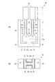
図1は、本実施形態の振動片を模式的に説明するものであり、(a)は、一方の主面側の平面図、(b)は、(a)のA−A線断面を示す断面拡大図である。
図1(a)において、本実施形態の振動片20は、水晶、タンタル酸リチウム、ニオブ酸リチウムなどの圧電材料からなる、屈曲振動モードを呈する振動片である。振動片20を水晶から構成する場合、水晶ウェハは、X軸、Y軸、およびZ軸からなる直交座標系において、Z軸を中心に時計回りに0度〜5度の範囲で回転させて切り出した水晶Z板を、所定の厚みに切断研磨加工して得られるものを用いる。本実施形態の振動片20は、その水晶Z板を加工することにより形成された基部21と、この基部21の一端側(図において上端側)から二股に別れて互いに平行に延出する一対の振動腕22とからなる所謂音叉型の外形を有して形成されている、水晶振動片である。
[Vibration piece]
First, prior to the description of the electronic device of the present invention, a resonator element provided in the electronic device will be described.
1A and 1B schematically illustrate a resonator element according to the present embodiment. FIG. 1A is a plan view of one main surface side, and FIG. 1B is a cross-sectional view taken along line AA in FIG. It is a cross-sectional enlarged view.
In FIG. 1A, the
基部21には、その両主面に括れた形状が表れるように1つの直線に沿って対向方向に一対の切り込み31が形成されている。基部21は、一対の切り込み31を挟んで両側に位置する第1の部分21aおよび第2の部分21bと、一対の切り込み31間で第1の部分21aおよび第2の部分21bを接続する接続部分21cとを含む。本実施形態の振動片20においては、この切り込み31によって、各振動腕22の振動の伝達が遮断されるので、振動が基部21や支持腕30を介して外部に伝わる所謂振動漏れを抑制し、CI値の上昇を防止することができる。
なお、各切り込み31は、振動片20の落下に対する強度の確保をした上で、最適な幅や長さに調整して振動漏れを最小にするのが望ましい。
The
In addition, it is desirable that each
図1(a)に示すように、一対の振動腕22は、基部21の第1の部分21aから両主面(紙面上手前と奥の面)に平行に延出されている。また、各振動腕22は、前記両主面と、その両主面を両側で接続する両側面とを有する。
各振動腕22は、その中央部に、振動腕22において主要な振動部である一般部23を有している。また、各振動腕22は、基部21に接続される根元部において、一般部23から基部21側に向けて前記両側面間の幅が徐徐に広げられ基部21との付け根部で最も幅広となる幅広部24を有している。このように、各振動腕22が幅広部24を有することにより、広い幅で基部21に接続されるので剛性が高くなり、耐衝撃性などが向上する。
As shown in FIG. 1A, the pair of vibrating
Each vibrating
また、各振動腕22の基部21の付け根とは反対側の先端側には、一般部23よりも幅が広い錘部29がそれぞれ形成されている。このように、各振動腕22の先端部分に錘部29が設けられていることにより、先端部分が錘の機能を果たすので、振動腕22の長さを増大させることなく周波数を低くすることができる。
また、振動片20の各振動腕22の長手方向(本例では、基部21の第1の部分21aから各振動腕22が延出される方向)において、基部21との付け根から先端側までの長さLに占める錘部29の長さlの割合が35%〜41%の範囲に調整されて設けられている。このような構成とすることにより、振動片20は、各振動腕22の先端部分の錘部29が錘の機能を果たすことにより、振動腕22の長さを増大させることなく周波数を十分に低く抑えられる効果が得られるとともに、熱弾性損失が小さくなってQ値の低下が十分に抑えられる効果が得られることを発明者は見出した(詳細は後述する)。
Further, a
Further, in the longitudinal direction of each vibrating
各振動腕22の一方の主面には、それぞれの長手方向に沿って一本の有底の長溝26aが設けられている。また、図1(b)に示すように、一方の(図1(a)の紙面上左側の)振動腕22の他方の主面にも、振動腕22の長手方向に沿って一本の長溝26bが設けられている。同様に、図示はしないが、他方の振動腕22(紙面上右側の振動腕)の他方の主面にも、1本の有底の溝26bが設けられている。即ち、長溝26a,26bは、主面に沿って位置する開口部をそれぞれ有している。
このように、各振動腕22に設けられた長溝26a,26bによって、剛性が小さくなって振動しやすくなり、振動腕22が効率よく振動して良好な振動特性を示すことが可能になる。また、長溝26a,26bは、各振動腕22の基部21との付け根部近傍において、振動に伴なう歪により振動腕22の両側面の突堤部25で発生する温度上昇および温度低下に起因する熱の流路を狭めているので、熱の移動を抑制して熱弾性損失を低減する効果を奏し、この結果、CI値の増大やQ値の低下などの熱弾性損失による悪影響を抑制できる。
One main surface of each vibrating
As described above, the
本実施形態の振動片20は、基部21の第2の部分21bから延びる一対の支持腕30を有している。一対の支持腕30は、基部21から一対の振動腕22が延びる方向とは交差方向であって、それぞれ相互に反対方向に延出されてから、屈曲部32で略直角に屈曲され、一対の振動腕22の延出方向と平行な方向に延びている。このように屈曲させることにより、支持腕30を有する振動片20の小型化を図ることができる。支持腕30は、屈曲部32よりも先端側(振動腕22の錘部29側)に、後述するようにパッケージなどに取り付けられる固定領域を含み、この支持腕30の固定領域で振動片20を支持するように取り付けることによって、振動腕22および基部21を振動片20の固定面から浮いた状態にすることができる。
The
各振動腕22の各長溝26a,26b、および各両側面を含む表面には、励振電極33,34が形成されている(図1(b)を参照)。一方の振動腕22において、励振電極33,34間に電圧を印加して、振動腕22の両側面を伸縮させることで振動腕22を振動させる。励振電極33,34は、水晶をエッチングして振動片20の長溝26a,26bを含む外形を形成した後で、例えば、ニッケル(Ni)またはクロム(Cr)を下地層として、その上に、蒸着またはスパッタリングにより例えば金(Au)による電極層を成膜し、その後フォトリソグラフィを用いてパターニングすることにより形成することができる。ここで、クロムは水晶との密着性が高く、また、金は、電気抵抗が低く酸化し難いことで知られている。
ここで、本実施形態の振動片20の効果について述べる。
発明者は、まず、振動腕22の基部21との付け根から先端部までの長さLに対する錘部29の長さlの占有率を変化させた時に、低周波数化が効率よく図れる占有率と、周波数一定に換算したQ値の低下を効率よく軽減できる占有率とをシミュレーションにより個別に求めた。その結果、低周波数化が効率よく図れる占有率と、Q値の低下を効率よく軽減できる占有率とは、一致しなかった。
次に、そのような、振動腕22の基部21との付け根から先端までの長さに対する錘部29の長さの占有率により、振動片20の低周波数化の効率が良くなる要素と、熱弾性損失がより小さくなる要素とを掛け合わせ、さらに、等価モデルでシミュレーションすることによって求めた最適値と合うように補正した結果、図2のグラフに示すような結果を得た。
図2において、横軸は、振動腕22の基部21との付け根から先端までの長手方向の長さLに対して錘部29の長さlが占める錘部占有率(%)であり、縦軸は、低周波数化指数と高Q値化指数とを掛けた値として定義する(補正後)修正高性能化指数である。
図2のグラフに示すように、補正後の高性能化指数は、錘部占有率38%を中心として錘部占有率35%〜41%のときに最も高いことを発明者は見出した。
Here, the effect of the
The inventor firstly occupies the occupancy ratio that can efficiently reduce the frequency when the occupancy ratio of the length l of the
Next, due to the occupancy ratio of the length of the
In FIG. 2, the horizontal axis represents the weight occupation ratio (%) occupied by the length l of the
As shown in the graph of FIG. 2, the inventor has found that the high performance index after correction is highest when the weight occupation ratio is 35% to 41% centering on the weight occupation ratio 38%.
なお、低周波数化指数とは、錘部による周波数の低下量を示す値であり、0〜1の規格化された値である。具体的には、低周波数化指数は、錘部占有率を0%〜100%の間で変化させた場合に、周波数が最も低くなったときを1とし、最も高くなったときを0として規格化した値である。
また、高Q値化指数とは、錘部によるQ値の上昇量を示す値であり、0〜1の規格化された値である。具体的には、高Q値化指数は、錘部占有率を0%〜100%の間で変化させた場合に、Q値が最も高くなったときを1とし、最も低くなったときを0として規格化した値である。
The frequency reduction index is a value indicating the amount of frequency decrease due to the weight portion, and is a normalized value of 0 to 1. Specifically, the frequency reduction index is defined as 1 when the frequency is lowest and 0 when it is highest when the weight occupation ratio is changed between 0% and 100%. It is a converted value.
Further, the high Q value index is a value indicating an increase amount of the Q value by the weight portion, and is a normalized value of 0 to 1. Specifically, the high Q value index is 1 when the Q value is the highest and 0 when the weight occupancy is changed between 0% and 100%. As a standardized value.
したがって、上記実施形態の振動片20によれば、各振動腕22に設けられた長溝26a,26bによって振動効率が向上しCI値が低減されるとともに、各振動腕22の先端部分に形成された錘部29の長手方向の長さlが、振動腕22の全長Lに対して35〜41%の占有率になるように形成されているので、振動腕22の長さを増大させることなく周波数を十分に低く抑えられるとともに、熱弾性損失が小さくなってQ値の低下を十分に抑える効果が得られる。
この効果は、各振動腕22の錘部29の錘部占有率を36%〜40%とすれば、より高まることを発明者は見出した。
更に、この効果は、各振動腕22の錘部29の錘部占有率を37%〜39%とすれば、より顕著に高まることを発明者は見出した。
Therefore, according to the
The inventor has found that this effect is further enhanced if the weight portion occupation ratio of the
Furthermore, the inventor has found that this effect is more markedly increased when the weight portion occupancy of the
〔振動子〕
次に、上記の振動片20を用いた振動子について説明する。
図3は、上記の振動片20を搭載する振動子の一実施形態を説明するものであり、(a)は上側からみた概略平面図、(b)は(a)のB−B線断面図である。なお、図3(a)では、振動子の内部の構造を説明する便宜上、振動子200の上方に設けられるリッド119(図3(b)を参照)を取り外した状態を図示している。
[Vibrator]
Next, a vibrator using the vibrating
FIGS. 3A and 3B illustrate an embodiment of a vibrator on which the
図3において、振動子200は、段差を有する凹部が設けられたパッケージ110を有している。パッケージ110の凹部の凹底部分には、振動片20が接合され、パッケージ110の開放された上端には、蓋体としてのリッド119が接合されている。
In FIG. 3, the
パッケージ110は、平板状の第1層基板111上に、内環状部の大きさが異なる矩形環状の第2層基板112および第3層基板113がこの順に積層されて構成されることにより、上面側に開口を有し内部に段差が設けられた凹部が形成されている。パッケージ110の材質としては、例えば、セラミック、ガラスなどを用いることができる。
The
パッケージ110の凹部において、第2層基板112により形成される段差上には、振動片20が接合される複数の振動片接続端子115が設けられている。また、図示はしないが、パッケージ110の外底面となる第1層基板111の外底面には、外部基板との接合に供する外部実装端子が設けられている。
このようにパッケージ110に設けられた上記の各種端子は、対応する端子どうしが、図示しない引き回し配線やスルーホールなどの層内配線により接続されている。
In the recess of the
As described above, the various terminals provided in the
パッケージ110の凹部には、振動片20が接合されている。具体的には、振動片20の支持腕30の一部に設けられた図示しない外部接続電極と、パッケージ110の凹部において、第2層基板112の突部112aにより形成された段差上に設けられた振動片接続端子115と、が位置合わせされ、例えば銀ペーストなどの導電性の接合部材96により接合されるとともに、電気的に接続されている。これにより、振動片20が、パッケージ110内において、凹部の凹底部分となる第1層基板111との間に隙間を空けながら、振動腕22を自由端として固定される。
The
図3(b)に示すように、振動片20が凹部内に接合されたパッケージ110の上端には、蓋体としてのリッド119が配置され、パッケージ110の開口を封鎖している。リッド119の材質としては、例えば、42アロイ(鉄にニッケルが42%含有された合金)やコバール(鉄、ニッケルおよびコバルトの合金)等の金属、セラミックス、あるいはガラスなどを用いることができる。例えば、金属からなるリッド119は、コバール合金などを矩形環状に型抜きして形成されたシールリング118を介してシーム溶接することによりパッケージ110と接合される。パッケージ110内に形成される内部空間は、振動片20が動作するための空間となる。また、この内部空間は、減圧空間または不活性ガス雰囲気に密閉・封止されている。
As shown in FIG. 3B, a
上記構成の振動子200によれば、上記した構成の振動片20を備えているので、振動腕22に設けられた長溝26a,26bによって、振動効率が向上されてCI値の低減が図られるとともに、錘部29による低周波数化および高Q値化が図られた優れた振動特性を備えた振動子200を提供することができる。
According to the
〔発振器〕
次に、上記の振動片20を用いた発振器について説明する。
図4は、上記の振動片20を搭載する発振器の一実施形態を説明するものであり、(a)は上側からみた概略平面図、(b)は(a)のC−C線断面図である。なお、図4(a)では、発振器の内部の構造を説明する便宜上、発振器300の上方に設けられるリッド219を取り外した状態を図示している。
[Oscillator]
Next, an oscillator using the vibrating
FIGS. 4A and 4B illustrate an embodiment of an oscillator on which the
図4において、発振器300は、段差を有する凹部が設けられたパッケージ210を有している。パッケージ210の凹部の凹底部分には、ICチップ150と、ICチップ150の上方に配置された振動片20とが接合され、パッケージ210の開放された上端には蓋体としてのリッド219が接合されている。
In FIG. 4, the
パッケージ210は、平板状の第1層基板211上に、内環状部の大きさが異なる矩形環状の第2層基板212、第3層基板213、および第4層基板214がこの順に積層されて構成されることにより、上面側に開口を有し内部に段差が設けられた凹部が形成されている。パッケージ210の材質としては、例えば、セラミック、ガラスなどを用いることができる。
The
パッケージ210の凹部の凹底部分となる第1層基板211上には、ICチップ150が配置されるダイパッド215が設けられている。なお、図示はしないが、パッケージ210の外底面となる第1層基板211の外底面(ダイパッド215が設けられた面と異なる面)には、外部基板との接合に供する外部実装端子が設けられている。
また、パッケージ210の凹部において、第2層基板212により形成される段差上には、ICチップ150との電気的な接続に供する複数のIC接続端子216が設けられている。
さらに、パッケージ210の凹部において、第3層基板213により形成される段差上には、振動片20が接合される複数の振動片接続端子217が設けられている。
このようにパッケージ210に設けられた上記の各種端子は、対応する端子どうしが、図示しない引き回し配線やスルーホールなどの層内配線により接続されている。
A
A plurality of
Furthermore, a plurality of vibration
In the above-described various terminals provided in the
ICチップ150は、振動片20を発振させる発振回路や、温度補償回路などを含む半導体回路素子(回路部)である。ICチップ150は、パッケージ210の凹部の凹底部分に設けられたダイパッド215上に、例えばろう材95によって接着・固定されている。また、ICチップ150とパッケージ210とは、本実施形態では、ワイヤーボンディング法を用いて電気的に接続されている。具体的には、ICチップ150に設けられた複数の電極パッド155と、パッケージ210の対応するIC接続端子216とが、ボンディングワイヤー97により接続されている。
The
パッケージ210の凹部において、ICチップ150の上方には、振動片20が接合されている。具体的には、振動片20の支持腕30の一部に設けられた図示しない外部接続電極と、パッケージ210の凹部において第3層基板213の突部213aにより形成された段差上に設けられた振動片接続端子217とが位置合わせされ、例えば銀ペーストなどの導電性の接合部材96により接合されるとともに、電気的に接続されている。これにより、振動片20が、パッケージ210内において、下方に接合されたICチップ150との間に隙間を空けながら、振動腕22を自由端として固定される。
In the recess of the
図4(b)に示すように、ICチップ150および振動片20が凹部内に接合されたパッケージ210の上端にはリッド219が配置され、パッケージ210の開口を封鎖している。例えば、金属からなるリッド219を用いた場合には、コバール合金などを矩形環状に型抜きして形成されたシールリング218を介してシーム溶接することによりパッケージ210と接合される。パッケージ210内において振動片20が動作するための空間となる内部空間は、減圧空間または不活性ガス雰囲気に密閉・封止されている。
As shown in FIG. 4B, a
上記構成の発振器300によれば、上記した構成の振動片20を備えているので、振動腕22に設けられた長溝26a,26bによって、振動効率が向上されてCI値の低減が図られるとともに、錘部29による低周波数化および高Q値化が図られ優れた発振特性を備えた発振器300を提供することができる。
According to the
〔電子機器〕
上記実施形態の振動片20は、各種の電子機器に適用することができ、これらの電子機器は、信頼性の高いものとなる。なお、本電子機器には、上記実施形態で説明した振動子200および発振器300を用いてもよい。図5、および図6は、本発明の電子機器の一例としての携帯電話機を示す。図5は、携帯電話機の外観の概略を示す斜視図であり、図6は、携帯電話機の回路構成を説明する回路ブロック図である。この携帯電話機400は、振動片20(図1)を用いた例で説明し、振動片20の構成、作用については、同一符号を用いるなどして、その説明を省略する。
図5に示すように携帯電話機400は、表示部であるLCD(Liquid Crystal Display)401、数字等の入力部であるキー402、マイクロフォン403、スピーカー411などが設けられている。そして、図6に示すように、携帯電話機400で送信する場合は、使用者が、自己の声をマイクロフォン403に入力すると、信号はパルス幅変調・符号化ブロック404と、変調器/復調器ブロック405とを経て、さらにトランスミッター406、アンテナスイッチ407を介して、アンテナ408から送信されることになる。
〔Electronics〕
The
As shown in FIG. 5, the
一方、他人の電話機から送信された信号は、アンテナ408で受信され、アンテナスイッチ407、受信フィルター409を経て、レシーバー410から変調器/復調器ブロック405に入力される。そして、変調又は復調された信号がパルス幅変調・符号化ブロック404を経て、スピーカー411に声として出力されるようになっている。そして、アンテナスイッチ407や変調器/復調器ブロック405等を制御するために、コントローラー412が設けられている。
このコントローラー412は、上述の他に表示部であるLCD401や数字等の入力部であるキー402、更にはRAM413やROM414等も制御するため、高精度であることが求められる。また、携帯電話機400の小型化の要請もあり、このような要請に合致するものとして、上述の振動片20が用いられている。なお、携帯電話機400は、他の構成ブロックとして、温度補償水晶発振器415、レシーバー用シンセサイザー416、トランスミッター用シンセサイザー417などを有しているが、ここでは説明を省略する。
On the other hand, a signal transmitted from another person's telephone is received by the
In addition to the above, the
また、本発明の振動片20を備える電子機器としては、図7に示すパーソナルコンピューター(モバイル型パーソナルコンピューター)500も挙げられる。パーソナルコンピューター500は、表示部501、入力キー部502などを備えており、その電気的制御の基準クロックとして上述の振動片20が用いられている。
Moreover, as an electronic apparatus provided with the
このような携帯電話機400やパーソナルコンピューター500に用いられている振動片20は、振動腕22の基部21との付け根から先端側までの長さLに占める錘部29の長さIの割合が35%〜41%の範囲に設定されており、振動腕22の長さを増大させることなく周波数を十分に低く抑えられる効果や、熱弾性損失が小さくなって、Q値の低下を十分に抑えられる効果、が得られ、優れた振動特性を備えることができる。これにより、携帯電話機400およびパーソナルコンピューター500は、小型化および高い信頼性を図ることができる。
In the vibrating
なお、本発明の振動片20を備える電子機器としては、前述に加え、例えばディジタルスチールカメラ、インクジェット式吐出装置(例えばインクジェットプリンター)、ラップトップ型パーソナルコンピューター、テレビ、ビデオカメラ、ビデオテープレコーダー、カーナビゲーション装置、ページャー、電子手帳(通信機能付も含む)、電子辞書、電卓、電子ゲーム機器、ワードプロセッサー、ワークステーション、テレビ電話、防犯用テレビモニター、電子双眼鏡、POS端末、医療機器(例えば電子体温計、血圧計、血糖計、心電図計測装置、超音波診断装置、電子内視鏡)、魚群探知機、各種測定機器、計器類(例えば、車両、航空機、船舶の計器類)、フライトシミュレーター等が挙げられる。
In addition to the above, the electronic device including the
以上、本発明の電子機器を、図示の実施形態に基づいて説明したが、本発明はこれに限定されるものではなく、各部の構成は、同様の機能を有する任意の構成のものに置換することができる。また、本発明に、他の任意の構成物が付加されていてもよい。例えば、上記実施形態では、電子機器の振動片20が振動部として一対の振動腕22を有する場合を例に説明したが、振動腕22の数は、3つ以上であってもよい。さらに、固定端となる基部を有する1本の振動腕のみにより構成されるビーム型振動片などであってもよい。
As mentioned above, although the electronic device of the present invention has been described based on the illustrated embodiment, the present invention is not limited to this, and the configuration of each part is replaced with an arbitrary configuration having the same function. be able to. In addition, any other component may be added to the present invention. For example, in the above-described embodiment, the case where the vibrating
また、上記実施形態で説明した振動腕22は、電圧制御水晶発振器(VCXO)、温度補償水晶発振器(TCXO)、恒温槽付水晶発振器(OCXO)等の発振器の他、ジャイロセンサー等に適用することができる。
Further, the vibrating
そして、本発明は、その要旨を逸脱しない範囲で種々の変更を加えることが可能である。例えば、上記実施形態では、電子機器に備えることが可能な、屈曲振動モードの振動片20を例にとって、本発明である、錘部29の長さ割合を最適に設定して優れた振動特性を奏する効果、について説明した。これに限らず、ねじり振動モードや剪断モードなどの屈曲振動モード以外の振動モードの振動片においても、本発明の特徴的な構成を具備させることにより、上記実施形態と同様な効果を得ることができる。
And this invention can add a various change in the range which does not deviate from the summary. For example, in the above-described embodiment, the
また、上記実施形態では、基部21から延出された支持専用の支持腕30を有するとともに、基部21から2本の振動腕22が平行に延出されて形成された所謂音叉型の振動片20における本発明の一実施形態について説明した。これに限らず、支持腕30が無い構成の振動片であっても、上記実施形態と同様な効果を得ることができる。
In the above-described embodiment, the so-called tuning-fork
また、上記実施形態では、圧電材料からなる振動片20、この場合水晶からなる水晶振動片、について説明した。これに限らず、例えば、非圧電材料であるシリコン等からなる振動片であっても、上記実施形態と同様な効果を得ることができる。
In the above-described embodiment, the
20…振動片、21…基部、21a…(基部の)第1の部分、21b…(基部の)第2の部分、21c…(基部の)接続部分、22…振動腕、23…一般部、24…幅広部、25…突堤部、26a,26b…長溝、29…錘部、30…支持腕、32…屈曲部、33,34…励振電極、95…ろう材、96…導電性の接合部材、97…ボンディングワイヤー、110,210…パッケージ、111,211…第1層基板、112,212…第2層基板、112a…突部、113,213…第3層基板、115,217…振動片接続端子、118,218…シールリング、119,219…リッド、150…回路部としてのICチップ、155…電極パッド、200…振動子、214…第4層基板、215…ダイパッド、300…発振器、400…電子機器としての携帯電話機、500…電子機器としてのパーソナルコンピューター。
20 ... vibrating piece, 21 ... base, 21a ... first part (base), 21b ... second part (base), 21c ... connection part, 22 ... vibrating arm, 23 ... general part, 24 ... Wide part, 25 ... Jetty part, 26a, 26b ... Long groove, 29 ... Weight part, 30 ... Support arm, 32 ... Bending part, 33, 34 ... Excitation electrode, 95 ... Brazing material, 96 ... Conductive joining
Claims (6)
前記振動片と電気的に接続する回路部と、
を有し、
前記振動片は、
基部と、
前記基部から延出された振動腕と、を有し、
前記振動腕には、前記振動腕の両主面のうち少なくとも一方の主面に沿って開口部を有する有底の長溝が設けられ、
前記振動腕は、前記振動腕の前記基部との付け根とは反対側の先端側に、前記振動腕の前記基部との付け根側よりも幅が広い錘部が設けられ、
前記振動腕の長手方向において、前記基部との付け根から前記先端側までの長さに占める前記錘部の長さの割合が35%〜41%の範囲にあることを特徴とする電子機器。 A vibrating piece,
A circuit portion electrically connected to the vibrating piece;
Have
The vibrating piece is
The base,
A vibrating arm extending from the base,
The resonating arm is provided with a bottomed long groove having an opening along at least one main surface of both main surfaces of the resonating arm,
The vibrating arm is provided with a weight portion having a width wider than the base side of the vibrating arm on the tip side opposite to the base of the vibrating arm,
The electronic apparatus according to claim 1, wherein a ratio of a length of the weight portion in a length from a base with the base portion to the distal end side in a longitudinal direction of the vibrating arm is in a range of 35% to 41%.
前記錘部の前記長さの割合が36%〜40%の範囲にあることを特徴とする電子機器。 The electronic device according to claim 1,
The electronic device according to claim 1, wherein a ratio of the length of the weight portion is in a range of 36% to 40%.
前記錘部の前記長さの割合が37%〜39%の範囲にあることを特徴とする電子機器。 The electronic device according to claim 2,
The electronic device according to claim 1, wherein a ratio of the length of the weight portion is in a range of 37% to 39%.
前記振動片は、
前記基部から延出された2つの前記振動腕と、
前記基部の2つの前記振動腕の間から、前記振動腕の前記長手方向に沿って延出して設けられている支持腕と、
を備えていることを特徴とする電子機器。 In the electronic device as described in any one of Claims 1-3,
The vibrating piece is
The two vibrating arms extended from the base;
A support arm provided extending between the two vibrating arms of the base portion along the longitudinal direction of the vibrating arm;
An electronic device comprising:
前記振動片の前記基部と前記振動腕とが水晶により形成されていることを特徴とする電子機器。 In the electronic device as described in any one of Claims 1-3,
An electronic apparatus, wherein the base of the vibrating piece and the vibrating arm are made of quartz.
前記振動片が屈曲振動モードを呈する屈曲振動片であることを特徴とする電子機器。 In the electronic device as described in any one of Claims 1-3,
An electronic apparatus, wherein the vibration piece is a bending vibration piece exhibiting a bending vibration mode.
Priority Applications (9)
| Application Number | Priority Date | Filing Date | Title |
|---|---|---|---|
| JP2010281336A JP2012129904A (en) | 2010-12-17 | 2010-12-17 | Electronic apparatus |
| US13/040,625 US8692632B2 (en) | 2010-03-17 | 2011-03-04 | Resonator element, resonator, oscillator, and electronic device |
| CN201110059460.8A CN102195606B (en) | 2010-03-17 | 2011-03-11 | Vibrating plate, vibrator, oscillator and electronic equipment |
| BRPI1101193-9A BRPI1101193A2 (en) | 2010-03-17 | 2011-03-11 | VIBRATING BLADE, VIBRATOR, OSCILATOR, AND ELECTRONIC DEVICE |
| CN201310475653.0A CN103532512B (en) | 2010-03-17 | 2011-03-11 | Resonator element, resonator, oscillator, and electronic device |
| TW100108594A TWI603581B (en) | 2010-03-17 | 2011-03-14 | Vibrating reed, vibrator, and oscillator |
| EP11158240.9A EP2372909A3 (en) | 2010-03-17 | 2011-03-15 | Resonator element, resonator, oscillator, and electronic device |
| KR1020110022796A KR20110104897A (en) | 2010-03-17 | 2011-03-15 | Oscillator, Oscillator, Oscillator and Electronic Device |
| RU2011110052/07A RU2470457C2 (en) | 2010-03-17 | 2011-03-16 | Vibrator, vibration transducer, vibration generator and electronic device |
Applications Claiming Priority (1)
| Application Number | Priority Date | Filing Date | Title |
|---|---|---|---|
| JP2010281336A JP2012129904A (en) | 2010-12-17 | 2010-12-17 | Electronic apparatus |
Publications (2)
| Publication Number | Publication Date |
|---|---|
| JP2012129904A true JP2012129904A (en) | 2012-07-05 |
| JP2012129904A5 JP2012129904A5 (en) | 2014-01-09 |
Family
ID=46646430
Family Applications (1)
| Application Number | Title | Priority Date | Filing Date |
|---|---|---|---|
| JP2010281336A Pending JP2012129904A (en) | 2010-03-17 | 2010-12-17 | Electronic apparatus |
Country Status (1)
| Country | Link |
|---|---|
| JP (1) | JP2012129904A (en) |
Cited By (6)
| Publication number | Priority date | Publication date | Assignee | Title |
|---|---|---|---|---|
| JP2015097366A (en) * | 2013-11-16 | 2015-05-21 | セイコーエプソン株式会社 | Vibration element, vibrator, oscillator, electronic device and mobile object |
| JP2015097368A (en) * | 2013-11-16 | 2015-05-21 | セイコーエプソン株式会社 | Vibrator, oscillator, electronic apparatus and movable body |
| US9178470B2 (en) | 2013-07-18 | 2015-11-03 | Seiko Epson Corporation | Resonator element, resonator, oscillator, electronic device, and moving object |
| JP5885825B1 (en) * | 2014-12-25 | 2016-03-16 | エスアイアイ・クリスタルテクノロジー株式会社 | Piezoelectric vibrator and method of manufacturing the piezoelectric vibrator |
| US9344058B2 (en) | 2013-03-14 | 2016-05-17 | Seiko Epson Corporation | Resonator element having a pair of vibrating arms with wide portions and arm portions |
| US9413332B2 (en) | 2013-07-18 | 2016-08-09 | Seiko Epson Corporation | Resonator element, resonator, oscillator, electronic device, and moving object |
Citations (12)
| Publication number | Priority date | Publication date | Assignee | Title |
|---|---|---|---|---|
| JPS5437488A (en) * | 1977-07-20 | 1979-03-19 | Seiko Epson Corp | Tuning fork type crystal oscillator |
| JPS5489283U (en) * | 1977-12-08 | 1979-06-23 | ||
| JP2005005896A (en) * | 2003-06-10 | 2005-01-06 | Seiko Epson Corp | Piezoelectric vibrating piece, method for manufacturing piezoelectric vibrating piece, piezoelectric vibrator, and electronic device equipped with piezoelectric vibrator |
| JP2005354649A (en) * | 2004-05-12 | 2005-12-22 | Seiko Epson Corp | Piezoelectric vibrating piece and piezoelectric device |
| JP2006094154A (en) * | 2004-09-24 | 2006-04-06 | Seiko Epson Corp | Piezoelectric vibrating piece and piezoelectric device |
| JP2006238001A (en) * | 2005-02-24 | 2006-09-07 | Seiko Epson Corp | Piezoelectric vibrating piece and piezoelectric device |
| JP2006311090A (en) * | 2005-04-27 | 2006-11-09 | Seiko Epson Corp | Piezoelectric vibrating piece and piezoelectric device |
| JP2006345519A (en) * | 2005-06-09 | 2006-12-21 | Eta Sa Manufacture Horlogere Suisse | Small piezoelectric resonator |
| JP2008072705A (en) * | 2006-08-18 | 2008-03-27 | Epson Toyocom Corp | Piezoelectric vibrating piece and piezoelectric device |
| JP2009027711A (en) * | 2007-07-19 | 2009-02-05 | Eta Sa Manufacture Horlogere Suisse | Piezoelectric resonator with optimal operating capacitance |
| JP2010087574A (en) * | 2008-09-29 | 2010-04-15 | Nippon Dempa Kogyo Co Ltd | Piezoelectric vibration piece and piezoelectric device |
| JP2010147954A (en) * | 2008-12-22 | 2010-07-01 | Nippon Dempa Kogyo Co Ltd | Tuning-fork type piezoelectric vibrating piece and piezoelectric device |
-
2010
- 2010-12-17 JP JP2010281336A patent/JP2012129904A/en active Pending
Patent Citations (12)
| Publication number | Priority date | Publication date | Assignee | Title |
|---|---|---|---|---|
| JPS5437488A (en) * | 1977-07-20 | 1979-03-19 | Seiko Epson Corp | Tuning fork type crystal oscillator |
| JPS5489283U (en) * | 1977-12-08 | 1979-06-23 | ||
| JP2005005896A (en) * | 2003-06-10 | 2005-01-06 | Seiko Epson Corp | Piezoelectric vibrating piece, method for manufacturing piezoelectric vibrating piece, piezoelectric vibrator, and electronic device equipped with piezoelectric vibrator |
| JP2005354649A (en) * | 2004-05-12 | 2005-12-22 | Seiko Epson Corp | Piezoelectric vibrating piece and piezoelectric device |
| JP2006094154A (en) * | 2004-09-24 | 2006-04-06 | Seiko Epson Corp | Piezoelectric vibrating piece and piezoelectric device |
| JP2006238001A (en) * | 2005-02-24 | 2006-09-07 | Seiko Epson Corp | Piezoelectric vibrating piece and piezoelectric device |
| JP2006311090A (en) * | 2005-04-27 | 2006-11-09 | Seiko Epson Corp | Piezoelectric vibrating piece and piezoelectric device |
| JP2006345519A (en) * | 2005-06-09 | 2006-12-21 | Eta Sa Manufacture Horlogere Suisse | Small piezoelectric resonator |
| JP2008072705A (en) * | 2006-08-18 | 2008-03-27 | Epson Toyocom Corp | Piezoelectric vibrating piece and piezoelectric device |
| JP2009027711A (en) * | 2007-07-19 | 2009-02-05 | Eta Sa Manufacture Horlogere Suisse | Piezoelectric resonator with optimal operating capacitance |
| JP2010087574A (en) * | 2008-09-29 | 2010-04-15 | Nippon Dempa Kogyo Co Ltd | Piezoelectric vibration piece and piezoelectric device |
| JP2010147954A (en) * | 2008-12-22 | 2010-07-01 | Nippon Dempa Kogyo Co Ltd | Tuning-fork type piezoelectric vibrating piece and piezoelectric device |
Cited By (7)
| Publication number | Priority date | Publication date | Assignee | Title |
|---|---|---|---|---|
| US9344058B2 (en) | 2013-03-14 | 2016-05-17 | Seiko Epson Corporation | Resonator element having a pair of vibrating arms with wide portions and arm portions |
| US9654083B2 (en) | 2013-03-14 | 2017-05-16 | Seiko Epson Corporation | Resonator element having a pair of vibrating arms with wide portions and arm portions |
| US9178470B2 (en) | 2013-07-18 | 2015-11-03 | Seiko Epson Corporation | Resonator element, resonator, oscillator, electronic device, and moving object |
| US9413332B2 (en) | 2013-07-18 | 2016-08-09 | Seiko Epson Corporation | Resonator element, resonator, oscillator, electronic device, and moving object |
| JP2015097366A (en) * | 2013-11-16 | 2015-05-21 | セイコーエプソン株式会社 | Vibration element, vibrator, oscillator, electronic device and mobile object |
| JP2015097368A (en) * | 2013-11-16 | 2015-05-21 | セイコーエプソン株式会社 | Vibrator, oscillator, electronic apparatus and movable body |
| JP5885825B1 (en) * | 2014-12-25 | 2016-03-16 | エスアイアイ・クリスタルテクノロジー株式会社 | Piezoelectric vibrator and method of manufacturing the piezoelectric vibrator |
Similar Documents
| Publication | Publication Date | Title |
|---|---|---|
| TWI603581B (en) | Vibrating reed, vibrator, and oscillator | |
| CN104009730B (en) | Vibrator element, vibrator, oscillator, sensor and electronic apparatus | |
| US8810327B2 (en) | Vibrating member, vibrating device, and electronic apparatus | |
| CN103401526B (en) | Vibrating reed, oscillator, oscillator and electronic equipment | |
| JP2012129904A (en) | Electronic apparatus | |
| JP5504999B2 (en) | Vibrating piece, vibrator, oscillator | |
| JP6375622B2 (en) | Vibrating piece, vibrator, oscillator, electronic device, sensor and moving body | |
| CN102195610A (en) | Resonator element, piezoelectric device, and electronic device | |
| JP2012119949A (en) | Electronic apparatus | |
| JP2003133897A (en) | Piezoelectric device, portable telephone device using piezoelectric device, and electronic device using piezoelectric device | |
| US20110227458A1 (en) | Piezoelectric resonator element, piezoelectric device, and electronic apparatus | |
| JP5811216B2 (en) | Vibrating piece, vibrator, oscillator | |
| JP2012151639A (en) | Vibrating piece, piezoelectric device and electronic apparatus | |
| JP2012142667A (en) | Piezoelectric device, and electronic apparatus | |
| JP5703731B2 (en) | Electronics | |
| JP2013207336A (en) | Vibration element, vibrator, electronic device, and electronic apparatus | |
| JP2003060474A (en) | Piezoelectric device, portable telephone device using piezoelectric device, and electronic device using piezoelectric device | |
| JP2005236562A (en) | Piezoelectric oscillator, and cellular phone device and electronic device using the same | |
| JP2012147349A (en) | Vibrating device and electronic apparatus | |
| JP2014030276A (en) | Electronic apparatus |
Legal Events
| Date | Code | Title | Description |
|---|---|---|---|
| A521 | Request for written amendment filed |
Free format text: JAPANESE INTERMEDIATE CODE: A523 Effective date: 20131120 |
|
| A621 | Written request for application examination |
Free format text: JAPANESE INTERMEDIATE CODE: A621 Effective date: 20131120 |
|
| A977 | Report on retrieval |
Free format text: JAPANESE INTERMEDIATE CODE: A971007 Effective date: 20140619 |
|
| A131 | Notification of reasons for refusal |
Free format text: JAPANESE INTERMEDIATE CODE: A131 Effective date: 20140715 |
|
| A521 | Request for written amendment filed |
Free format text: JAPANESE INTERMEDIATE CODE: A523 Effective date: 20140912 |
|
| RD03 | Notification of appointment of power of attorney |
Free format text: JAPANESE INTERMEDIATE CODE: A7423 Effective date: 20140912 |
|
| A02 | Decision of refusal |
Free format text: JAPANESE INTERMEDIATE CODE: A02 Effective date: 20150127 |