JP2012146867A - Solid electrolytic capacitor and method for manufacturing the same - Google Patents
Solid electrolytic capacitor and method for manufacturing the same Download PDFInfo
- Publication number
- JP2012146867A JP2012146867A JP2011005073A JP2011005073A JP2012146867A JP 2012146867 A JP2012146867 A JP 2012146867A JP 2011005073 A JP2011005073 A JP 2011005073A JP 2011005073 A JP2011005073 A JP 2011005073A JP 2012146867 A JP2012146867 A JP 2012146867A
- Authority
- JP
- Japan
- Prior art keywords
- solid electrolytic
- electrolytic capacitor
- polymer layer
- conductive polymer
- anion
- Prior art date
- Legal status (The legal status is an assumption and is not a legal conclusion. Google has not performed a legal analysis and makes no representation as to the accuracy of the status listed.)
- Pending
Links
- 239000003990 capacitor Substances 0.000 title claims abstract description 154
- 239000007787 solid Substances 0.000 title claims abstract description 138
- 238000004519 manufacturing process Methods 0.000 title claims description 38
- 238000000034 method Methods 0.000 title description 60
- 229920001940 conductive polymer Polymers 0.000 claims abstract description 129
- 239000003960 organic solvent Substances 0.000 claims abstract description 50
- 238000009835 boiling Methods 0.000 claims abstract description 46
- -1 imide anion Chemical class 0.000 claims abstract description 13
- 150000001450 anions Chemical class 0.000 claims description 105
- 239000000126 substance Substances 0.000 claims description 29
- 238000006116 polymerization reaction Methods 0.000 claims description 27
- 239000011248 coating agent Substances 0.000 claims description 22
- 238000000576 coating method Methods 0.000 claims description 22
- 229920001223 polyethylene glycol Polymers 0.000 claims description 12
- 239000002202 Polyethylene glycol Substances 0.000 claims description 11
- ZUHZGEOKBKGPSW-UHFFFAOYSA-N tetraglyme Chemical compound COCCOCCOCCOCCOC ZUHZGEOKBKGPSW-UHFFFAOYSA-N 0.000 claims description 8
- SNAQINZKMQFYFV-UHFFFAOYSA-N 1-[2-[2-(2-methoxyethoxy)ethoxy]ethoxy]butane Chemical compound CCCCOCCOCCOCCOC SNAQINZKMQFYFV-UHFFFAOYSA-N 0.000 claims description 6
- XTHFKEDIFFGKHM-UHFFFAOYSA-N Dimethoxyethane Chemical compound COCCOC XTHFKEDIFFGKHM-UHFFFAOYSA-N 0.000 claims description 6
- RUOJZAUFBMNUDX-UHFFFAOYSA-N propylene carbonate Chemical group CC1COC(=O)O1 RUOJZAUFBMNUDX-UHFFFAOYSA-N 0.000 claims description 6
- XNWFRZJHXBZDAG-UHFFFAOYSA-N 2-METHOXYETHANOL Chemical compound COCCO XNWFRZJHXBZDAG-UHFFFAOYSA-N 0.000 claims description 5
- WFSMVVDJSNMRAR-UHFFFAOYSA-N 2-[2-(2-ethoxyethoxy)ethoxy]ethanol Chemical compound CCOCCOCCOCCO WFSMVVDJSNMRAR-UHFFFAOYSA-N 0.000 claims description 5
- CRWNQZTZTZWPOF-UHFFFAOYSA-N 2-methyl-4-phenylpyridine Chemical compound C1=NC(C)=CC(C=2C=CC=CC=2)=C1 CRWNQZTZTZWPOF-UHFFFAOYSA-N 0.000 claims description 5
- QCDWFXQBSFUVSP-UHFFFAOYSA-N 2-phenoxyethanol Chemical compound OCCOC1=CC=CC=C1 QCDWFXQBSFUVSP-UHFFFAOYSA-N 0.000 claims description 5
- 125000003709 fluoroalkyl group Chemical group 0.000 claims description 5
- 229960005323 phenoxyethanol Drugs 0.000 claims description 5
- HXJUTPCZVOIRIF-UHFFFAOYSA-N sulfolane Chemical compound O=S1(=O)CCCC1 HXJUTPCZVOIRIF-UHFFFAOYSA-N 0.000 claims description 5
- JLGLQAWTXXGVEM-UHFFFAOYSA-N triethylene glycol monomethyl ether Chemical compound COCCOCCOCCO JLGLQAWTXXGVEM-UHFFFAOYSA-N 0.000 claims description 4
- 239000010410 layer Substances 0.000 description 158
- 239000000243 solution Substances 0.000 description 57
- BQCADISMDOOEFD-UHFFFAOYSA-N Silver Chemical compound [Ag] BQCADISMDOOEFD-UHFFFAOYSA-N 0.000 description 20
- 229910052751 metal Inorganic materials 0.000 description 20
- 239000002184 metal Substances 0.000 description 20
- 229910052709 silver Inorganic materials 0.000 description 20
- 239000004332 silver Substances 0.000 description 20
- OKTJSMMVPCPJKN-UHFFFAOYSA-N Carbon Chemical compound [C] OKTJSMMVPCPJKN-UHFFFAOYSA-N 0.000 description 16
- 239000002019 doping agent Substances 0.000 description 16
- 150000003839 salts Chemical class 0.000 description 16
- 229910052799 carbon Inorganic materials 0.000 description 14
- 239000003973 paint Substances 0.000 description 12
- 230000000052 comparative effect Effects 0.000 description 11
- LSNNMFCWUKXFEE-UHFFFAOYSA-M Bisulfite Chemical compound OS([O-])=O LSNNMFCWUKXFEE-UHFFFAOYSA-M 0.000 description 10
- 229920000642 polymer Polymers 0.000 description 10
- 239000007864 aqueous solution Substances 0.000 description 9
- 239000000178 monomer Substances 0.000 description 9
- 239000007800 oxidant agent Substances 0.000 description 9
- 239000002243 precursor Substances 0.000 description 9
- 229920005989 resin Polymers 0.000 description 9
- 239000011347 resin Substances 0.000 description 9
- LFQSCWFLJHTTHZ-UHFFFAOYSA-N Ethanol Chemical compound CCO LFQSCWFLJHTTHZ-UHFFFAOYSA-N 0.000 description 8
- 125000003118 aryl group Chemical group 0.000 description 8
- 239000000463 material Substances 0.000 description 8
- 230000008569 process Effects 0.000 description 8
- 230000008439 repair process Effects 0.000 description 8
- 230000015572 biosynthetic process Effects 0.000 description 7
- 238000006243 chemical reaction Methods 0.000 description 7
- KAESVJOAVNADME-UHFFFAOYSA-N Pyrrole Chemical compound C=1C=CNC=1 KAESVJOAVNADME-UHFFFAOYSA-N 0.000 description 6
- QAOWNCQODCNURD-UHFFFAOYSA-N Sulfuric acid Chemical compound OS(O)(=O)=O QAOWNCQODCNURD-UHFFFAOYSA-N 0.000 description 6
- 239000012790 adhesive layer Substances 0.000 description 6
- GUVRBAGPIYLISA-UHFFFAOYSA-N tantalum atom Chemical compound [Ta] GUVRBAGPIYLISA-UHFFFAOYSA-N 0.000 description 6
- 238000012360 testing method Methods 0.000 description 6
- 239000002253 acid Substances 0.000 description 5
- 239000002245 particle Substances 0.000 description 5
- 238000007789 sealing Methods 0.000 description 5
- 238000005476 soldering Methods 0.000 description 5
- XLYOFNOQVPJJNP-UHFFFAOYSA-N water Substances O XLYOFNOQVPJJNP-UHFFFAOYSA-N 0.000 description 5
- NBIIXXVUZAFLBC-UHFFFAOYSA-N Phosphoric acid Chemical compound OP(O)(O)=O NBIIXXVUZAFLBC-UHFFFAOYSA-N 0.000 description 4
- FAPWRFPIFSIZLT-UHFFFAOYSA-M Sodium chloride Chemical compound [Na+].[Cl-] FAPWRFPIFSIZLT-UHFFFAOYSA-M 0.000 description 4
- 239000002608 ionic liquid Substances 0.000 description 4
- 239000000843 powder Substances 0.000 description 4
- 229910052715 tantalum Inorganic materials 0.000 description 4
- YODZTKMDCQEPHD-UHFFFAOYSA-N thiodiglycol Chemical compound OCCSCCO YODZTKMDCQEPHD-UHFFFAOYSA-N 0.000 description 4
- RYGMFSIKBFXOCR-UHFFFAOYSA-N Copper Chemical compound [Cu] RYGMFSIKBFXOCR-UHFFFAOYSA-N 0.000 description 3
- GRYLNZFGIOXLOG-UHFFFAOYSA-N Nitric acid Chemical compound O[N+]([O-])=O GRYLNZFGIOXLOG-UHFFFAOYSA-N 0.000 description 3
- 239000000853 adhesive Substances 0.000 description 3
- 230000001070 adhesive effect Effects 0.000 description 3
- 229910052782 aluminium Inorganic materials 0.000 description 3
- XAGFODPZIPBFFR-UHFFFAOYSA-N aluminium Chemical compound [Al] XAGFODPZIPBFFR-UHFFFAOYSA-N 0.000 description 3
- 150000001768 cations Chemical class 0.000 description 3
- 229910052802 copper Inorganic materials 0.000 description 3
- 239000010949 copper Substances 0.000 description 3
- 238000001035 drying Methods 0.000 description 3
- 239000008151 electrolyte solution Substances 0.000 description 3
- 238000007654 immersion Methods 0.000 description 3
- 229910017604 nitric acid Inorganic materials 0.000 description 3
- 230000001590 oxidative effect Effects 0.000 description 3
- 229920000128 polypyrrole Polymers 0.000 description 3
- 229920000123 polythiophene Polymers 0.000 description 3
- 239000002904 solvent Substances 0.000 description 3
- JOXIMZWYDAKGHI-UHFFFAOYSA-N toluene-4-sulfonic acid Chemical compound CC1=CC=C(S(O)(=O)=O)C=C1 JOXIMZWYDAKGHI-UHFFFAOYSA-N 0.000 description 3
- QGZKDVFQNNGYKY-UHFFFAOYSA-N Ammonia Chemical compound N QGZKDVFQNNGYKY-UHFFFAOYSA-N 0.000 description 2
- RTZKZFJDLAIYFH-UHFFFAOYSA-N Diethyl ether Chemical compound CCOCC RTZKZFJDLAIYFH-UHFFFAOYSA-N 0.000 description 2
- LCGLNKUTAGEVQW-UHFFFAOYSA-N Dimethyl ether Chemical compound COC LCGLNKUTAGEVQW-UHFFFAOYSA-N 0.000 description 2
- LYCAIKOWRPUZTN-UHFFFAOYSA-N Ethylene glycol Chemical compound OCCO LYCAIKOWRPUZTN-UHFFFAOYSA-N 0.000 description 2
- MHAJPDPJQMAIIY-UHFFFAOYSA-N Hydrogen peroxide Chemical compound OO MHAJPDPJQMAIIY-UHFFFAOYSA-N 0.000 description 2
- XEEYBQQBJWHFJM-UHFFFAOYSA-N Iron Chemical compound [Fe] XEEYBQQBJWHFJM-UHFFFAOYSA-N 0.000 description 2
- JLTDJTHDQAWBAV-UHFFFAOYSA-N N,N-dimethylaniline Chemical compound CN(C)C1=CC=CC=C1 JLTDJTHDQAWBAV-UHFFFAOYSA-N 0.000 description 2
- 238000005481 NMR spectroscopy Methods 0.000 description 2
- 150000007513 acids Chemical class 0.000 description 2
- 230000032683 aging Effects 0.000 description 2
- 229910000147 aluminium phosphate Inorganic materials 0.000 description 2
- ROOXNKNUYICQNP-UHFFFAOYSA-N ammonium persulfate Chemical compound [NH4+].[NH4+].[O-]S(=O)(=O)OOS([O-])(=O)=O ROOXNKNUYICQNP-UHFFFAOYSA-N 0.000 description 2
- 150000001875 compounds Chemical class 0.000 description 2
- 239000004020 conductor Substances 0.000 description 2
- 238000010586 diagram Methods 0.000 description 2
- 229910002804 graphite Inorganic materials 0.000 description 2
- 239000010439 graphite Substances 0.000 description 2
- 238000005470 impregnation Methods 0.000 description 2
- 238000005259 measurement Methods 0.000 description 2
- 229910052758 niobium Inorganic materials 0.000 description 2
- 239000010955 niobium Substances 0.000 description 2
- GUCVJGMIXFAOAE-UHFFFAOYSA-N niobium atom Chemical compound [Nb] GUCVJGMIXFAOAE-UHFFFAOYSA-N 0.000 description 2
- 230000035699 permeability Effects 0.000 description 2
- 229920000767 polyaniline Polymers 0.000 description 2
- 125000003367 polycyclic group Chemical group 0.000 description 2
- 229920000414 polyfuran Polymers 0.000 description 2
- 230000000717 retained effect Effects 0.000 description 2
- 229920006395 saturated elastomer Polymers 0.000 description 2
- 239000011780 sodium chloride Substances 0.000 description 2
- 150000003460 sulfonic acids Chemical class 0.000 description 2
- BGLLQCPSNQUDKF-UHFFFAOYSA-N 1,2,3,4-tetrahydronaphthalene-1-sulfonic acid Chemical compound C1=CC=C2C(S(=O)(=O)O)CCCC2=C1 BGLLQCPSNQUDKF-UHFFFAOYSA-N 0.000 description 1
- OXHNLMTVIGZXSG-UHFFFAOYSA-N 1-Methylpyrrole Chemical compound CN1C=CC=C1 OXHNLMTVIGZXSG-UHFFFAOYSA-N 0.000 description 1
- CXBDYQVECUFKRK-UHFFFAOYSA-N 1-methoxybutane Chemical compound CCCCOC CXBDYQVECUFKRK-UHFFFAOYSA-N 0.000 description 1
- ARXJGSRGQADJSQ-UHFFFAOYSA-N 1-methoxypropan-2-ol Chemical compound COCC(C)O ARXJGSRGQADJSQ-UHFFFAOYSA-N 0.000 description 1
- GKWLILHTTGWKLQ-UHFFFAOYSA-N 2,3-dihydrothieno[3,4-b][1,4]dioxine Chemical compound O1CCOC2=CSC=C21 GKWLILHTTGWKLQ-UHFFFAOYSA-N 0.000 description 1
- 229910018072 Al 2 O 3 Inorganic materials 0.000 description 1
- JPVYNHNXODAKFH-UHFFFAOYSA-N Cu2+ Chemical compound [Cu+2] JPVYNHNXODAKFH-UHFFFAOYSA-N 0.000 description 1
- DGAQECJNVWCQMB-PUAWFVPOSA-M Ilexoside XXIX Chemical compound C[C@@H]1CC[C@@]2(CC[C@@]3(C(=CC[C@H]4[C@]3(CC[C@@H]5[C@@]4(CC[C@@H](C5(C)C)OS(=O)(=O)[O-])C)C)[C@@H]2[C@]1(C)O)C)C(=O)O[C@H]6[C@@H]([C@H]([C@@H]([C@H](O6)CO)O)O)O.[Na+] DGAQECJNVWCQMB-PUAWFVPOSA-M 0.000 description 1
- WHXSMMKQMYFTQS-UHFFFAOYSA-N Lithium Chemical compound [Li] WHXSMMKQMYFTQS-UHFFFAOYSA-N 0.000 description 1
- HBBGRARXTFLTSG-UHFFFAOYSA-N Lithium ion Chemical compound [Li+] HBBGRARXTFLTSG-UHFFFAOYSA-N 0.000 description 1
- PWHULOQIROXLJO-UHFFFAOYSA-N Manganese Chemical compound [Mn] PWHULOQIROXLJO-UHFFFAOYSA-N 0.000 description 1
- ZLMJMSJWJFRBEC-UHFFFAOYSA-N Potassium Chemical compound [K] ZLMJMSJWJFRBEC-UHFFFAOYSA-N 0.000 description 1
- RTAQQCXQSZGOHL-UHFFFAOYSA-N Titanium Chemical compound [Ti] RTAQQCXQSZGOHL-UHFFFAOYSA-N 0.000 description 1
- HCHKCACWOHOZIP-UHFFFAOYSA-N Zinc Chemical compound [Zn] HCHKCACWOHOZIP-UHFFFAOYSA-N 0.000 description 1
- 150000007824 aliphatic compounds Chemical class 0.000 description 1
- 150000005224 alkoxybenzenes Chemical class 0.000 description 1
- 125000005210 alkyl ammonium group Chemical group 0.000 description 1
- 150000004996 alkyl benzenes Chemical class 0.000 description 1
- 229910021529 ammonia Inorganic materials 0.000 description 1
- 229910001870 ammonium persulfate Inorganic materials 0.000 description 1
- 150000001491 aromatic compounds Chemical class 0.000 description 1
- 239000012298 atmosphere Substances 0.000 description 1
- 230000008901 benefit Effects 0.000 description 1
- 229910052792 caesium Inorganic materials 0.000 description 1
- TVFDJXOCXUVLDH-UHFFFAOYSA-N caesium atom Chemical compound [Cs] TVFDJXOCXUVLDH-UHFFFAOYSA-N 0.000 description 1
- ITZXULOAYIAYNU-UHFFFAOYSA-N cerium(4+) Chemical compound [Ce+4] ITZXULOAYIAYNU-UHFFFAOYSA-N 0.000 description 1
- 230000008859 change Effects 0.000 description 1
- JOPOVCBBYLSVDA-UHFFFAOYSA-N chromium(6+) Chemical compound [Cr+6] JOPOVCBBYLSVDA-UHFFFAOYSA-N 0.000 description 1
- 238000011161 development Methods 0.000 description 1
- 230000018109 developmental process Effects 0.000 description 1
- 239000003989 dielectric material Substances 0.000 description 1
- 238000007599 discharging Methods 0.000 description 1
- 230000000694 effects Effects 0.000 description 1
- 239000003792 electrolyte Substances 0.000 description 1
- 239000003822 epoxy resin Substances 0.000 description 1
- 238000011156 evaluation Methods 0.000 description 1
- 239000000945 filler Substances 0.000 description 1
- 229910052730 francium Inorganic materials 0.000 description 1
- KLMCZVJOEAUDNE-UHFFFAOYSA-N francium atom Chemical compound [Fr] KLMCZVJOEAUDNE-UHFFFAOYSA-N 0.000 description 1
- 239000007789 gas Substances 0.000 description 1
- 238000012685 gas phase polymerization Methods 0.000 description 1
- 238000010438 heat treatment Methods 0.000 description 1
- 125000005842 heteroatom Chemical group 0.000 description 1
- 150000002391 heterocyclic compounds Chemical class 0.000 description 1
- WGCNASOHLSPBMP-UHFFFAOYSA-N hydroxyacetaldehyde Natural products OCC=O WGCNASOHLSPBMP-UHFFFAOYSA-N 0.000 description 1
- 150000002500 ions Chemical class 0.000 description 1
- 229910052742 iron Inorganic materials 0.000 description 1
- 239000007788 liquid Substances 0.000 description 1
- 239000007791 liquid phase Substances 0.000 description 1
- 229910052744 lithium Inorganic materials 0.000 description 1
- 229940006487 lithium cation Drugs 0.000 description 1
- QSZMZKBZAYQGRS-UHFFFAOYSA-N lithium;bis(trifluoromethylsulfonyl)azanide Chemical compound [Li+].FC(F)(F)S(=O)(=O)[N-]S(=O)(=O)C(F)(F)F QSZMZKBZAYQGRS-UHFFFAOYSA-N 0.000 description 1
- 229910052748 manganese Inorganic materials 0.000 description 1
- 239000011572 manganese Substances 0.000 description 1
- 239000000155 melt Substances 0.000 description 1
- 229910044991 metal oxide Inorganic materials 0.000 description 1
- 150000004706 metal oxides Chemical class 0.000 description 1
- 150000002739 metals Chemical class 0.000 description 1
- 238000012986 modification Methods 0.000 description 1
- 230000004048 modification Effects 0.000 description 1
- PSZYNBSKGUBXEH-UHFFFAOYSA-N naphthalene-1-sulfonic acid Chemical compound C1=CC=C2C(S(=O)(=O)O)=CC=CC2=C1 PSZYNBSKGUBXEH-UHFFFAOYSA-N 0.000 description 1
- 229920000647 polyepoxide Polymers 0.000 description 1
- 229910052700 potassium Inorganic materials 0.000 description 1
- 239000011591 potassium Substances 0.000 description 1
- 229910052701 rubidium Inorganic materials 0.000 description 1
- IGLNJRXAVVLDKE-UHFFFAOYSA-N rubidium atom Chemical compound [Rb] IGLNJRXAVVLDKE-UHFFFAOYSA-N 0.000 description 1
- 229910052708 sodium Inorganic materials 0.000 description 1
- 239000011734 sodium Substances 0.000 description 1
- 239000007784 solid electrolyte Substances 0.000 description 1
- 238000001228 spectrum Methods 0.000 description 1
- 239000000725 suspension Substances 0.000 description 1
- CBXCPBUEXACCNR-UHFFFAOYSA-N tetraethylammonium Chemical compound CC[N+](CC)(CC)CC CBXCPBUEXACCNR-UHFFFAOYSA-N 0.000 description 1
- UWHCKJMYHZGTIT-UHFFFAOYSA-N tetraethylene glycol Chemical compound OCCOCCOCCOCCO UWHCKJMYHZGTIT-UHFFFAOYSA-N 0.000 description 1
- QEMXHQIAXOOASZ-UHFFFAOYSA-N tetramethylammonium Chemical compound C[N+](C)(C)C QEMXHQIAXOOASZ-UHFFFAOYSA-N 0.000 description 1
- 239000010936 titanium Substances 0.000 description 1
- 229910052719 titanium Inorganic materials 0.000 description 1
- 238000009834 vaporization Methods 0.000 description 1
- 230000008016 vaporization Effects 0.000 description 1
- 239000011701 zinc Substances 0.000 description 1
- 229910052725 zinc Inorganic materials 0.000 description 1
Images




Classifications
-
- H—ELECTRICITY
- H01—ELECTRIC ELEMENTS
- H01G—CAPACITORS; CAPACITORS, RECTIFIERS, DETECTORS, SWITCHING DEVICES, LIGHT-SENSITIVE OR TEMPERATURE-SENSITIVE DEVICES OF THE ELECTROLYTIC TYPE
- H01G9/00—Electrolytic capacitors, rectifiers, detectors, switching devices, light-sensitive or temperature-sensitive devices; Processes of their manufacture
- H01G9/004—Details
- H01G9/022—Electrolytes; Absorbents
- H01G9/025—Solid electrolytes
- H01G9/028—Organic semiconducting electrolytes, e.g. TCNQ
-
- H—ELECTRICITY
- H01—ELECTRIC ELEMENTS
- H01G—CAPACITORS; CAPACITORS, RECTIFIERS, DETECTORS, SWITCHING DEVICES, LIGHT-SENSITIVE OR TEMPERATURE-SENSITIVE DEVICES OF THE ELECTROLYTIC TYPE
- H01G9/00—Electrolytic capacitors, rectifiers, detectors, switching devices, light-sensitive or temperature-sensitive devices; Processes of their manufacture
- H01G9/15—Solid electrolytic capacitors
Landscapes
- Engineering & Computer Science (AREA)
- Power Engineering (AREA)
- Chemical & Material Sciences (AREA)
- Chemical Kinetics & Catalysis (AREA)
- Electrochemistry (AREA)
- Microelectronics & Electronic Packaging (AREA)
- Fixed Capacitors And Capacitor Manufacturing Machines (AREA)
Abstract
Description
本発明は、固体電解コンデンサおよびその製造方法に関する。 The present invention relates to a solid electrolytic capacitor and a method for manufacturing the same.
従来より、小型化に適したコンデンサとして、固体電解コンデンサが知られている。特に、固体電解質として、導電性高分子層を有する固体電解コンデンサは、導電性高分子層の電気伝導率の高さによって等価直列抵抗(以下、「ESR」という。)を低くできるという利点を有するため、広く用いられている。 Conventionally, a solid electrolytic capacitor is known as a capacitor suitable for downsizing. In particular, a solid electrolytic capacitor having a conductive polymer layer as a solid electrolyte has an advantage that the equivalent series resistance (hereinafter referred to as “ESR”) can be lowered by the high electrical conductivity of the conductive polymer layer. Therefore, it is widely used.
しかしながら、導電性高分子層は損傷した誘電体被膜の修復性能を有していないため、導電性高分子層を有する固体電解コンデンサは、電解液タイプの固体電解コンデンサよりも耐電圧性能が低くなってしまう傾向にあった。 However, since the conductive polymer layer does not have the capability of repairing a damaged dielectric film, the solid electrolytic capacitor having the conductive polymer layer has lower withstand voltage performance than the electrolyte type solid electrolytic capacitor. Tended to end up.
上記問題を解消する技術の1つとして、イオン液体を利用した技術が期待されている。イオン液体とは、常温環境下で溶融して液体状態を保つ塩のことであり、不揮発性、高イオン伝導性といった特性を有する。たとえば、特許文献1には、陽極体と導電性高分子層との間にイオン液体を存在させることによって、導電性高分子層に誘電体被膜の損傷部分の修復性能を付与する技術が開示されている。 As one of the techniques for solving the above problems, a technique using an ionic liquid is expected. An ionic liquid is a salt that melts in a room temperature environment and maintains a liquid state, and has characteristics such as non-volatility and high ionic conductivity. For example, Patent Document 1 discloses a technique for imparting repair performance of a damaged portion of a dielectric coating to a conductive polymer layer by causing an ionic liquid to exist between the anode body and the conductive polymer layer. ing.
しかしながら、イオン液体はそれ自身の導電性が低い傾向にあるために、固体電解コンデンサのESRを大きくしてしまう場合があった。このため、ESRが十分に低く、耐電圧性能の高い、高性能の固体電解コンデンサを提供するための技術の開発は現在も求められている。 However, since the ionic liquid tends to have low conductivity, the ESR of the solid electrolytic capacitor may be increased. For this reason, development of a technique for providing a high-performance solid electrolytic capacitor with sufficiently low ESR and high withstand voltage performance is still required.
そこで、上記事情に鑑み、本発明の目的は、高性能の固体電解コンデンサおよびその製造方法を提供することである。 In view of the above circumstances, an object of the present invention is to provide a high-performance solid electrolytic capacitor and a method for manufacturing the same.
本発明は、陽極体と、陽極体の表面に設けられた誘電体被膜と、陽極体上に設けられた第1導電性高分子層と、を備え、第1導電性高分子層中には、下記化学式(1)で表されるアニオンと、沸点が240℃以上の有機溶媒とが含まれている、固体電解コンデンサである。 The present invention includes an anode body, a dielectric coating provided on the surface of the anode body, and a first conductive polymer layer provided on the anode body, and the first conductive polymer layer includes The solid electrolytic capacitor includes an anion represented by the following chemical formula (1) and an organic solvent having a boiling point of 240 ° C. or higher.

(上記化学式(1)中、R1およびR2は、それぞれ同一または異なって、フルオロアルキル基を示す。)
上記固体電解コンデンサにおいて、有機溶媒は、プロピレンカーボネート、エチレングリコールモノフェニルエーテル、トリエチレングリコールモノメチルエーテル、トリエチレングリコールモノエチルエーテル、ジエチレングリコールジブチルエーテル、トリエチレングリコールブチルメチルエーテル、ポリエチレングリコールジメチルエーテル、テトラエチレングリコールジメチルエーテル、2,2’−チオジエタノール、スルホラン、ポリエチレングリコールモノメチルエーテルからなる群から選択される少なくとも1種であることが好ましい。
(In the chemical formula (1), R 1 and R 2 are the same or different and each represents a fluoroalkyl group.)
In the solid electrolytic capacitor, the organic solvent is propylene carbonate, ethylene glycol monophenyl ether, triethylene glycol monomethyl ether, triethylene glycol monoethyl ether, diethylene glycol dibutyl ether, triethylene glycol butyl methyl ether, polyethylene glycol dimethyl ether, tetraethylene glycol. It is preferably at least one selected from the group consisting of dimethyl ether, 2,2′-thiodiethanol, sulfolane, and polyethylene glycol monomethyl ether.
上記固体電解コンデンサにおいて、アニオンは、ビス(トリフルオロメタンスルホニル)イミドアニオンであることが好ましい。 In the solid electrolytic capacitor, the anion is preferably a bis (trifluoromethanesulfonyl) imide anion.
上記固体電解コンデンサにおいて、アニオンは、有機溶媒中に溶解しており、有機溶媒中におけるアニオンの濃度が1%以上であることが好ましい。 In the solid electrolytic capacitor, the anion is dissolved in an organic solvent, and the concentration of the anion in the organic solvent is preferably 1% or more.
上記固体電解コンデンサにおいて、有機溶媒中におけるアニオンの濃度が5%以上25%以下であることが好ましい。 In the solid electrolytic capacitor, the anion concentration in the organic solvent is preferably 5% or more and 25% or less.
上記固体電解コンデンサにおいて、第1導電性高分子層上に設けられた第2導電性高分子層をさらに備えることが好ましい。 The solid electrolytic capacitor preferably further includes a second conductive polymer layer provided on the first conductive polymer layer.
また、本発明は、表面に誘電体被膜が設けられた陽極体上に、第1導電性高分子層を形成する工程と、第1導電性高分子層に、アニオン含有溶液を含浸させる工程と、を含み、アニオン含有溶液は、沸点が240℃以上の有機溶媒に、下記化学式(1)で表されるアニオンが溶解された溶液である、固体電解コンデンサの製造方法である。 The present invention also includes a step of forming a first conductive polymer layer on an anode body having a dielectric coating on the surface, and a step of impregnating the first conductive polymer layer with an anion-containing solution. The anion-containing solution is a method for producing a solid electrolytic capacitor in which an anion represented by the following chemical formula (1) is dissolved in an organic solvent having a boiling point of 240 ° C. or higher.
(上記化学式(1)中、R1およびR2は、それぞれ同一または異なって、フルオロアルキル基を示す。)
上記固体電解コンデンサの製造方法において、有機溶媒は、プロピレンカーボネート、エチレングリコールモノフェニルエーテル、トリエチレングリコールモノメチルエーテル、トリエチレングリコールモノエチルエーテル、ジエチレングリコールジブチルエーテル、トリエチレングリコールブチルメチルエーテル、ポリエチレングリコールジメチルエーテル、テトラエチレングリコールジメチルエーテル、2,2’−チオジエタノール、スルホラン、ポリエチレングリコールモノメチルエーテルからなる群から選択される少なくとも1種であることが好ましい。
(In the chemical formula (1), R 1 and R 2 are the same or different and each represents a fluoroalkyl group.)
In the method for producing a solid electrolytic capacitor, the organic solvent is propylene carbonate, ethylene glycol monophenyl ether, triethylene glycol monomethyl ether, triethylene glycol monoethyl ether, diethylene glycol dibutyl ether, triethylene glycol butyl methyl ether, polyethylene glycol dimethyl ether, It is preferably at least one selected from the group consisting of tetraethylene glycol dimethyl ether, 2,2′-thiodiethanol, sulfolane, and polyethylene glycol monomethyl ether.
上記固体電解コンデンサの製造方法において、アニオンは、ビス(トリフルオロメタンスルホニル)イミドアニオンであることが好ましい。 In the method for producing a solid electrolytic capacitor, the anion is preferably a bis (trifluoromethanesulfonyl) imide anion.
上記固体電解コンデンサの製造方法において、アニオン含有溶液を含浸させた第1導電性高分子層上に、第2導電性高分子層を形成する工程を含むことが好ましい。 The method for producing a solid electrolytic capacitor preferably includes a step of forming a second conductive polymer layer on the first conductive polymer layer impregnated with the anion-containing solution.
上記固体電解コンデンサの製造方法において、第1導電性高分子層を化学重合によって形成し、第2導電性高分子層を電解重合によって形成することが好ましい。 In the method for producing a solid electrolytic capacitor, it is preferable that the first conductive polymer layer is formed by chemical polymerization and the second conductive polymer layer is formed by electrolytic polymerization.
本発明によれば、高性能な固体電解コンデンサおよびその製造方法を提供することができる。 According to the present invention, a high-performance solid electrolytic capacitor and a method for manufacturing the same can be provided.
以下、図面を参照しながら、本発明に係る固体電解コンデンサの実施の形態を説明する。以下の実施の形態は一例であり、本発明の範囲内で種々の実施の形態での実施が可能である。なお、本発明の図面において、同一の参照符号は、同一部分または相当部分を表わすものとする。 Embodiments of a solid electrolytic capacitor according to the present invention will be described below with reference to the drawings. The following embodiments are merely examples, and various embodiments can be implemented within the scope of the present invention. In the drawings of the present invention, the same reference numerals represent the same or corresponding parts.
<実施の形態1>
≪固体電解コンデンサ≫
図1に、実施の形態1の固体電解コンデンサの模式的な断面図を示す。図1において、固体電解コンデンサは、陽極リード12が立設された陽極体11と、陽極体11の表面に設けられた誘電体被膜13と、誘電体被膜13上に設けられた第1導電性高分子層14とを備える。また、第1導電性高分子層14上には、カーボン層15および銀ペイント層16の順に積層された陰極層が設けられており、陽極体11、陽極リード12、誘電体被膜13、第1導電性高分子層14、カーボン層15および銀ペイント層16によって、コンデンサ素子10が構成されている。
<Embodiment 1>
≪Solid electrolytic capacitor≫
FIG. 1 shows a schematic cross-sectional view of the solid electrolytic capacitor of the first embodiment. In FIG. 1, the solid electrolytic capacitor includes an
また、陽極リード12には陽極端子17が接続されており、銀ペイント層16には導電性の接着剤からなる接着層18を介して陰極端子19が接続されている。さらに、陽極端子17の一部および陰極端子19の一部が露出するように、コンデンサ素子10が外装樹脂20によって封止される。なお、図1において、露出する陽極端子17および陰極端子19は、外装樹脂20の表面に沿うように折り曲げられている。
An
陽極体11の材料は、特に制限されず、導電性を有していればよい。たとえば、タンタル、ニオブ、チタン、アルミニウムなどの弁作用金属を好適に用いることができる。また、図1に示す構成の固体電解コンデンサにおいて、陽極体11は焼結体であることが好ましい。また、陽極リード12の材料は、金属であれば特に限定されないが、弁作用金属を好適に用いることができる。
The material of the
誘電体被膜13は、特に限定されず、誘電体性を有していればよい。たとえば、弁作用金属からなる陽極体11を化成処理することによって形成される、金属酸化物が好適である。たとえば、陽極体11の材料としてのタンタル(Ta)を化成処理した場合の誘電体被膜13はTa2O5からなり、陽極体11の材料としてのアルミニウム(Al)を化成処理した場合の誘電体被膜13はAl2O3からなる。
The
第1導電性高分子層14は、脂肪族系化合物、芳香族系化合物、複素環式系化合物およびヘテロ原子含有化合物のうちの少なくとも1つを含む高分子、たとえば、ポリチオフェンおよびその誘導体、ポリピロールおよびその誘導体、ポリアニリンおよびその誘導体、ならびにポリフランおよびその誘導体から構成される。中でも、ポリピロールおよびその誘導体が好ましい。
The first
上記第1導電性高分子層14中には、下記化学式(1)で表されるアニオンと、240℃以上の沸点を有する有機溶媒とが含まれている。
The first
上記化学式(1)で表されるアニオンは、ビス(パーフルオロアルカンスルホニル)イミドアニオン(以下、「Pfアニオン」という。)であって、具体例としては、たとえば、ビス(トリフルオロメタンスルホニル)イミドアニオン、ビス(ペンタフルオロエタンスルホニル)イミドアニオン、ペンタフルオロエタンスルホニルトリフルオロメタンスルホニルイミド、トリフルオロメタンスルホニルヘプタフルオロプロパンスルホニルイミド、ノナフルオロブタンスルホニルトリフルオロメタンスルホニルイミドなどがある。第1導電性高分子層14中において、上記Pfアニオンのうち1種が含まれていてもよく、複数種が含まれていてもよい。特に、ビス(トリフルオロメタンスルホニル)イミドアニオンが含まれていることが好ましい。
The anion represented by the chemical formula (1) is a bis (perfluoroalkanesulfonyl) imide anion (hereinafter referred to as “Pf anion”), and specific examples thereof include, for example, a bis (trifluoromethanesulfonyl) imide anion. Bis (pentafluoroethanesulfonyl) imide anion, pentafluoroethanesulfonyl trifluoromethanesulfonylimide, trifluoromethanesulfonylheptafluoropropanesulfonylimide, nonafluorobutanesulfonyltrifluoromethanesulfonylimide, and the like. In the 1st
沸点が240℃以上の有機溶媒(以下、「高沸点有機溶媒」という。)としては、たとえば、プロピレンカーボネート(沸点:240℃)、エチレングリコールモノフェニルエーテル(沸点:242℃)、トリエチレングリコールモノメチルエーテル(249℃)、トリエチレングリコールモノエチルエーテル(沸点:255℃)、ジエチレングリコールジブチルエーテル(沸点:256℃)、トリエチレングリコールブチルメチルエーテル(261℃)、ポリエチレングリコールジメチルエーテル(沸点:264℃)、テトラエチレングリコールジメチルエーテル(沸点:275℃)、2,2’−チオジエタノール(沸点:282℃)、スルホラン(沸点:285℃)、ポリエチレングリコールモノメチルエーテル(沸点:290℃)などがある。第1導電性高分子層14中において、上記高沸点有機溶媒のうちの1種が含まれていてもよく、複数種が含まれていてもよい。
Examples of the organic solvent having a boiling point of 240 ° C. or higher (hereinafter referred to as “high boiling organic solvent”) include propylene carbonate (boiling point: 240 ° C.), ethylene glycol monophenyl ether (boiling point: 242 ° C.), triethylene glycol monomethyl. Ether (249 ° C.), triethylene glycol monoethyl ether (boiling point: 255 ° C.), diethylene glycol dibutyl ether (boiling point: 256 ° C.), triethylene glycol butyl methyl ether (261 ° C.), polyethylene glycol dimethyl ether (boiling point: 264 ° C.), Tetraethylene glycol dimethyl ether (boiling point: 275 ° C), 2,2'-thiodiethanol (boiling point: 282 ° C), sulfolane (boiling point: 285 ° C), polyethylene glycol monomethyl ether (boiling point: 290 ° C), etc. A. In the 1st
本発明者は、鋭意検討の結果、第1導電性高分子層14中に、上記のPfアニオンおよび上記高沸点有機溶媒が含まれていることにより、固体電解コンデンサのESRを十分に低く保ったまま、耐電圧性能を向上させることができることを知見した。これは、Pfアニオンが高い導電性と誘電体被膜13の修復機能とを有することと、高沸点有機溶媒の固体電解コンデンサ中での安定性に起因するものと考えられる。
As a result of intensive studies, the present inventor kept the ESR of the solid electrolytic capacitor sufficiently low by including the Pf anion and the high boiling point organic solvent in the first
すなわち、第1導電性高分子層14中にPfアニオンおよび高沸点有機溶媒が含まれることにより、Pfアニオンは高沸点有機溶媒中に溶解した状態で、第1導電性高分子層14中に存在することができる。これにより、Pfアニオンは、第1導電性高分子層14中を移動することができ、また、高沸点有機溶媒が固体電解コンデンサ中で安定的に存在することによって、これに溶解するPfアニオンも第1導電性高分子層14中に安定的に存在することができる。したがって、Pfアニオンは、固体電解コンデンサの耐電圧性能を向上させることができ、また、ESRの上昇を抑制することができ、十分に低く保つことができる。
That is, since the Pf anion and the high boiling organic solvent are contained in the first
また、固体電解コンデンサは、通常、はんだ処理によって回路基板に実装されるが、はんだ処理時の温度は230〜250℃と高い。たとえば、第1導電性高分子層14中に、高沸点有機溶媒の代わりに、通常用いられる水やアルコールなどの沸点の低い有機溶媒が含まれている場合には、はんだ処理時に固体電解コンデンサに加えられる熱によって、水や沸点の低い有機溶媒が第1導電性高分子層14中で気化する虞がある。この場合、気化によるコンデンサ素子の内圧上昇などに起因して、誘電体被膜13や第1導電性高分子層14が損傷してしまうという問題がある。また、第1導電性高分子層14中に、高沸点有機溶媒の代わりに、水やアルコールなどの沸点の低い有機溶媒が含まれている場合に、第1導電性高分子層14中で水や有機溶媒が気化すると、Pfアニオンの第1導電性高分子層14中での移動ができなくなり、誘電体被膜13の修復機能が低下してしまうという問題がある。
The solid electrolytic capacitor is usually mounted on a circuit board by a soldering process, but the temperature during the soldering process is as high as 230 to 250 ° C. For example, when the first
これに対し、第1導電性高分子層14中にPfアニオンと高沸点有機溶媒が含まれている場合には、上記のような問題が生じないため、実装後の固体電解コンデンサにおいても、Pfアニオンによる修復機能を十分に発揮することができる。
On the other hand, when the Pf anion and the high-boiling organic solvent are contained in the first
なお、第1導電性高分子層14中にPfアニオンが含まれていることは、各種装置を用いて確認することができる。一例として、核磁器共鳴分光法を利用することによって確認する場合には、たとえば、第1導電性高分子層14の一部を採取し、適切な溶剤を用いて、各サンプル中のPfアニオンを溶剤に抽出して、Pfアニオン特有のスペクトル、たとえばフルオロアルキル基を核磁器共鳴分光装置で検出することによって、Pfアニオンの有無を確認することができる。
In addition, it can be confirmed using various apparatuses that the Pf anion is contained in the first
第1導電性高分子層14中において、高沸点有機溶媒中に溶解しているPfアニオンの濃度は、1%以上であることが好ましい。この場合、Pfアニオンの機能を効率的に発揮させることができる。また、Pfアニオンは、高沸点有機溶媒中で飽和していてもよい。より好ましくは、高沸点有機溶媒中に溶解しているPfアニオンの濃度が5%以上25%以下であることが好ましい。この場合、より効率的にPfアニオンの機能を発揮させることができ、固体電解コンデンサの性能をさらに高めることができる。なお、高沸点有機溶媒中に溶解しているPfアニオンの濃度(%)とは、Pfアニオンの質量(g)を高沸点有機溶媒の質量(g)で割った値に100を乗じた値である。
In the first
また、第1導電性高分子層14において、ドーパントが付与されていてもよい。ドーパントの種類は特に限定されず、たとえば、アルキルスルホン酸、芳香族スルホン酸、多環芳香族スルホン酸などのスルホン酸化合物の酸または塩、硫酸、硝酸などを挙げることができる。高分子の基本骨格がポリチオフェンの場合には、ドーパントとして、芳香族スルホン酸、特に、p−トルエンスルホン酸を用いることによって、第1導電性高分子層14の導電性をより高めることができる。
Further, the first
カーボン層15は、導電性を有していればよく、たとえば、グラファイトを用いることができる。また、銀ペイント層16は、銀粒子で構成することができる。陽極端子17および陰極端子19は、導電性を有していればよく、たとえば、銅などの金属を用いることができる。接着層18は、導電性と接着性を有していればよく、たとえば銀をフィラーとして含む銀接着剤を用いることができる。外装樹脂20の材料は特に限定されず、たとえばエポキシ樹脂などの公知の樹脂を用いることができる。
The
≪固体電解コンデンサの製造方法≫
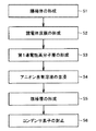
図2は、実施の形態1の固体電解コンデンサの製造方法の一例のフローチャートであり、図3(A)〜(D)は、実施の形態1の固体電解コンデンサの製造方法の一例について図解する模式的な断面図である。以下、図1〜図3を参照して、実施の形態1の固体電解コンデンサの製造方法の一例について説明する。
≪Method for manufacturing solid electrolytic capacitor≫
FIG. 2 is a flowchart of an example of the method for manufacturing the solid electrolytic capacitor according to the first embodiment, and FIGS. 3A to 3D are schematic diagrams illustrating an example of the method for manufacturing the solid electrolytic capacitor according to the first embodiment. FIG. Hereinafter, an example of the method for manufacturing the solid electrolytic capacitor of the first embodiment will be described with reference to FIGS.
(陽極体を形成する工程)
まず、図2のステップS1において、図3(A)に示すように、陽極体11を形成する。たとえば、金属粉末を準備し、棒状体の陽極リード12の長手方向の一端側を金属粉末に埋め込んだ状態で、当該粉末を所望の形状に成形する。次に、この成形体を焼結して、陽極リード12の一端が埋設された多孔質構造の陽極体11を形成する。
(Process for forming anode body)
First, in step S1 of FIG. 2, the
陽極体11の材料は特に限定されないが、誘電体被膜13の形成が容易である点からは、アルミニウム、タンタル、ニオブなどの弁作用金属を用いることが好ましい。また、陽極リード12の材料も特に限定されないが、陽極体11と同様の観点から、弁作用金属を用いることが好ましい。
The material of the
(誘電体被膜を形成する工程)
次に、図2のステップS2において、図3(B)に示すように、陽極体11の表面に誘電体被膜13を形成する。誘電体被膜13の形成方法は特に限定されない。たとえば、陽極体11が弁作用金属からなる場合には、陽極体11を化成処理することによって、陽極体11の表面に誘電体被膜13を形成することができる。化成処理としては、たとえば、陽極体11をリン酸水溶液または硝酸水溶液などの化成液に浸漬して熱処理してもよく、また、陽極体11を化成液に浸漬して電圧を印加してもよい。本工程により、陽極体11の表面を誘電体被膜13に変化させることができる。以上の工程により、表面に誘電体被膜13が設けられた陽極体11が準備される。
(Process for forming dielectric coating)
Next, in step S2 of FIG. 2, a
(第1導電性高分子層を形成する工程)
次に、図2のステップS3において、図3(C)に示すように、表面に誘電体被膜13が設けられた陽極体11上に、第1導電性高分子層14を形成する。第1導電性高分子層14は、化学重合法や電解重合法によって形成することができるが、誘電体被膜13上への形成が容易である点、および化学重合による導電性高分子層の構造が比較的粗く、後述するアニオン含有溶液の含浸が容易である点から、化学重合法によって形成することが好ましい。
(Step of forming the first conductive polymer layer)
Next, in step S3 of FIG. 2, as shown in FIG. 3C, the first
化学重合による第1導電性高分子層14の形成方法としては、たとえば、誘電体被膜13上に酸化剤およびドーパントを付着させた陽極体11を、第1導電性高分子層14を構成する高分子の前駆体モノマーを含むガスに曝露する方法がある。陽極体11に酸化剤およびドーパントを付着させる方法としては、たとえば、酸化剤およびドーパントを含む溶液に陽極体11を浸漬させる方法がある。また、酸化剤を含む溶液とドーパントを含む溶液のそれぞれに陽極体11を浸漬させてもよい。また、各溶液を陽極体11に塗布してもよい。
As a method for forming the first
上記の方法は、化学重合のうちの気相重合であるが、液相重合によって第1導電性高分子層14を形成してもよい。たとえば、誘電体被膜13が形成された陽極体11を、第1導電性高分子層14を構成する高分子の前駆体モノマー、酸化剤およびドーパントを含む溶液に浸漬して、誘電体被膜13上で前駆体モノマーを酸化重合させる方法がある。前駆体モノマー、酸化剤およびドーパントは1つの溶液に含まれる必要はなく、それぞれ別の溶液に含まれていてもよい。なお、2つ以上の溶液を用いて酸化重合を行う場合、各溶液への浸漬の順序は特に制限されるものではない。
The above method is gas phase polymerization of chemical polymerization, but the first
前駆体モノマーは、重合することによって、ポリチオフェンおよびその誘導体、ポリピロールおよびその誘導体、ポリアニリンおよびその誘導体、ならびにポリフランおよびその誘導体のいずれかとなる化合物である。たとえば、前駆体モノマーとして、3,4−エチレンジオキシチオフェン、3−アルキルチオフェン、N−メチルピロール、N,N−ジメチルアニリン、N−アルキルアニリンなどを用いることができる。 The precursor monomer is a compound that becomes one of polythiophene and derivatives thereof, polypyrrole and derivatives thereof, polyaniline and derivatives thereof, and polyfuran and derivatives thereof by polymerization. For example, 3,4-ethylenedioxythiophene, 3-alkylthiophene, N-methylpyrrole, N, N-dimethylaniline, N-alkylaniline and the like can be used as the precursor monomer.
酸化剤は、前駆体モノマーを重合させることができればよく、たとえば、硫酸、過酸化水素、鉄(III)、銅(II)、クロム(VI)、セリウム(IV)、マンガン(VII)、亜鉛(II)などを用いることができる。特に、これらの金属と塩を構成した芳香族スルホン酸金属塩は、酸化剤としての機能に加え、ドーパントとしての機能を有するため、好適に用いることができる。芳香族スルホン酸金属塩としては、たとえば、ナフタレンスルホン酸金属塩、テトラリンスルホン酸金属塩、アルキルベンゼンスルホン酸金属塩およびアルコキシベンゼンスルホン酸金属塩を用いることができる。 The oxidizing agent only needs to be able to polymerize the precursor monomer. For example, sulfuric acid, hydrogen peroxide, iron (III), copper (II), chromium (VI), cerium (IV), manganese (VII), zinc ( II) and the like can be used. In particular, an aromatic sulfonic acid metal salt that constitutes a salt with these metals has a function as a dopant in addition to a function as an oxidizing agent, and therefore can be suitably used. As the aromatic sulfonic acid metal salt, for example, naphthalene sulfonic acid metal salt, tetralin sulfonic acid metal salt, alkylbenzene sulfonic acid metal salt and alkoxybenzene sulfonic acid metal salt can be used.
ドーパントとしては、たとえば、アルキルスルホン酸、芳香族スルホン酸、多環芳香族スルホン酸などのスルホン酸化合物の酸または塩、硫酸、硝酸などを挙げることができる。また、酸化剤の機能とドーパントの機能とを有する芳香族スルホン酸金属塩を用いることができることは上述の通りである。 Examples of the dopant include acids or salts of sulfonic acid compounds such as alkylsulfonic acid, aromatic sulfonic acid, and polycyclic aromatic sulfonic acid, sulfuric acid, nitric acid, and the like. In addition, as described above, an aromatic sulfonic acid metal salt having an oxidizing agent function and a dopant function can be used.
(アニオン含有溶液を含浸させる工程)
次に、図2のステップS4において、第1導電性高分子層14にアニオン含有溶液を含浸させる。第1導電性高分子層14にアニオン含有溶液を含浸させる方法は特に限定されず、たとえば、第1導電性高分子層14が形成された陽極体11を、アニオン含有溶液に浸漬する方法がある。
(Step of impregnating the anion-containing solution)
Next, in step S4 of FIG. 2, the first
アニオン含有溶液は、上述したPfアニオンが上述した高沸点有機溶媒に溶解したものである。アニオン含有溶液は、たとえば、高沸点有機溶媒に、Pfアニオンとカチオンから構成される塩を添加することによって調製することができる。カチオンとしては、特に限定されず、たとえば、リチウム、ナトリウム、カリウム、ルビジウム、セシウム、フランシウム、アンモニア、またはテトラメチルアンモニウムやテトラエチルアンモニウムなどのアルキルアンモニウムなどのイオンを用いることができる。なお、Pfアニオンとカチオンとから構成される塩は、常温(25℃程度)で固体状態となる。 The anion-containing solution is a solution in which the Pf anion described above is dissolved in the high-boiling organic solvent described above. The anion-containing solution can be prepared, for example, by adding a salt composed of a Pf anion and a cation to a high boiling point organic solvent. The cation is not particularly limited, and for example, ions such as lithium, sodium, potassium, rubidium, cesium, francium, ammonia, or alkylammonium such as tetramethylammonium and tetraethylammonium can be used. In addition, the salt comprised from a Pf anion and a cation will be in a solid state at normal temperature (about 25 degreeC).
アニオン含有溶液中における塩の濃度、すなわち、Pfアニオンの濃度は1%以上が好ましく、この場合、第1導電性高分子層14中に浸透したPfアニオンによる誘電体被膜13の修復機能を効率的に発揮することができる。また、同Pfアニオンの濃度は、5%以上25%以下であることが好ましい。この場合、Pfアニオンを効率的に第1導電性高分子層14中に存在させることができる。また、アニオン含有溶液の粘度を十分に低く保つことができるため、第1導電性高分子層14中への浸透性がよく、また、第1導電性高分子層14中での移動度も高い。
The concentration of the salt in the anion-containing solution, that is, the concentration of Pf anion is preferably 1% or more. In this case, the repair function of the
なお、浸漬時間は1分以上であれば十分に第1導電性高分子層14中にアニオン含有溶液を浸透させることができる。また、製造タクトの観点からは、浸漬時間は60分以下であることが好ましい。より好ましくは、5分以上10分以下の場合に、浸透性、製造タクトをより適切に設計することができる。
If the immersion time is 1 minute or longer, the anion-containing solution can be sufficiently infiltrated into the first
(陰極層を形成する工程)
次に、図2のステップS5において、図3(D)に示すように、第1導電性高分子層14上に、カーボン層15および銀ペイント層16を形成する。
(Step of forming the cathode layer)
Next, in step S5 of FIG. 2, as shown in FIG. 3D, the
カーボン層15および銀ペイント層16のそれぞれの形成方法は特に限定されない。たとえば、カーボン層15は、第1導電性高分子層14が形成された陽極体11をカーボン粒子を分散させた溶液に浸漬し、その後乾燥処理することによって形成することができる。また、銀ペイント層16は、たとえば、カーボン層15を形成後、該陽極体11を銀粒子を含む溶液へ浸漬して乾燥処理することによって形成することができる。以上の工程により、コンデンサ素子10が作製される。
The formation method of the
(コンデンサ素子を封止する工程)
次に、図2のステップS6において、図1に示すように、コンデンサ素子10を封止して、固体電解コンデンサを製造する。封止の方法としては、特に限定されないが、たとえば、以下の方法がある。
(Process of sealing the capacitor element)
Next, in step S6 of FIG. 2, as shown in FIG. 1, the
すなわち、まず、陽極端子17を陽極リード12の露出している一端に接続し、銀ペイント層16上に接着層18を形成して陰極端子19の一端を接続する。次に、陽極端子17および陰極端子19の各他端が露出するように、コンデンサ素子10を外装樹脂20によって封止する。最後に、露出している陽極端子17および陰極端子19を外装樹脂20に沿うように折り曲げてエージング処理することにより、図1に示す固体電解コンデンサが製造される。
That is, first, the
上述の実施の形態1の固体電解コンデンサの製造方法によれば、第1導電性高分子層14中にPfアニオンと有機溶媒とが含まれる固体電解コンデンサを製造することができる。第1導電性高分子層14中にPfアニオンと有機溶媒とが含まれることにより、Pfアニオンが第1導電性高分子層14中に安定的に存在することができ、また、第1導電性高分子層14中を容易に移動することができる。
According to the method for manufacturing the solid electrolytic capacitor of the first embodiment described above, a solid electrolytic capacitor in which the Pf anion and the organic solvent are contained in the first
したがって、実施の形態1の固体電解コンデンサの製造方法によれば、Pfアニオンによる誘電体被膜13の効率的な修復が可能となり、また、ESRを低く保つことができる固体電解コンデンサを製造することができる。また、実施の形態1の固体電解コンデンサによれば、誘電体被膜13の損傷をPfアニオンによって効率的に修復することができ、また、Pfアニオンが導電性を有するために、ESRの低下を抑制することができる。すなわち、高性能な固体電解コンデンサを提供することができる。
Therefore, according to the method for manufacturing the solid electrolytic capacitor of the first embodiment, it is possible to efficiently repair the
また、第1導電性高分子層14中に存在する高沸点有機溶媒の安定性が高いため、たとえば、固体電解コンデンサをはんだ処理によって回路基板に実装した場合にも、Pfアニオンを安定的に第1導電性高分子層14中に存在させることができる。したがって、実施の形態1の固体電解コンデンサは、実装後においても、十分に高い性能を維持することができる。
In addition, since the high-boiling organic solvent present in the first
<実施の形態2>
≪固体電解コンデンサ≫
図4に、実施の形態2の固体電解コンデンサの模式的な断面図を示す。図4において、固体電解コンデンサは、陽極リード12が立設された陽極体11と、陽極体11の表面に設けられた誘電体被膜13と、誘電体被膜13上に設けられた第1導電性高分子層14と、第1導電性高分子層14上に設けられた第2導電性高分子層21とを備える。また、第2導電性高分子層21上には、カーボン層15および銀ペイント層16の順に積層された陰極層が設けられており、陽極体11、陽極リード12、誘電体被膜13、第1導電性高分子層14、第2導電性高分子層21、カーボン層15および銀ペイント層16によって、コンデンサ素子10が構成されている。
<Embodiment 2>
≪Solid electrolytic capacitor≫
FIG. 4 shows a schematic cross-sectional view of the solid electrolytic capacitor of the second embodiment. In FIG. 4, the solid electrolytic capacitor includes an
第2導電性高分子層21を構成する高分子は、第1導電性高分子層14と同様である。また、第2導電性高分子層21において、ドーパントが付与されている。ドーパントの種類は特に限定されず、たとえば、第1導電性高分子層14に付与可能なドーパントを用いることができる。なお、第2導電性高分子層21中にも、Pfアニオンおよび高沸点有機溶媒が含まれていてもよい。
The polymer constituting the second
本実施の形態2の固体電解コンデンサにおいて、上記以外の説明は、実施の形態1と同様であるため、その説明は繰り返さない。 In the solid electrolytic capacitor according to the second embodiment, the description other than the above is the same as that of the first embodiment, and therefore the description thereof will not be repeated.
≪固体電解コンデンサの製造方法≫
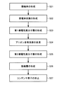
図5は、実施の形態2の固体電解コンデンサの製造方法の一例のフローチャートであり、図6(A)〜(E)は、実施の形態2の固体電解コンデンサの製造方法の一例について図解する模式的な断面図である。以下、図4〜図6を参照して、実施の形態2の固体電解コンデンサの製造方法の一例について説明する。
≪Method for manufacturing solid electrolytic capacitor≫
FIG. 5 is a flowchart of an example of the method for manufacturing the solid electrolytic capacitor of the second embodiment. FIGS. 6A to 6E are schematic diagrams illustrating an example of the method for manufacturing the solid electrolytic capacitor of the second embodiment. FIG. Hereinafter, an example of a method for manufacturing the solid electrolytic capacitor of the second embodiment will be described with reference to FIGS.
(陽極体を形成する工程)
まず、図5のステップS21において、図6(A)に示すように、陽極体11を形成する。陽極体11の形成方法は、実施の形態1と同様であるため、その説明は繰り返さない。
(Process for forming anode body)
First, in step S21 of FIG. 5, the
(誘電体被膜を形成する工程)
次に、図5のステップS22において、図6(B)に示すように、陽極体11の表面に誘電体被膜13を形成する。誘電体被膜13の形成方法は、実施の形態1と同様であるため、その説明は繰り返さない。以上の工程により、表面に誘電体被膜13が設けられた陽極体11が準備される。
(Process for forming dielectric coating)
Next, in step S <b> 22 of FIG. 5, as shown in FIG. 6B, a
(第1導電性高分子層を形成する工程)
次に、図5のステップS23において、図6(C)に示すように、表面に誘電体被膜13が設けられた陽極体11上に、第1導電性高分子層14を形成する。第1導電性高分子層14の形成方法は、実施の形態1と同様であるため、その説明は繰り返さない。
(Step of forming the first conductive polymer layer)
Next, in step S23 of FIG. 5, as shown in FIG. 6C, the first
(アニオン含有溶液を含浸させる工程)
次に、図5のステップS24において、第1導電性高分子層14にアニオン含有溶液を含浸させる。アニオン含有溶液の含浸方法は実施の形態1と同様であるため、その説明は繰り返さない。
(Step of impregnating the anion-containing solution)
Next, in step S24 of FIG. 5, the first
(第2導電性高分子層を形成する工程)
次に、図5のステップS25において、図6(D)に示すように、第1導電性高分子層14上に第2導電性高分子層21を形成する。第2導電性高分子層21は、化学重合法や電解重合法によって形成することができるが、電解重合法によって形成することが好ましい。その理由は以下の通りである。
(Step of forming the second conductive polymer layer)
Next, in step S <b> 25 of FIG. 5, the second
すなわち、電解重合法によって形成される導電性高分子層の構造は、化学重合法によって形成される導電性高分子層の構造よりも密である。このため、第2導電性高分子層21を電解重合法によって形成した場合、第1導電性高分子層14中に含まれるアニオン含有溶液が、電解重合法によって形成された第2導電性高分子層21中に移動し難い傾向となる。これにより、誘電体被膜13近傍に位置する第1導電性高分子層14中にアニオン含有溶液を留めることができるため、Pfアニオンによる誘電体被膜13の修復機能をより効果的に発揮することができる。
That is, the structure of the conductive polymer layer formed by the electrolytic polymerization method is denser than the structure of the conductive polymer layer formed by the chemical polymerization method. Therefore, when the second
電解重合による第2導電性高分子層21の形成方法としては、たとえば、陽極体11を第2導電性高分子層21の前駆体モノマーおよびドーパントを含む電解液に浸漬し、この電解液に電流を流すことによって、第1導電性高分子層14上に第2導電性高分子層21を形成させる方法がある。
As a method for forming the second
(陰極層を形成する工程)
次に、図5のステップS26において、図6(E)に示すように、第2導電性高分子層21上に、カーボン層15および銀ペイント層16を形成する。陰極層の形成方法は、実施の形態1と同様であるため、その説明は繰り返さない。
(Step of forming the cathode layer)
Next, in step S <b> 26 of FIG. 5, as shown in FIG. 6E, the
(コンデンサ素子を封止する工程)
次に、図5のステップS27において、図4に示すように、コンデンサ素子10を封止して、固体電解コンデンサを製造する。コンデンサ素子10の封止方法は、実施の形態1と同様であるため、その説明は繰り返さない。
(Process of sealing the capacitor element)
Next, in step S27 of FIG. 5, as shown in FIG. 4, the
上述の実施の形態2の固体電解コンデンサの製造方法によれば、第1導電性高分子層14中にPfアニオンと有機溶媒とが含まれる固体電解コンデンサを製造することができる。第1導電性高分子層14中にPfアニオンと有機溶媒とが含まれることにより、Pfアニオンが第1導電性高分子層14中に安定的に存在することができ、また、第1導電性高分子層14中を容易に移動することができる。
According to the method for manufacturing the solid electrolytic capacitor of the second embodiment described above, a solid electrolytic capacitor in which the Pf anion and the organic solvent are contained in the first
したがって、実施の形態2の固体電解コンデンサの製造方法によれば、Pfアニオンによる誘電体被膜13の効率的な修復が可能となり、また、ESRを低く保つことができる固体電解コンデンサを製造することができる。また、実施の形態2の固体電解コンデンサによれば、誘電体被膜13の損傷をPfアニオンによって効率的に修復することができ、また、Pfアニオンが導電性を有するために、ESRの低下を抑制することができる。すなわち、高性能な固体電解コンデンサを提供することができる。
Therefore, according to the method for manufacturing the solid electrolytic capacitor of the second embodiment, it is possible to efficiently repair the
また、実施の形態2の固体電解コンデンサの製造方法において、第1導電性高分子層14を化学重合法によって形成し、第2導電性高分子層21を電解重合法によって形成することが好ましい。これにより、比較的疎な構造の第1導電性高分子層14と、比較的密な構造の第2導電性高分子層21を有する固体電解コンデンサを作製することができる。
In the method for manufacturing the solid electrolytic capacitor according to the second embodiment, it is preferable that the first
この場合、第1導電性高分子層14中に含浸されたアニオン含有溶液が第2導電性高分子層21に移動するのを、その構造の違いにより抑制することができるため、アニオン含有溶液を、より誘電体被膜13に近い位置にある第1導電性高分子層14中に留めることができる。したがって、Pfアニオンによる誘電体被膜13の修復機能をより効率的に発揮させることができる。
In this case, the anion-containing solution impregnated in the first
また、第1導電性高分子層14中に存在する高沸点有機溶媒の安定性が高いため、たとえば、固体電解コンデンサをはんだ処理によって回路基板に実装した場合にも、Pfアニオンを安定的に第1導電性高分子層14中に存在させることができる。したがって、実施の形態2の固体電解コンデンサは、実装後においても、十分に高い性能を維持することができる。
In addition, since the high-boiling organic solvent present in the first
本発明における固体電解コンデンサは、上記の実施の形態1および2に係る固体電解コンデンサに限定されず、公知の形状に応用することができる。公知の形状としては具体的に、巻回型の固体電解コンデンサ、弁金属の板を用いた積層型の固体電解コンデンサなどがある。 The solid electrolytic capacitor in the present invention is not limited to the solid electrolytic capacitor according to the first and second embodiments, and can be applied to a known shape. Specific examples of the known shape include a wound solid electrolytic capacitor and a laminated solid electrolytic capacitor using a valve metal plate.
特に、焼結体からなる陽極体上に形成された導電性高分子層は、アニオン含有溶液を保持する能力に優れているため、焼結体からなる陽極体を有する固体電解コンデンサに、本発明をより好適に適用することができる。 In particular, since the conductive polymer layer formed on the anode body made of a sintered body is excellent in the ability to hold an anion-containing solution, the present invention is applied to a solid electrolytic capacitor having an anode body made of a sintered body. Can be applied more suitably.
以下、実施例を挙げて本発明をより詳細に説明するが、本発明はこれらに限定されるものではない。 EXAMPLES Hereinafter, although an Example is given and this invention is demonstrated in detail, this invention is not limited to these.
<実施例1>
本実施例において、図4に示す構造の固体電解コンデンサを作製した。以下に、固体電解コンデンサの具体的な製造方法について説明する。
<Example 1>
In this example, a solid electrolytic capacitor having the structure shown in FIG. 4 was produced. Below, the specific manufacturing method of a solid electrolytic capacitor is demonstrated.
(陽極体の形成)
まず、タンタル粉末を準備し、棒状体のタンタルからなる陽極リードの長手方向の一端側を金属粉末に埋め込んだ状態で、タンタル粉末を直方体に成形した。そして、この成形体を焼結して、陽極リードの一端が埋設された多孔質構造の陽極体を形成した。このときの陽極体の寸法は、縦×横×高さが4.5mm×3.5mm×2.5mmであった。
(Formation of anode body)
First, tantalum powder was prepared, and the tantalum powder was formed into a rectangular parallelepiped in a state where one end side in the longitudinal direction of the anode lead made of tantalum of a rod-like body was embedded in the metal powder. The molded body was sintered to form a porous anode body in which one end of the anode lead was embedded. The dimensions of the anode body at this time were 4.5 mm × 3.5 mm × 2.5 mm in length × width × height.
(誘電体被膜の形成)
次に、陽極体をリン酸溶液に浸漬して、陽極リードを介して陽極体に30Vの電圧を印加することにより、陽極体の表面にTa2O5からなる誘電体被膜を形成した。
(Formation of dielectric coating)
Next, the anode body was immersed in a phosphoric acid solution, and a voltage of 30 V was applied to the anode body through the anode lead to form a dielectric film made of Ta 2 O 5 on the surface of the anode body.
(第1導電性高分子層の形成)
次に、化学重合法によって誘電体被膜上に第1導電性高分子層を形成した。具体的には、まず、ピロールを3mol/Lの濃度で含むエタノール溶液と、過硫酸アンモニウムおよびパラトルエンスルホン酸を含有する水溶液を準備した。そして、25℃に調整した上記エタノール溶液中に、誘電体被膜が形成された陽極体を5分間浸漬して、誘電体被膜に第1導電性高分子層の前駆体モノマーであるピロールを付着させた。その後、陽極体をエタノール溶液から引き上げて、引き続き、25℃に設定された上記水溶液に、5分間浸漬した。そして、陽極体を水溶液から引き上げて、10分間以上室温で放置することにより乾燥させた。この操作により、誘電体被膜上に第1導電性高分子層が形成された。
(Formation of first conductive polymer layer)
Next, a first conductive polymer layer was formed on the dielectric film by chemical polymerization. Specifically, first, an ethanol solution containing pyrrole at a concentration of 3 mol / L and an aqueous solution containing ammonium persulfate and paratoluenesulfonic acid were prepared. Then, the anode body on which the dielectric film is formed is immersed in the ethanol solution adjusted to 25 ° C. for 5 minutes, and pyrrole, which is the precursor monomer of the first conductive polymer layer, is attached to the dielectric film. It was. Thereafter, the anode body was pulled up from the ethanol solution and subsequently immersed in the aqueous solution set at 25 ° C. for 5 minutes. Then, the anode body was pulled up from the aqueous solution and allowed to stand at room temperature for 10 minutes or more to dry. By this operation, the first conductive polymer layer was formed on the dielectric film.
(アニオン含有溶液の含浸)
次に、第1導電性高分子層にアニオン含有溶液を含浸させた。具体的には、まず、Pfアニオンを含む塩として、下記化学式(2)に示すビス(トリフルオロメタンスルホニル)イミドリチウム(以下、「TFSI」という。)を準備し、高沸点有機溶媒として、トリエチレングリコールブチルメチルエーテルを準備した。なお、TFSIは、ビス(トリフルオロメタンスルホニル)イミドアニオンと、リチウムカチオンとから構成される塩である。そして、トリエチレングリコールブチルメチルエーテルに、濃度が1%となるようにTFSIを添加し、アニオン含有溶液を準備した。
(Impregnation of anion-containing solution)
Next, the first conductive polymer layer was impregnated with an anion-containing solution. Specifically, first, bis (trifluoromethanesulfonyl) imide lithium (hereinafter referred to as “TFSI”) represented by the following chemical formula (2) is prepared as a salt containing Pf anion, and triethylene is used as a high boiling point organic solvent. Glycol butyl methyl ether was prepared. TFSI is a salt composed of a bis (trifluoromethanesulfonyl) imide anion and a lithium cation. And TFSI was added to triethylene glycol butyl methyl ether so that a density | concentration might be 1%, and the anion containing solution was prepared.
そして、アニオン含有溶液に第1導電性高分子層が形成された陽極体を5分間浸漬し、その後、陽極体をアニオン含有溶液から引上げて室温で放置した。 And the anode body in which the 1st electroconductive polymer layer was formed in the anion containing solution was immersed for 5 minutes, Then, the anode body was pulled up from the anion containing solution, and was left to stand at room temperature.
(第2導電性高分子層の形成)
次に、電解重合法によって、第1導電性高分子層上に第2導電性高分子層を形成した。具体的には、まず、電解液として、ピロールおよびアルキルナフタレンスルホン酸を含む水溶液を準備した。そして、該水溶液を電解重合用装置の電解槽内に満たし、その水溶液に陽極体を浸漬して、第1導電性高分子層に0.5mAの電流を3時間通電した。この操作により、第1導電性高分子層上に第2導電性高分子層が形成された。
(Formation of second conductive polymer layer)
Next, a second conductive polymer layer was formed on the first conductive polymer layer by electrolytic polymerization. Specifically, first, an aqueous solution containing pyrrole and alkylnaphthalenesulfonic acid was prepared as an electrolytic solution. Then, the aqueous solution was filled in an electrolytic tank of an apparatus for electrolytic polymerization, an anode body was immersed in the aqueous solution, and a current of 0.5 mA was passed through the first conductive polymer layer for 3 hours. By this operation, the second conductive polymer layer was formed on the first conductive polymer layer.
(陰極層の形成)
上記操作の終了後、水溶液から陽極体を引き上げ、これを水で洗浄後、100℃の乾燥器内に配置して、10分間乾燥させた。そして、乾燥後の陽極体に、グラファイト粒子懸濁液を塗布して大気中で乾燥させることによりカーボン層を形成し、さらに、銀粒子を含む溶液を用いて銀ペースト層を形成した。以上の操作により、コンデンサ素子が作製された。
(Formation of cathode layer)
After completion of the above operation, the anode body was pulled up from the aqueous solution, washed with water, then placed in a dryer at 100 ° C. and dried for 10 minutes. And the carbon layer was formed by apply | coating a graphite particle suspension to the anode body after drying, and making it dry in air | atmosphere, Furthermore, the silver paste layer was formed using the solution containing silver particle. The capacitor element was produced by the above operation.
(コンデンサ素子の封止)
そして、コンデンサ素子において、陽極リードに銅からなる陽極端子を溶接し、銀ペースト層に銀接着剤を塗布して接着層を形成し、接着層に銅からなる陰極端子の一端を接着させた。さらに、陽極端子および陰極端子の一部が露出するように、コンデンサ素子を外装樹脂で封止した。露出する陽極端子および陰極端子を外装樹脂に沿うように折り曲げた後、エージング処理を行った。
(Capacitor element sealing)
In the capacitor element, an anode terminal made of copper was welded to the anode lead, a silver adhesive was applied to the silver paste layer to form an adhesive layer, and one end of the cathode terminal made of copper was bonded to the adhesive layer. Further, the capacitor element was sealed with an exterior resin so that part of the anode terminal and the cathode terminal was exposed. After the exposed anode terminal and cathode terminal were bent along the exterior resin, an aging treatment was performed.
製造された固体電解コンデンサの定格電圧は10V、定格容量は330μFであり、縦×横×高さが7.3mm×4.3mm×3.8mmであった。 The manufactured solid electrolytic capacitor had a rated voltage of 10 V, a rated capacity of 330 μF, and a length × width × height of 7.3 mm × 4.3 mm × 3.8 mm.
<実施例2>
アニオン含有溶液中のTFSIの濃度を5%とした以外は、実施例1と同様の方法により、固体電解コンデンサを製造した。なお、製造された固体電解コンデンサの定格電圧、定格容量、外形は実施例1の固体電解コンデンサと同様であった。
<Example 2>
A solid electrolytic capacitor was produced in the same manner as in Example 1 except that the concentration of TFSI in the anion-containing solution was 5%. The manufactured solid electrolytic capacitor had the same rated voltage, rated capacity, and outer shape as the solid electrolytic capacitor of Example 1.
<実施例3>
アニオン含有溶液中のTFSIの濃度を10%とした以外は、実施例1と同様の方法により、固体電解コンデンサを製造した。なお、製造された固体電解コンデンサの定格電圧、定格容量、外形は実施例1の固体電解コンデンサと同様であった。
<Example 3>
A solid electrolytic capacitor was produced in the same manner as in Example 1 except that the concentration of TFSI in the anion-containing solution was 10%. The manufactured solid electrolytic capacitor had the same rated voltage, rated capacity, and outer shape as the solid electrolytic capacitor of Example 1.
<実施例4>
アニオン含有溶液中のTFSIの濃度を20%とした以外は、実施例1と同様の方法により、固体電解コンデンサを製造した。なお、製造された固体電解コンデンサの定格電圧、定格容量、外形は実施例1の固体電解コンデンサと同様であった。
<Example 4>
A solid electrolytic capacitor was produced in the same manner as in Example 1 except that the concentration of TFSI in the anion-containing solution was 20%. The manufactured solid electrolytic capacitor had the same rated voltage, rated capacity, and outer shape as the solid electrolytic capacitor of Example 1.
<実施例5>
アニオン含有溶液中のTFSIを飽和させた以外は、実施例1と同様の方法により、固体電解コンデンサを製造した。なお、製造された固体電解コンデンサの定格電圧、定格容量、外形は実施例1の固体電解コンデンサと同様であった。
<Example 5>
A solid electrolytic capacitor was produced in the same manner as in Example 1 except that TFSI in the anion-containing solution was saturated. The manufactured solid electrolytic capacitor had the same rated voltage, rated capacity, and outer shape as the solid electrolytic capacitor of Example 1.
<実施例6>
アニオン含有溶液に用いる高沸点有機溶媒を、プロピレンカーボネートとし、TFSIの濃度を10%とした以外は、実施例1と同様の方法により、固体電解コンデンサを製造した。なお、製造された固体電解コンデンサの定格電圧、定格容量、外形は実施例1の固体電解コンデンサと同様であった。
<Example 6>
A solid electrolytic capacitor was produced in the same manner as in Example 1 except that propylene carbonate was used as the high-boiling organic solvent used in the anion-containing solution and the TFSI concentration was 10%. The manufactured solid electrolytic capacitor had the same rated voltage, rated capacity, and outer shape as the solid electrolytic capacitor of Example 1.
<実施例7>
アニオン含有溶液に用いる高沸点有機溶媒を、ポリエチレングリコールジメチルエーテルとし、TFSIの濃度を10%とした以外は、実施例1と同様の方法により、固体電解コンデンサを製造した。なお、製造された固体電解コンデンサの定格電圧、定格容量、外形は実施例1の固体電解コンデンサと同様であった。
<Example 7>
A solid electrolytic capacitor was produced in the same manner as in Example 1, except that the high-boiling organic solvent used in the anion-containing solution was polyethylene glycol dimethyl ether and the TFSI concentration was 10%. The manufactured solid electrolytic capacitor had the same rated voltage, rated capacity, and outer shape as the solid electrolytic capacitor of Example 1.
<実施例8>
アニオン含有溶液に用いる高沸点有機溶媒を、チオジエタノールとし、TFSIの濃度を10%とした以外は、実施例1と同様の方法により、固体電解コンデンサを製造した。なお、製造された固体電解コンデンサの定格電圧、定格容量、外形は実施例1の固体電解コンデンサと同様であった。
<Example 8>
A solid electrolytic capacitor was produced in the same manner as in Example 1 except that the high-boiling organic solvent used in the anion-containing solution was thiodiethanol and the TFSI concentration was 10%. The manufactured solid electrolytic capacitor had the same rated voltage, rated capacity, and outer shape as the solid electrolytic capacitor of Example 1.
<比較例1>
アニオン含有溶液を含浸させる工程を行なわなかった以外は、実施例1と同様の方法により、固体電解コンデンサを製造した。なお、製造された固体電解コンデンサの定格電圧、定格容量、外形は実施例1の固体電解コンデンサと同様であった。
<Comparative Example 1>
A solid electrolytic capacitor was produced in the same manner as in Example 1 except that the step of impregnating the anion-containing solution was not performed. The manufactured solid electrolytic capacitor had the same rated voltage, rated capacity, and outer shape as the solid electrolytic capacitor of Example 1.
<比較例2>
アニオン含有溶液において、高沸点有機溶媒の代わりに、プロピレングリコールモノメチルエーテル(沸点:120℃)を用い、TFSIの濃度を10%とした以外は、実施例1と同様の方法により、固体電解コンデンサを製造した。なお、製造された固体電解コンデンサの定格電圧、定格容量、外形は実施例1の固体電解コンデンサと同様であった。
<Comparative example 2>
In the anion-containing solution, a solid electrolytic capacitor was prepared in the same manner as in Example 1 except that propylene glycol monomethyl ether (boiling point: 120 ° C.) was used instead of the high boiling point organic solvent and the TFSI concentration was 10%. Manufactured. The manufactured solid electrolytic capacitor had the same rated voltage, rated capacity, and outer shape as the solid electrolytic capacitor of Example 1.
<比較例3>
TSFIの代わりに、NaClを用い、NaClの濃度を10%とした以外は、実施例1と同様の方法により、固体電解コンデンサを製造した。なお、製造された固体電解コンデンサの定格電圧、定格容量、外形は実施例1の固体電解コンデンサと同様であった。
<Comparative Example 3>
A solid electrolytic capacitor was manufactured in the same manner as in Example 1 except that NaCl was used instead of TSFI and the NaCl concentration was 10%. The manufactured solid electrolytic capacitor had the same rated voltage, rated capacity, and outer shape as the solid electrolytic capacitor of Example 1.
<性能評価>
≪ESRの測定≫
各実施例1〜8および各比較例1〜3の固体電解コンデンサからそれぞれランダムに20個ずつ抽出した。抽出された各固体電解コンデンサについて、4端子測定用のLCRメータを用いて周波数100kHzにおける各固体電解コンデンサのESR(mΩ)を測定し、各実施例1〜8および各比較例1〜3における平均値を算出した。この結果を表1の「ESR(mΩ)」に示した。
<Performance evaluation>
≪Measurement of ESR≫
Twenty pieces were randomly extracted from each of the solid electrolytic capacitors of Examples 1 to 8 and Comparative Examples 1 to 3. For each extracted solid electrolytic capacitor, the ESR (mΩ) of each solid electrolytic capacitor at a frequency of 100 kHz was measured using an LCR meter for 4-terminal measurement, and the average in each of Examples 1 to 8 and Comparative Examples 1 to 3 The value was calculated. The results are shown in “ESR (mΩ)” in Table 1.
≪耐電圧試験≫
各実施例1〜8および各比較例1〜3の固体電解コンデンサからそれぞれランダムに20個ずつ抽出した。抽出された各固体電解コンデンサについて、印加する直流電圧を1V/秒の速度で上昇させて、耐電圧試験を行った。漏れ電流が1mA以上となったときの電圧を耐電圧とし、各実施例1〜8および各比較例1〜3の固体電解コンデンサにおける平均値を算出した。この結果を表1の「耐電圧(V)」に示した。
≪Withstand voltage test≫
Twenty pieces were randomly extracted from each of the solid electrolytic capacitors of Examples 1 to 8 and Comparative Examples 1 to 3. With respect to each extracted solid electrolytic capacitor, the applied DC voltage was increased at a rate of 1 V / sec, and a withstand voltage test was performed. The voltage when the leakage current was 1 mA or more was taken as the withstand voltage, and the average value in the solid electrolytic capacitors of Examples 1 to 8 and Comparative Examples 1 to 3 was calculated. The results are shown in “Withstand voltage (V)” of Table 1.
≪サージ耐圧試験≫
各実施例1〜8および各比較例1〜3の固体電解コンデンサからそれぞれランダムに20個ずつ抽出した。抽出された固体電解コンデンサについて、最高使用温度である105℃環境下で、サージ耐圧試験を行った。具体的には、各固体電解コンデンサに1kΩの放電用抵抗を接続した上で、固体電解コンデンサについて、5分30秒間放電後、30秒間充電するという合計6分間のサイクルを1000回繰り返した。この試験の終了後、各固体電解コンデンサにおける漏れ電流を測定し、漏れ電流が1mA以上の場合に故障と判断してその数を調べた。この結果を表1の「故障数(個)」に示した。
≪Surge withstand voltage test≫
Twenty pieces were randomly extracted from each of the solid electrolytic capacitors of Examples 1 to 8 and Comparative Examples 1 to 3. The extracted solid electrolytic capacitor was subjected to a surge withstand voltage test in an environment of 105 ° C. which is the maximum use temperature. Specifically, after connecting a discharging resistor of 1 kΩ to each solid electrolytic capacitor, the solid electrolytic capacitor was discharged for 5 minutes and 30 seconds and then charged for 30 seconds, and the cycle of 6 minutes in total was repeated 1000 times. After the end of this test, the leakage current in each solid electrolytic capacitor was measured, and when the leakage current was 1 mA or more, it was judged as a failure and the number was examined. The results are shown in “Number of failures (pieces)” in Table 1.
表1を参照して、アニオン含有溶液の含浸を行なわなかった比較例1のESRに対し、TFSIを含むアニオン含有溶液の含浸を行なった実施例1〜8のESRは同じ、またはわずかしか上昇しておらず、低く抑えられることが分かった。特に、アニオン含有溶液中のTFSIの濃度が20%以下の場合、ESRは十分に低く抑えられることがわかった。また、実施例1〜8において、高沸点溶媒の種類を変えた場合であっても、ESRの増加を抑制する効果は同様であることがわかった。 Referring to Table 1, the ESR of Examples 1 to 8 in which the anion-containing solution containing TFSI was impregnated was the same or slightly increased compared to the ESR of Comparative Example 1 in which the anion-containing solution was not impregnated. It was not found and it was found to be low. In particular, it was found that when the concentration of TFSI in the anion-containing solution is 20% or less, the ESR is sufficiently low. Moreover, in Examples 1-8, even if it was a case where the kind of high boiling point solvent was changed, it turned out that the effect which suppresses the increase in ESR is the same.
また、比較例1〜3の耐電圧に対し、実施例1〜8の耐電圧は高かった。特に、アニオン含有溶液中のTFSIの濃度が5%以上の場合耐電圧はより高かった。また、さらに、サージ耐圧試験後においても、実施例1で20個のうち2つの故障がみられたものの、比較例1〜3と比較して故障数は少なく、また、実施例2〜8では、故障数は0であった。 Moreover, the withstand voltage of Examples 1-8 was high with respect to the withstand voltage of Comparative Examples 1-3. In particular, the withstand voltage was higher when the concentration of TFSI in the anion-containing solution was 5% or more. Furthermore, even after the surge withstand voltage test, although two failures out of 20 were found in Example 1, the number of failures was small compared to Comparative Examples 1-3, and in Examples 2-8 The number of failures was zero.
今回開示された実施の形態および実施例はすべての点で例示であって制限的なものではないと考えられるべきである。本発明の範囲は上記した説明ではなくて特許請求の範囲によって示され、特許請求の範囲と均等の意味および範囲内でのすべての変更が含まれることが意図される。 It should be understood that the embodiments and examples disclosed herein are illustrative and non-restrictive in every respect. The scope of the present invention is defined by the terms of the claims, rather than the description above, and is intended to include any modifications within the scope and meaning equivalent to the terms of the claims.
本発明は、固体電解コンデンサ、特に、導電性高分子層を有する固体電解コンデンサに広く利用することができる。 The present invention can be widely used for solid electrolytic capacitors, particularly solid electrolytic capacitors having a conductive polymer layer.
10 コンデンサ素子、11 陽極体、12 陽極リード、13 誘電体被膜、14 第1導電性高分子層、15 カーボン層、16 銀ペイント層、17 陽極端子、18 接着層、19 陰極端子、20 外層樹脂、21 第2導電性高分子層。
DESCRIPTION OF
Claims (11)
前記陽極体の表面に設けられた誘電体被膜と、
前記陽極体上に設けられた第1導電性高分子層と、を備え、
前記第1導電性高分子層中には、下記化学式(1)で表されるアニオンと、沸点が240℃以上の有機溶媒とが含まれている、固体電解コンデンサ。
A dielectric coating provided on the surface of the anode body;
A first conductive polymer layer provided on the anode body,
A solid electrolytic capacitor in which the first conductive polymer layer contains an anion represented by the following chemical formula (1) and an organic solvent having a boiling point of 240 ° C. or higher.
前記第1導電性高分子層に、アニオン含有溶液を含浸させる工程と、を含み、
前記アニオン含有溶液は、沸点が240℃以上の有機溶媒に、下記化学式(1)で表されるアニオンが溶解された溶液である、固体電解コンデンサの製造方法。
Impregnating the first conductive polymer layer with an anion-containing solution,
The said anion containing solution is a manufacturing method of a solid electrolytic capacitor which is a solution by which the anion represented by following Chemical formula (1) was melt | dissolved in the organic solvent whose boiling point is 240 degreeC or more.
Priority Applications (3)
| Application Number | Priority Date | Filing Date | Title |
|---|---|---|---|
| JP2011005073A JP2012146867A (en) | 2011-01-13 | 2011-01-13 | Solid electrolytic capacitor and method for manufacturing the same |
| US13/339,729 US8971021B2 (en) | 2011-01-13 | 2011-12-29 | Solid electrolytic capacitor and method for manufacturing the same |
| CN201210004353.XA CN102592847B (en) | 2011-01-13 | 2012-01-09 | Solid electrolytic capacitor And Manufacturing approach |
Applications Claiming Priority (1)
| Application Number | Priority Date | Filing Date | Title |
|---|---|---|---|
| JP2011005073A JP2012146867A (en) | 2011-01-13 | 2011-01-13 | Solid electrolytic capacitor and method for manufacturing the same |
Publications (1)
| Publication Number | Publication Date |
|---|---|
| JP2012146867A true JP2012146867A (en) | 2012-08-02 |
Family
ID=46481343
Family Applications (1)
| Application Number | Title | Priority Date | Filing Date |
|---|---|---|---|
| JP2011005073A Pending JP2012146867A (en) | 2011-01-13 | 2011-01-13 | Solid electrolytic capacitor and method for manufacturing the same |
Country Status (3)
| Country | Link |
|---|---|
| US (1) | US8971021B2 (en) |
| JP (1) | JP2012146867A (en) |
| CN (1) | CN102592847B (en) |
Cited By (1)
| Publication number | Priority date | Publication date | Assignee | Title |
|---|---|---|---|---|
| JP2015515746A (en) * | 2012-03-12 | 2015-05-28 | ヘレウス プレシャス メタルズ ゲーエムベーハー ウント コンパニー カーゲー | Addition of polymer to thiophene monomer in in situ polymerization |
Families Citing this family (3)
| Publication number | Priority date | Publication date | Assignee | Title |
|---|---|---|---|---|
| CN103065807A (en) * | 2013-01-11 | 2013-04-24 | 天津理工大学 | High-energy density super capacitor based on nanometer dielectric material layer |
| JP6796755B2 (en) * | 2015-02-04 | 2020-12-09 | パナソニックIpマネジメント株式会社 | Electrolytic capacitors and their manufacturing methods |
| CN113178333A (en) * | 2021-04-28 | 2021-07-27 | 中国振华(集团)新云电子元器件有限责任公司(国营第四三二六厂) | Silver paste dipping method for tantalum capacitor |
Citations (2)
| Publication number | Priority date | Publication date | Assignee | Title |
|---|---|---|---|---|
| JP2009054925A (en) * | 2007-08-29 | 2009-03-12 | Kaneka Corp | Manufacturing method of conductive polymer capacitor |
| JP2010157555A (en) * | 2008-12-26 | 2010-07-15 | Shin Etsu Polymer Co Ltd | Capacitor and method of manufacturing the same |
Family Cites Families (5)
| Publication number | Priority date | Publication date | Assignee | Title |
|---|---|---|---|---|
| CN100367415C (en) * | 2002-10-03 | 2008-02-06 | 大金工业株式会社 | Fluoropolymer solid electrolyte containing fluoroether chains |
| JP4927604B2 (en) | 2007-03-07 | 2012-05-09 | 株式会社カネカ | Method for producing conductive polymer solid electrolytic capacitor |
| JP4877820B2 (en) * | 2007-06-29 | 2012-02-15 | 三洋電機株式会社 | Solid electrolytic capacitor |
| JP5484995B2 (en) * | 2009-04-28 | 2014-05-07 | 三洋電機株式会社 | Solid electrolytic capacitor and manufacturing method thereof |
| JP5388811B2 (en) * | 2009-11-20 | 2014-01-15 | 三洋電機株式会社 | Solid electrolytic capacitor and manufacturing method thereof |
-
2011
- 2011-01-13 JP JP2011005073A patent/JP2012146867A/en active Pending
- 2011-12-29 US US13/339,729 patent/US8971021B2/en active Active
-
2012
- 2012-01-09 CN CN201210004353.XA patent/CN102592847B/en not_active Expired - Fee Related
Patent Citations (2)
| Publication number | Priority date | Publication date | Assignee | Title |
|---|---|---|---|---|
| JP2009054925A (en) * | 2007-08-29 | 2009-03-12 | Kaneka Corp | Manufacturing method of conductive polymer capacitor |
| JP2010157555A (en) * | 2008-12-26 | 2010-07-15 | Shin Etsu Polymer Co Ltd | Capacitor and method of manufacturing the same |
Cited By (1)
| Publication number | Priority date | Publication date | Assignee | Title |
|---|---|---|---|---|
| JP2015515746A (en) * | 2012-03-12 | 2015-05-28 | ヘレウス プレシャス メタルズ ゲーエムベーハー ウント コンパニー カーゲー | Addition of polymer to thiophene monomer in in situ polymerization |
Also Published As
| Publication number | Publication date |
|---|---|
| CN102592847B (en) | 2016-12-28 |
| US8971021B2 (en) | 2015-03-03 |
| CN102592847A (en) | 2012-07-18 |
| US20120182667A1 (en) | 2012-07-19 |
Similar Documents
| Publication | Publication Date | Title |
|---|---|---|
| US8654510B2 (en) | Solid electrolytic capacitor and method of manufacturing solid electrolytic capacitor | |
| TWI478189B (en) | Solid electrolytic capacitor and method of manufacturing thereof | |
| JP5575505B2 (en) | Solid electrolytic capacitor manufacturing method and solid electrolytic capacitor | |
| JP6740579B2 (en) | Solid electrolytic capacitor and method of manufacturing solid electrolytic capacitor | |
| CN104919555B (en) | Electrolytic capacitor and its manufacture method | |
| JP6142280B2 (en) | Solid electrolytic capacitor and manufacturing method thereof | |
| JP7599121B2 (en) | Electrolytic capacitor and its manufacturing method | |
| JPWO2015198547A1 (en) | Electrolytic capacitor manufacturing method | |
| US8971021B2 (en) | Solid electrolytic capacitor and method for manufacturing the same | |
| JP6383946B2 (en) | Solid electrolytic capacitor manufacturing method and solid electrolytic capacitor | |
| JP2011071178A (en) | Method of manufacturing solid electrolytic capacitor | |
| CN117063256A (en) | Electrolytic capacitor and manufacturing method thereof | |
| JP7115618B2 (en) | Solid electrolytic capacitor and method for manufacturing solid electrolytic capacitor | |
| JP2013074026A (en) | Solid electrolytic capacitor and method for manufacturing the same | |
| JP2009064960A (en) | Solid electrolytic capacitor and method of manufacturing the same | |
| JPWO2007074869A1 (en) | Solid electrolytic capacitor and manufacturing method thereof | |
| JP2007116028A (en) | Method for manufacturing solid electrolytic capacitor | |
| WO2006068302A1 (en) | Solid electrolytic capacitor element, solid electrolytic capacitor and method for manufacturing same | |
| JP2010080599A (en) | Method of manufacturing conductive polymer solid-state electrolytic capacitor |
Legal Events
| Date | Code | Title | Description |
|---|---|---|---|
| A621 | Written request for application examination |
Free format text: JAPANESE INTERMEDIATE CODE: A621 Effective date: 20131217 |
|
| A977 | Report on retrieval |
Free format text: JAPANESE INTERMEDIATE CODE: A971007 Effective date: 20140822 |
|
| A131 | Notification of reasons for refusal |
Free format text: JAPANESE INTERMEDIATE CODE: A131 Effective date: 20140826 |
|
| A521 | Written amendment |
Free format text: JAPANESE INTERMEDIATE CODE: A523 Effective date: 20140925 |
|
| A711 | Notification of change in applicant |
Free format text: JAPANESE INTERMEDIATE CODE: A711 Effective date: 20141107 |
|
| RD02 | Notification of acceptance of power of attorney |
Free format text: JAPANESE INTERMEDIATE CODE: A7422 Effective date: 20141203 |
|
| A02 | Decision of refusal |
Free format text: JAPANESE INTERMEDIATE CODE: A02 Effective date: 20150324 |