JP2012161122A - Power conversion device - Google Patents
Power conversion device Download PDFInfo
- Publication number
- JP2012161122A JP2012161122A JP2011017463A JP2011017463A JP2012161122A JP 2012161122 A JP2012161122 A JP 2012161122A JP 2011017463 A JP2011017463 A JP 2011017463A JP 2011017463 A JP2011017463 A JP 2011017463A JP 2012161122 A JP2012161122 A JP 2012161122A
- Authority
- JP
- Japan
- Prior art keywords
- bolt
- connector
- power
- double
- inner bolt
- Prior art date
- Legal status (The legal status is an assumption and is not a legal conclusion. Google has not performed a legal analysis and makes no representation as to the accuracy of the status listed.)
- Withdrawn
Links
Images


Classifications
-
- Y—GENERAL TAGGING OF NEW TECHNOLOGICAL DEVELOPMENTS; GENERAL TAGGING OF CROSS-SECTIONAL TECHNOLOGIES SPANNING OVER SEVERAL SECTIONS OF THE IPC; TECHNICAL SUBJECTS COVERED BY FORMER USPC CROSS-REFERENCE ART COLLECTIONS [XRACs] AND DIGESTS
- Y02—TECHNOLOGIES OR APPLICATIONS FOR MITIGATION OR ADAPTATION AGAINST CLIMATE CHANGE
- Y02T—CLIMATE CHANGE MITIGATION TECHNOLOGIES RELATED TO TRANSPORTATION
- Y02T10/00—Road transport of goods or passengers
- Y02T10/60—Other road transportation technologies with climate change mitigation effect
- Y02T10/64—Electric machine technologies in electromobility
Landscapes
- Motor Or Generator Frames (AREA)
- Inverter Devices (AREA)
Abstract
【課題】MGコネクタの配置箇所や固定手段を改良する。
【解決手段】MGコネクタ30が備えるバスバー32の一方端に二重ボルト20の外側ボルトが挿入される。二重ボルト20は、内側ボルトと外側ボルトで構成されている。内側ボルトは、IPM10の冷却水路構成部材14に設けられた螺子孔に挿入されて締め付けられる。外側ボルトは、内側ボルトに設けられた螺子孔に挿入されて締め付けられる。その際に、外側ボルトと内側ボルトの間にMGコネクタ30のバスバー32を挟んで、外側ボルトが内側ボルトに締め付けられる。こうして、二重ボルト20を用いて、IPM10にMGコネクタ30が物理的に固定され、また、二重ボルト20とバスバー32が電気的に接続され、さらに二重ボルト20とバスバー16が電気的に接続されているため、二重ボルト20を介して、IPM10とMGコネクタ30が電気的に接続される。
【選択図】図1An arrangement and fixing means of an MG connector are improved.
An outer bolt of a double bolt is inserted into one end of a bus bar provided in an MG connector. The double bolt 20 is composed of an inner bolt and an outer bolt. The inner bolt is inserted into a screw hole provided in the cooling water channel component 14 of the IPM 10 and tightened. The outer bolt is inserted into a screw hole provided in the inner bolt and tightened. At that time, the outer bolt is fastened to the inner bolt by sandwiching the bus bar 32 of the MG connector 30 between the outer bolt and the inner bolt. Thus, the MG connector 30 is physically fixed to the IPM 10 using the double bolt 20, the double bolt 20 and the bus bar 32 are electrically connected, and the double bolt 20 and the bus bar 16 are electrically connected. Since they are connected, the IPM 10 and the MG connector 30 are electrically connected via the double bolt 20.
[Selection] Figure 1
Description
本発明は、電力変換装置に関し、特に、回転電機に電気的に接続されるコネクタを備えた電力変換装置に関する。 The present invention relates to a power conversion device, and more particularly to a power conversion device including a connector that is electrically connected to a rotating electrical machine.
例えばエンジンとモータジェネレータを動力源とするハイブリッド自動車は、PCU(パワーコントロールユニット)を備えており、このPCUが、バッテリから得られる直流電力を交流電力に変換してモータジェネレータを駆動し、また、モータジェネレータにおいて発電された交流電力を直流電力に変換してバッテリを充電する。 For example, a hybrid vehicle using an engine and a motor generator as a power source includes a PCU (power control unit), and this PCU converts DC power obtained from a battery into AC power to drive the motor generator. The battery is charged by converting AC power generated by the motor generator into DC power.
特許文献1には、PCUとモータジェネレータ(MG)との間をMGコネクタで電気的に接続する技術が記載されている。この特許文献1に記載された技術では、PCUのケースに設けられた端子台にMGコネクタが固定される。また、特許文献2には、電力変換装置が有する電流センサについて、端子台を兼ねる電流センサが示されている。
ちなみに、特許文献3には、二重ボルトに関する技術が記載されているものの、電力変換装置においてどの部分にどのような機能で利用するのかについて何らの記載もなければ示唆もない。 Incidentally, although the technique regarding a double volt | bolt is described in patent document 3, there is no description or suggestion about what part is used by what function in a power converter device.
上述した背景技術に鑑み、本願の発明者は、例えば車両に搭載される電力変換装置を構成する部品の配置箇所や固定手段などについて研究開発を重ねてきた。特に、回転電機に電気的に接続されるコネクタ(MGコネクタ)に注目した。 In view of the above-described background art, the inventor of the present application has conducted research and development on, for example, the arrangement positions and fixing means of parts constituting a power conversion device mounted on a vehicle. In particular, attention was paid to a connector (MG connector) electrically connected to the rotating electrical machine.
本発明は、その研究開発の過程において成されたものであり、その目的は、MGコネクタの配置箇所や固定手段を改良することにある。 The present invention has been made in the course of research and development, and an object thereof is to improve the location of the MG connector and the fixing means.
上記目的にかなう好適な電力変換装置は、直流電力と交流電力を互いに変換する電力変換モジュールと、回転電機に電気的に接続されるコネクタと、を有し、前記コネクタは、内側ボルトと外側ボルトで構成された二重ボルトを用いて、前記電力変換モジュールに物理的に固定され且つ電気的に接続される、ことを特徴とする。 A suitable power conversion device for the above object includes a power conversion module that mutually converts DC power and AC power, and a connector that is electrically connected to the rotating electrical machine, and the connector includes an inner bolt and an outer bolt. The power conversion module is physically fixed and electrically connected to the power conversion module using a double bolt configured as described above.
上記構成によれば、回転電機に電気的に接続されるコネクタが二重ボルトを介して電力変換モジュールに固定されるため、例えば当該コネクタを固定するための端子台を省略することなどが可能になる。これにより、端子台を設ける構成に比べて、例えば、電力変換装置を小型化することができ、部品点数やコストの削減も期待される。また、二重ボルトが物理的な固定機能と電気的な接続機能を兼ね備えているため、これらの機能を別々の部品で実現する場合に比べて、部品点数やコストなどの面において有利である。 According to the above configuration, since the connector electrically connected to the rotating electrical machine is fixed to the power conversion module via the double bolt, for example, a terminal block for fixing the connector can be omitted. Become. Thereby, compared with the structure which provides a terminal block, for example, a power converter device can be reduced in size and reduction of a number of parts and cost is also anticipated. Further, since the double bolt has both a physical fixing function and an electrical connection function, it is advantageous in terms of the number of parts and cost compared to the case where these functions are realized by separate parts.
望ましい具体例において、前記電力変換モジュールと前記コネクタの間に設けらる電流センサをさらに有し、前記電流センサは、前記二重ボルトを貫通させる貫通孔を備え、前記貫通孔内に設けられた突起と、前記貫通孔に挿入された二重ボルトの内側ボルトに形成された溝が、互いに嵌め合わされる、ことを特徴とする。 In a preferred embodiment, the power sensor further includes a current sensor provided between the power conversion module and the connector, and the current sensor includes a through hole through which the double bolt penetrates and is provided in the through hole. The protrusion and the groove formed in the inner bolt of the double bolt inserted into the through hole are fitted to each other.
上記構成によれば、貫通孔の突起と内側ボルトの溝とが嵌め合わされるため、内側ボルトの回転が抑制される。そのため、例えば外側ボルトのみを取り外す場合において、外側ボルトの回転に追従して内側ボルトも回転してしまう共回りが抑制される。 According to the said structure, since the protrusion of a through-hole and the groove | channel of an inner side bolt are fitted together, rotation of an inner side bolt is suppressed. Therefore, for example, when only the outer bolt is removed, the co-rotation in which the inner bolt also rotates following the rotation of the outer bolt is suppressed.
望ましい具体例において、前記内側ボルトは、前記電力変換モジュールに設けられた螺子孔に挿入されて締め付けられ、これにより前記電力変換モジュールに前記内側ボルトが固定され、前記外側ボルトは、前記内側ボルトに設けられた螺子孔に挿入されて締め付けられ、これにより前記内側ボルトと前記外側ボルトの間に前記コネクタが固定される、ことを特徴とする。 In a preferred embodiment, the inner bolt is inserted into a screw hole provided in the power conversion module and tightened, whereby the inner bolt is fixed to the power conversion module, and the outer bolt is fixed to the inner bolt. The connector is fixed between the inner bolt and the outer bolt by being inserted and tightened into the provided screw hole.
本発明により、MGコネクタの配置箇所や固定手段が改良される。例えば、本発明の好適な態様によれば、回転電機に電気的に接続されるコネクタ(MGコネクタ)が二重ボルトを介して電力変換モジュールに固定されるため、当該コネクタを固定するための端子台を省略することなどが可能になる。また、本発明の別の好適な態様によれば、貫通孔の突起と内側ボルトの溝とが嵌め合わされるため、外側ボルトの回転に追従して内側ボルトも回転してしまう共回りが抑制される。 According to the present invention, the location of the MG connector and the fixing means are improved. For example, according to a preferred aspect of the present invention, since the connector (MG connector) electrically connected to the rotating electrical machine is fixed to the power conversion module via the double bolt, the terminal for fixing the connector It is possible to omit the table. Further, according to another preferred aspect of the present invention, since the protrusion of the through hole and the groove of the inner bolt are fitted together, the co-rotation of the inner bolt rotating following the rotation of the outer bolt is suppressed. The
以下に本発明の好適な実施形態を説明する。 Hereinafter, preferred embodiments of the present invention will be described.
図1は、本発明の実施において好適な電力変換装置を示す図であり、図1には、電力変換装置の好適な一例であるPCU(パワーコントロールユニット)100内の構成が図示されている。PCU100は、例えばハイブリッド自動車に搭載され、そのハイブリッド自動車は、ガソリンエンジンやディーゼルエンジン等の内燃機関と、充電可能なバッテリとの間で電力を遣り取りするモータジェネレータ(MG)を動力源とする。 FIG. 1 is a diagram showing a power converter suitable for implementing the present invention. FIG. 1 shows a configuration in a PCU (power control unit) 100 which is a preferred example of the power converter. The PCU 100 is mounted on, for example, a hybrid vehicle, and the hybrid vehicle uses a motor generator (MG) that exchanges power between an internal combustion engine such as a gasoline engine or a diesel engine and a rechargeable battery as a power source.
図1(A)には、PCU100が備えるIPM(インテリジェントパワーモジュール)10とその周辺部が示されている。IPM10は、バッテリから得られる直流電力を交流電力に変換してモータジェネレータへ出力する。これにより、モータジェネレータが駆動される。また、IPM10は、モータジェネレータにおいて発電された交流電力を直流電力に変換してバッテリへ出力する。これによりバッテリが充電される。
FIG. 1A shows an IPM (intelligent power module) 10 provided in the PCU 100 and its peripheral portion.
図1には、IPM10を構成するパワーモジュール12と冷却水路構成部材14が図示されている。パワー素子をモールドしたパワーモジュール12内には、電力変換等の機能に必要な公知の回路構成、例えばIGBT(絶縁ゲートバイポーラ型トランジスタ)のICなどが設けられている。また、パワーモジュール12内の交流電力の端子とバスバー16が電気的に接続されており、パワーモジュール12から伸長された導電性のバスバー16を介して、パワーモジュール12の外部との間で交流電力が遣り取りされる。このパワーモジュール12は、例えば樹脂などで形成された冷却水路構成部材14によって支えられている。さらに、その冷却水路構成部材14が、部分的に図示されたセンターケース50に固定される。
In FIG. 1, a
MGコネクタ30は、モータジェネレータに電気的に接続されコネクタであり、その内部に導電性のバスバー32を備えている。そのバスバー32の一方端に二重ボルト20の外側ボルトが挿入される。また、バスバー32の他方端の接続端子34に、例えばハーネスが接続され、そのハーネスを介してMGコネクタ30とモータジェネレータが電気的に接続される。
The
二重ボルト20は、共に導電性を備えた内側ボルトと外側ボルトで構成されている。内側ボルトは、IPM10の冷却水路構成部材14に設けられた螺子孔、つまりナット18が挿入された螺子孔に挿入されて締め付けられる。これによりIPM10に内側ボルトが固定される。なお、冷却水路構成部材14に設けられた螺子孔の開口部分までバスバー16が伸長されており、内側ボルトの締め付けにより、導電性を備えた内側ボルトとバスバー16が電気的に接続される。
The double bolt 20 is composed of an inner bolt and an outer bolt both having conductivity. The inner bolt is inserted into a screw hole provided in the cooling
一方、外側ボルトは、内側ボルトに設けられた螺子孔に挿入されて締め付けられる。その際に、外側ボルトと内側ボルトの間にMGコネクタ30のバスバー32を挟んで、外側ボルトが内側ボルトに締め付けられる。こうして、二重ボルト20を用いて、IPM10にMGコネクタ30が物理的に固定される。また、二重ボルト20とバスバー32が電気的に接続され、さらに二重ボルト20とバスバー16が電気的に接続されているため、二重ボルト20を介して、IPM10とMGコネクタ30が電気的に接続される。
On the other hand, the outer bolt is inserted into a screw hole provided in the inner bolt and tightened. At that time, the outer bolt is fastened to the inner bolt by sandwiching the
電流センサ40は、IPM10とMGコネクタ30の間に配置され、二重ボルト20を貫通させる貫通孔を備えている。その貫通孔内には突起が設けられている。また、その貫通孔に挿入される二重ボルト20の内側ボルトには溝が設けられている。
The
図1(A)内において円Bで示される領域内の拡大図が図1(B)に示されている。図1(B)には、電流センサ40の貫通孔に設けられた突起42と、内側ボルト22に設けられた溝23が図示されている。貫通孔に設けられた突起42と、その貫通孔に挿入された内側ボルト22の溝23が、互いに嵌め合わされる。
An enlarged view of a region indicated by a circle B in FIG. 1A is shown in FIG. FIG. 1B shows a
溝23に嵌め合わされる突起42が内側ボルト22を押さえつけることにより、内側ボルト22の回転が抑制され、例えばIPM10に固定された内側ボルト22の緩みなどが防止される。また、例えば装置のメンテナンス時などに、外側ボルト24のみを取り外す場合において、外側ボルト24の回転に追従して内側ボルト22が回転してしまう共回りを防止することなども可能になる。
The
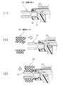
図2は、内側ボルト22と電流センサ40の取り付け方法を示す図である。まず(I)に示すように、IPM10の冷却水路構成部材14に設けられた螺子孔、つまりナット18が挿入された螺子孔に、内側ボルト22が挿入されて締め付けられる。
FIG. 2 is a diagram illustrating a method for attaching the
次に(II)に示すように、電流センサ40を矢印の方向に沿って移動させて、電流センサ40の貫通孔に内側ボルト22を挿入する。そして、電流センサ40の貫通孔に内側ボルト22を挿入した状態で、(III)に示すように、電流センサ40を矢印の方向に落とすことにより、電流センサ40の突起42と内側ボルト22の溝23が互いに嵌め合わされる(図1参照)。
Next, as shown in (II), the
さらに、図1に示すように、外側ボルトと内側ボルトの間にMGコネクタ30のバスバー32を挟んで、外側ボルトが内側ボルトに締め付けられる。
Further, as shown in FIG. 1, the outer bolt is fastened to the inner bolt by sandwiching the
次に、図1に示した各部分の形状について説明する。図3から図7には、図1に示した各部分の具体的な形状例が図示されている。 Next, the shape of each part shown in FIG. 1 will be described. 3 to 7 show specific shape examples of the respective parts shown in FIG.
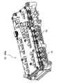
図3は、IPM(インテリジェントパワーモジュール)10を示す図である。図3には二重ボルトの内側ボルトが挿入される螺子孔側から見たIPM10の斜視図が示されている。図3において、IPM10には6個の螺子孔が設けられており、各螺子孔の開口部分までバスバー16が伸長されている。つまり、6個の螺子孔に対応した6個のバスバー16が設けられている。
FIG. 3 is a diagram showing an IPM (intelligent power module) 10. FIG. 3 is a perspective view of the
各バスバー16は、3相交流電力の各相に対応している。つまり、3つのバスバー16がU相、V相、W相の各々に対応している。図3に示すIPM10は、2つのモータジェネレータを制御する機能を備えており、UVW相に対応した3つのバスバー16を2組だけ備えている。なお、バスバー16を備えた各螺子孔に対して1本の内側ボルトが挿入される。
Each
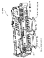
図4は、MGコネクタ30が取り付けられたIPM10を示す図である。つまり、図3に示すIPM10に、2つのMGコネクタ30a,30bを取り付けた状態の斜視図が、図4に示されている。IPM10が2つのモータジェネレータを制御する機能を備えているため、2つのモータジェネレータに対応した2つのMGコネクタ30a,30bが取り付けらている。なお、2つのMGコネクタ30a,30bとIPM10の間には電流センサ40が取り付けられている。
FIG. 4 is a diagram showing the
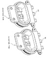
図5は、2つのMGコネクタ30a,30bを示す図である。MGコネクタ30aは、1つのモータジェネレータに対応しており、UVW相に対応した3つのバスバー32を備えている。そして、各バスバー32に設けられた孔を貫通するように1本の外側ボルトが挿入される。また、3つのバスバー32に対応した3つの接続端子34を備えている。なお、MGコネクタ30bもMGコネクタ30aと同じ構造である。
FIG. 5 shows two
図6は、電流センサ40を示す図であり、図6(A)は電流センサ40の斜視図であり図6(B)は電流センサ40の正面図である。電流センサ40には、6つの貫通孔41が設けられている。1つの貫通孔41がIPM10の1つの螺子孔(図3参照)に対応しており、1つの貫通孔41に1本の内側ボルトが挿入される。図6(B)には、貫通孔41内に設けられる突起42が図示されている。この突起42が内側ボルトに形成された溝に嵌め合わされる。なお、複数のピン44を介して、電流センサ40における電流の測定結果つまり二重ボルト内を流れる電流の測定結果を示す信号が、例えばIPM10などへ出力される。
FIG. 6 is a diagram illustrating the
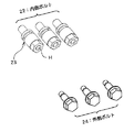
図7は、二重ボルトを構成する内側ボルト22と外側ボルト24を示す図である。図7には、3本の内側ボルト22と3本の外側ボルト24が図示されている。各内側ボルト22には溝23が設けられており、この溝23に、電流センサ40の突起42(図6参照)が嵌め合わされる。また、各内側ボルト22に設けられた螺子孔Hに、1本の外側ボルト24が挿入されて締め付けられる。
FIG. 7 is a view showing the
なお、内側ボルト22の軸の先端側には雄螺子が形成されており、内側ボルト22を回転させつつ、その軸の先端側をナット18(図1)に挿入することにより、内側ボルト22が締め付けられる。また、外側ボルト24の軸の先端側にも雄螺子が形成されており、内側ボルト22の螺子孔H内には雌螺子が形成されている。そして、外側ボルト24を回転させつつ、その軸の先端側を内側ボルト22の螺子孔Hに挿入することにより、外側ボルト24が締め付けられる。
A male screw is formed on the distal end side of the shaft of the
以上、本発明の好適な実施形態を説明したが、上述した実施形態は、あらゆる点で単なる例示にすぎず、本発明の範囲を限定するものではない。本発明は、その本質を逸脱しない範囲で各種の変形形態を包含する。例えば、本発明に係る電力変換装置は、燃料電池とバッテリを電力源とする燃料電池ハイブリッド自動車や、バッテリを電力源とする電気自動車等に搭載されてもよい。 As mentioned above, although preferred embodiment of this invention was described, embodiment mentioned above is only a mere illustration in all the points, and does not limit the scope of the present invention. The present invention includes various modifications without departing from the essence thereof. For example, the power converter according to the present invention may be mounted on a fuel cell hybrid vehicle using a fuel cell and a battery as a power source, an electric vehicle using a battery as a power source, and the like.
10 IPM、20 二重ボルト、22 内側ボルト、23 溝、24 外側ボルト、30 MGコネクタ、40 電流センサ 42 突起、100 PCU。
10 IPM, 20 double bolt, 22 inner bolt, 23 groove, 24 outer bolt, 30 MG connector, 40
Claims (3)
回転電機に電気的に接続されるコネクタと、
を有し、
前記コネクタは、内側ボルトと外側ボルトで構成された二重ボルトを用いて、前記電力変換モジュールに物理的に固定され且つ電気的に接続される、
ことを特徴とする電力変換装置。 A power conversion module that converts DC power and AC power to each other;
A connector electrically connected to the rotating electrical machine;
Have
The connector is physically fixed and electrically connected to the power conversion module using a double bolt composed of an inner bolt and an outer bolt.
The power converter characterized by the above-mentioned.
前記電力変換モジュールと前記コネクタの間に設けらる電流センサをさらに有し、
前記電流センサは、前記二重ボルトを貫通させる貫通孔を備え、
前記貫通孔内に設けられた突起と、前記貫通孔に挿入された二重ボルトの内側ボルトに形成された溝が、互いに嵌め合わされる、
ことを特徴とする電力変換装置。 The power conversion device according to claim 1,
A current sensor provided between the power conversion module and the connector;
The current sensor includes a through hole through which the double bolt penetrates,
The protrusion formed in the through hole and the groove formed in the inner bolt of the double bolt inserted into the through hole are fitted together.
The power converter characterized by the above-mentioned.
前記内側ボルトは、前記電力変換モジュールに設けられた螺子孔に挿入されて締め付けられ、これにより前記電力変換モジュールに前記内側ボルトが固定され、
前記外側ボルトは、前記内側ボルトに設けられた螺子孔に挿入されて締め付けられ、これにより前記内側ボルトと前記外側ボルトの間に前記コネクタが固定される、
ことを特徴とする電力変換装置。 In the power converter device according to claim 1 or 2,
The inner bolt is inserted and tightened into a screw hole provided in the power conversion module, whereby the inner bolt is fixed to the power conversion module,
The outer bolt is inserted into a screw hole provided in the inner bolt and tightened, whereby the connector is fixed between the inner bolt and the outer bolt.
The power converter characterized by the above-mentioned.
Priority Applications (1)
| Application Number | Priority Date | Filing Date | Title |
|---|---|---|---|
| JP2011017463A JP2012161122A (en) | 2011-01-31 | 2011-01-31 | Power conversion device |
Applications Claiming Priority (1)
| Application Number | Priority Date | Filing Date | Title |
|---|---|---|---|
| JP2011017463A JP2012161122A (en) | 2011-01-31 | 2011-01-31 | Power conversion device |
Publications (1)
| Publication Number | Publication Date |
|---|---|
| JP2012161122A true JP2012161122A (en) | 2012-08-23 |
Family
ID=46841227
Family Applications (1)
| Application Number | Title | Priority Date | Filing Date |
|---|---|---|---|
| JP2011017463A Withdrawn JP2012161122A (en) | 2011-01-31 | 2011-01-31 | Power conversion device |
Country Status (1)
| Country | Link |
|---|---|
| JP (1) | JP2012161122A (en) |
Cited By (3)
| Publication number | Priority date | Publication date | Assignee | Title |
|---|---|---|---|---|
| JP2018196213A (en) * | 2017-05-16 | 2018-12-06 | 株式会社デンソー | Power converter |
| US20190195916A1 (en) * | 2017-12-25 | 2019-06-27 | Toyota Jidosha Kabushiki Kaisha | Electrical device including sensor unit |
| EP4234297A1 (en) | 2022-02-25 | 2023-08-30 | Toyota Jidosha Kabushiki Kaisha | High-voltage cable connection structure |
-
2011
- 2011-01-31 JP JP2011017463A patent/JP2012161122A/en not_active Withdrawn
Cited By (8)
| Publication number | Priority date | Publication date | Assignee | Title |
|---|---|---|---|---|
| JP2018196213A (en) * | 2017-05-16 | 2018-12-06 | 株式会社デンソー | Power converter |
| US20190195916A1 (en) * | 2017-12-25 | 2019-06-27 | Toyota Jidosha Kabushiki Kaisha | Electrical device including sensor unit |
| CN109959803A (en) * | 2017-12-25 | 2019-07-02 | 丰田自动车株式会社 | Electrical equipment with sensor unit |
| JP2019114716A (en) * | 2017-12-25 | 2019-07-11 | トヨタ自動車株式会社 | Electrical apparatus equipped with sensor unit |
| US10877100B2 (en) | 2017-12-25 | 2020-12-29 | Toyota Jidosha Kabushiki Kaisha | Electrical device including sensor unit |
| CN109959803B (en) * | 2017-12-25 | 2021-06-18 | 丰田自动车株式会社 | Electrical equipment with sensor unit |
| EP4234297A1 (en) | 2022-02-25 | 2023-08-30 | Toyota Jidosha Kabushiki Kaisha | High-voltage cable connection structure |
| US12325367B2 (en) | 2022-02-25 | 2025-06-10 | Toyota Jidosha Kabushiki Kaisha | High-voltage cable connection structure |
Similar Documents
| Publication | Publication Date | Title |
|---|---|---|
| US8040088B2 (en) | Power inverter | |
| US8993890B2 (en) | Electric cable and electric connector | |
| US20160126802A1 (en) | Driving device and vehicle with the same | |
| EP2130735A3 (en) | Vehicle with electric hybrid powering of external loads and engine-off capability | |
| KR20170012779A (en) | External connecter of battery pack | |
| CN105827060A (en) | integrated electric drive system | |
| JP2014073811A (en) | Electric vehicle | |
| CN114342240A (en) | Conducting part for power conversion circuit | |
| JP2021076396A (en) | Sensor unit | |
| JP2015006116A (en) | Rotating electric machine for vehicles | |
| JP7056618B2 (en) | Mechanical and electrical integrated unit | |
| JP2013005550A (en) | Electric power conversion apparatus | |
| CN104540712A (en) | Fuse circuit body for vehicle | |
| JP6769406B2 (en) | Connecting member | |
| JP7294058B2 (en) | power converter | |
| US12614989B2 (en) | Power converter | |
| JP7571848B2 (en) | Power Conversion Unit | |
| JP7484601B2 (en) | Power Conversion Equipment | |
| JP2021001753A (en) | Sensor unit | |
| CN102638123A (en) | Rotating motor | |
| JP7263766B2 (en) | power converter | |
| JP2021197828A (en) | Power conversion device | |
| JP7120161B2 (en) | power converter | |
| KR20130015360A (en) | Inverter module | |
| JP4404791B2 (en) | Insulating member, power conversion device and vehicle |
Legal Events
| Date | Code | Title | Description |
|---|---|---|---|
| A300 | Withdrawal of application because of no request for examination |
Free format text: JAPANESE INTERMEDIATE CODE: A300 Effective date: 20140401 |