JP2012162999A - 内燃機関の吸気バルブ - Google Patents
内燃機関の吸気バルブ Download PDFInfo
- Publication number
- JP2012162999A JP2012162999A JP2011021919A JP2011021919A JP2012162999A JP 2012162999 A JP2012162999 A JP 2012162999A JP 2011021919 A JP2011021919 A JP 2011021919A JP 2011021919 A JP2011021919 A JP 2011021919A JP 2012162999 A JP2012162999 A JP 2012162999A
- Authority
- JP
- Japan
- Prior art keywords
- valve
- valve body
- intake
- internal combustion
- combustion engine
- Prior art date
- Legal status (The legal status is an assumption and is not a legal conclusion. Google has not performed a legal analysis and makes no representation as to the accuracy of the status listed.)
- Granted
Links
Images


Classifications
-
- F—MECHANICAL ENGINEERING; LIGHTING; HEATING; WEAPONS; BLASTING
- F01—MACHINES OR ENGINES IN GENERAL; ENGINE PLANTS IN GENERAL; STEAM ENGINES
- F01L—CYCLICALLY OPERATING VALVES FOR MACHINES OR ENGINES
- F01L3/00—Lift-valve, i.e. cut-off apparatus with closure members having at least a component of their opening and closing motion perpendicular to the closing faces; Parts or accessories thereof
- F01L3/02—Selecting particular materials for valve-members or valve-seats; Valve-members or valve-seats composed of two or more materials
-
- B—PERFORMING OPERATIONS; TRANSPORTING
- B23—MACHINE TOOLS; METAL-WORKING NOT OTHERWISE PROVIDED FOR
- B23P—METAL-WORKING NOT OTHERWISE PROVIDED FOR; COMBINED OPERATIONS; UNIVERSAL MACHINE TOOLS
- B23P15/00—Making specific metal objects by operations not covered by a single other subclass or a group in this subclass
- B23P15/001—Making specific metal objects by operations not covered by a single other subclass or a group in this subclass valves or valve housings
- B23P15/002—Making specific metal objects by operations not covered by a single other subclass or a group in this subclass valves or valve housings poppet valves
-
- F—MECHANICAL ENGINEERING; LIGHTING; HEATING; WEAPONS; BLASTING
- F01—MACHINES OR ENGINES IN GENERAL; ENGINE PLANTS IN GENERAL; STEAM ENGINES
- F01L—CYCLICALLY OPERATING VALVES FOR MACHINES OR ENGINES
- F01L3/00—Lift-valve, i.e. cut-off apparatus with closure members having at least a component of their opening and closing motion perpendicular to the closing faces; Parts or accessories thereof
- F01L3/12—Cooling of valves
- F01L3/14—Cooling of valves by means of a liquid or solid coolant, e.g. sodium, in a closed chamber in a valve
-
- Y—GENERAL TAGGING OF NEW TECHNOLOGICAL DEVELOPMENTS; GENERAL TAGGING OF CROSS-SECTIONAL TECHNOLOGIES SPANNING OVER SEVERAL SECTIONS OF THE IPC; TECHNICAL SUBJECTS COVERED BY FORMER USPC CROSS-REFERENCE ART COLLECTIONS [XRACs] AND DIGESTS
- Y10—TECHNICAL SUBJECTS COVERED BY FORMER USPC
- Y10T—TECHNICAL SUBJECTS COVERED BY FORMER US CLASSIFICATION
- Y10T29/00—Metal working
- Y10T29/49—Method of mechanical manufacture
- Y10T29/49229—Prime mover or fluid pump making
- Y10T29/49298—Poppet or I.C. engine valve or valve seat making
- Y10T29/49307—Composite or hollow valve stem or head making
- Y10T29/49313—Composite or hollow valve stem or head making including casting
Landscapes
- Engineering & Computer Science (AREA)
- Mechanical Engineering (AREA)
- General Engineering & Computer Science (AREA)
- Valve-Gear Or Valve Arrangements (AREA)
- Lift Valve (AREA)
Abstract
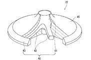
【解決手段】弁体22の中心からバルブステム23が延設されて構成された内燃機関(エンジン)の吸気バルブ20において、前記弁体22は、弁体骨格部40の外側に弁体肉部45が設けられてなり、前記弁体骨格部40及び前記バルブステム23が鉄系材料にて構成されると共に、前記弁体肉部45がアルミニウム合金材料にて構成されたものである。
【選択図】 図2
Description
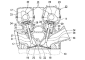
図1は、本発明に係る内燃機関の吸気バルブにおける第1実施形態が適用されたエンジンの動弁装置を示す断面図である。この図1に示すエンジン10は、例えば自動二輪車に搭載されたエンジンであり、そのシリンダヘッド11及びヘッドカバー12内に動弁装置、本実施形態ではDOHC式の動弁装置14を備える。
図7は、本発明に係る内燃機関の吸気バルブにおける第2実施形態を示す分解斜視図である。この第2実施形態において、前記第1実施形態と同様な部分については、同一の符号を付すことにより説明を簡略化し、または省略する。
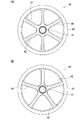
図8は、本発明に係る内燃機関の吸気バルブにおける第3実施形態を示し、弁体における弁体骨格部の正面図である。この第3実施形態において、前記第1実施形態と同様な部分については、同一の符号を付すことにより説明を簡略化し、または省略する。
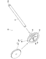
図9は、本発明に係る内燃機関の吸気バルブにおける第4実施形態を示す弁体における弁体骨格部とバルブステムの斜視図である。この第4実施形態において、前記第1実施形態と同様な部分については、同一の符号を付すことにより説明を簡略化し、または省略する。
18 バルブシート
20 吸気バルブ
22 弁体
23 バルブステム
23A ステム端部
29 吸気側カム
31 吸気側バルブスプリング
40 弁体骨格部
41 中心部位
42 スポーク部位
43 リング部位(バルブシート接触部)
45 弁体肉部
50 弁体
55 弁体骨格部
56 プレート部位
57 穴
R1、R2 曲率半径
Claims (8)
- 弁体の中心からバルブステムが延設されて構成された内燃機関の吸気バルブにおいて、
前記弁体は、弁体骨格部の外側に弁体肉部が設けられてなり、
前記弁体骨格部及び前記バルブステムが鉄系材料にて構成されると共に、前記弁体肉部がアルミニウム合金材料にて構成されたことを特徴とする内燃機関の吸気バルブ。 - 前記弁体は、弁体骨格部の表面側及び裏面側に弁体肉部が設けられたことを特徴とする請求項1に記載の内燃機関の吸気バルブ。
- 前記弁体は、弁体肉部が弁体骨格部を包み込むように鋳込み成形されて構成されたことを特徴とする請求項2に記載の内燃機関の吸気バルブ。
- 前記弁体の弁体骨格部には、表面側と裏面側とを貫通する穴が複数形成されたことを特徴とする請求項2に記載の内燃機関の吸気バルブ。
- 前記弁体の弁体骨格部は、中心部位から放射状に延びる複数本のスポーク部位と、このスポーク部位の外側端に結合される円環状のリング部位と、を有して構成されたことを特徴とする請求項2に記載の内燃機関の吸気バルブ。
- 前記弁体の弁体骨格部は、バルブステムと一体または別体に構成されたことを特徴とする請求項1に記載の内燃機関の吸気バルブ。
- 前記弁体では、弁体骨格部における裏面側の曲率半径が、弁体肉部における裏面側の曲率半径よりも大きく形成されたことを特徴とする請求項1に記載の内燃機関の吸気バルブ。
- 前記弁体の弁体骨格部における外周部は弁体肉部から露出し、バルブシートに接触可能なバルブシート接触部として構成されたことを特徴とする請求項1に記載の内燃機関の吸気バルブ。
Priority Applications (4)
| Application Number | Priority Date | Filing Date | Title |
|---|---|---|---|
| JP2011021919A JP5625967B2 (ja) | 2011-02-03 | 2011-02-03 | 内燃機関の吸気バルブ |
| US13/358,048 US8893680B2 (en) | 2011-02-03 | 2012-01-25 | Intake valve of internal combustion engine |
| EP12152362.5A EP2484482B1 (en) | 2011-02-03 | 2012-01-25 | Intake valve of internal combustion engine |
| ES12152362.5T ES2543639T3 (es) | 2011-02-03 | 2012-01-25 | Válvula de admisión de motor de combustión interna |
Applications Claiming Priority (1)
| Application Number | Priority Date | Filing Date | Title |
|---|---|---|---|
| JP2011021919A JP5625967B2 (ja) | 2011-02-03 | 2011-02-03 | 内燃機関の吸気バルブ |
Publications (2)
| Publication Number | Publication Date |
|---|---|
| JP2012162999A true JP2012162999A (ja) | 2012-08-30 |
| JP5625967B2 JP5625967B2 (ja) | 2014-11-19 |
Family
ID=45524389
Family Applications (1)
| Application Number | Title | Priority Date | Filing Date |
|---|---|---|---|
| JP2011021919A Active JP5625967B2 (ja) | 2011-02-03 | 2011-02-03 | 内燃機関の吸気バルブ |
Country Status (4)
| Country | Link |
|---|---|
| US (1) | US8893680B2 (ja) |
| EP (1) | EP2484482B1 (ja) |
| JP (1) | JP5625967B2 (ja) |
| ES (1) | ES2543639T3 (ja) |
Cited By (1)
| Publication number | Priority date | Publication date | Assignee | Title |
|---|---|---|---|---|
| DE102018102574A1 (de) | 2017-02-08 | 2018-08-09 | Toyota Jidosha Kabushiki Kaisha | Motorventil |
Families Citing this family (4)
| Publication number | Priority date | Publication date | Assignee | Title |
|---|---|---|---|---|
| JP5964134B2 (ja) * | 2012-05-23 | 2016-08-03 | 愛三工業株式会社 | 吸気用エンジンバルブ |
| US9995187B2 (en) | 2016-01-26 | 2018-06-12 | Honda Motor Co., Ltd. | Intake valve apparatus for use with a combustion engine and methods of use and manufacture thereof |
| US10760455B2 (en) * | 2016-12-20 | 2020-09-01 | Caterpillar Inc. | Poppet valve for an internal combustion engine |
| DE102023200287A1 (de) * | 2023-01-16 | 2024-08-01 | Mahle International Gmbh | Ventil für eine Brennkraftmaschine und Herstellungsverfahren |
Citations (3)
| Publication number | Priority date | Publication date | Assignee | Title |
|---|---|---|---|---|
| GB123416A (en) * | 1918-02-28 | 1919-02-27 | John Buchanan | Composite Valve for all Classes of Internal Combustion Engines. |
| JP2003343219A (ja) * | 2002-05-27 | 2003-12-03 | Isao Shirayanagi | エンジンの吸排気弁 |
| JP2004150349A (ja) * | 2002-10-30 | 2004-05-27 | Isao Shirayanagi | エンジン弁の冷却構造 |
Family Cites Families (11)
| Publication number | Priority date | Publication date | Assignee | Title |
|---|---|---|---|---|
| US1557022A (en) | 1922-11-03 | 1925-10-13 | Aeromarine Plane & Motor Compa | Valve and method of making same |
| US2162063A (en) | 1936-02-29 | 1939-06-13 | Thompson Prod Inc | Valve and a method of making the same |
| JPS5726216A (en) | 1980-07-24 | 1982-02-12 | Kobe Steel Ltd | Production of exhaust valve for internal combustion engine |
| JPS61202606A (ja) | 1985-03-04 | 1986-09-08 | 株式会社クボタ | 農用トラクタ |
| JPS61202606U (ja) | 1985-06-10 | 1986-12-19 | ||
| JP2002089213A (ja) | 2000-09-19 | 2002-03-27 | Fuji Oozx Inc | エンジンバルブ及びその製造方法 |
| DE10160942A1 (de) | 2001-12-12 | 2003-06-18 | Daimler Chrysler Ag | Gebautes Ventil für Hubkolbenmaschinen |
| DE10204122C1 (de) | 2002-02-01 | 2003-05-08 | Daimler Chrysler Ag | Gebautes Ventil für Hubkolbenmaschinen und Verfahren zu dessen Herstellung |
| WO2003100223A1 (de) | 2002-05-28 | 2003-12-04 | Daimlerchrysler Ag | Verfahren zur herstellung eines gebauten ventils mit hohlschaft für hubkolbenmaschinen |
| JP2004308607A (ja) | 2003-04-09 | 2004-11-04 | Isao Shirayanagi | エンジン弁とその製造方法 |
| DE10354077B4 (de) | 2003-11-19 | 2005-10-20 | Daimler Chrysler Ag | Leichtbauventil |
-
2011
- 2011-02-03 JP JP2011021919A patent/JP5625967B2/ja active Active
-
2012
- 2012-01-25 ES ES12152362.5T patent/ES2543639T3/es active Active
- 2012-01-25 EP EP12152362.5A patent/EP2484482B1/en active Active
- 2012-01-25 US US13/358,048 patent/US8893680B2/en active Active
Patent Citations (3)
| Publication number | Priority date | Publication date | Assignee | Title |
|---|---|---|---|---|
| GB123416A (en) * | 1918-02-28 | 1919-02-27 | John Buchanan | Composite Valve for all Classes of Internal Combustion Engines. |
| JP2003343219A (ja) * | 2002-05-27 | 2003-12-03 | Isao Shirayanagi | エンジンの吸排気弁 |
| JP2004150349A (ja) * | 2002-10-30 | 2004-05-27 | Isao Shirayanagi | エンジン弁の冷却構造 |
Cited By (1)
| Publication number | Priority date | Publication date | Assignee | Title |
|---|---|---|---|---|
| DE102018102574A1 (de) | 2017-02-08 | 2018-08-09 | Toyota Jidosha Kabushiki Kaisha | Motorventil |
Also Published As
| Publication number | Publication date |
|---|---|
| EP2484482A1 (en) | 2012-08-08 |
| EP2484482B1 (en) | 2015-06-03 |
| US8893680B2 (en) | 2014-11-25 |
| US20120199092A1 (en) | 2012-08-09 |
| JP5625967B2 (ja) | 2014-11-19 |
| ES2543639T3 (es) | 2015-08-20 |
Similar Documents
| Publication | Publication Date | Title |
|---|---|---|
| JP5625967B2 (ja) | 内燃機関の吸気バルブ | |
| CN101371010B (zh) | 内燃发动机的凸轮轴支撑结构及其装配方法 | |
| US9593642B2 (en) | Composite cam carrier | |
| US8567362B2 (en) | Vehicle engine | |
| JP6147699B2 (ja) | 吸気バルブ及びこれを備えた吸排気装置 | |
| US8413626B2 (en) | Lash adjuster | |
| US8522738B2 (en) | Vehicle engine | |
| TWI652403B (zh) | 引擎 | |
| JP2010048206A (ja) | エンジンの動弁装置 | |
| JP5742956B2 (ja) | カムシャフト支持構造 | |
| JP4715762B2 (ja) | エンジンの可変動弁装置 | |
| JP6327018B2 (ja) | エンジンの動弁構造 | |
| JP2007077962A (ja) | 可変動弁機構の組み付け方法 | |
| JP4715763B2 (ja) | エンジンの可変動弁装置 | |
| JP4190210B2 (ja) | エンジンの吸排気弁 | |
| JP2003328711A (ja) | エンジンの動弁装置 | |
| JP5240018B2 (ja) | 内燃機関のラッシュアジャスタ支持構造 | |
| JP5712025B2 (ja) | エンジン用動弁機構におけるロッカアーム支持構造 | |
| JP2008240671A (ja) | 組立式エンジン弁 | |
| JP2012162998A (ja) | 内燃機関のバルブスプリングシート | |
| JP2008190449A (ja) | エンジンの可変動弁装置 | |
| JP2007056800A (ja) | 内燃機関の動弁機構 | |
| JP2005083256A (ja) | スプリングリテーナ並びに該スプリングリテーナを具備するエンジン及び自動二輪車 | |
| JP2007332888A (ja) | 可変動弁機構 |
Legal Events
| Date | Code | Title | Description |
|---|---|---|---|
| A621 | Written request for application examination |
Free format text: JAPANESE INTERMEDIATE CODE: A621 Effective date: 20131010 |
|
| RD02 | Notification of acceptance of power of attorney |
Free format text: JAPANESE INTERMEDIATE CODE: A7422 Effective date: 20131010 |
|
| A977 | Report on retrieval |
Free format text: JAPANESE INTERMEDIATE CODE: A971007 Effective date: 20140520 |
|
| A131 | Notification of reasons for refusal |
Free format text: JAPANESE INTERMEDIATE CODE: A131 Effective date: 20140527 |
|
| A521 | Written amendment |
Free format text: JAPANESE INTERMEDIATE CODE: A523 Effective date: 20140717 |
|
| TRDD | Decision of grant or rejection written | ||
| A01 | Written decision to grant a patent or to grant a registration (utility model) |
Free format text: JAPANESE INTERMEDIATE CODE: A01 Effective date: 20140902 |
|
| A61 | First payment of annual fees (during grant procedure) |
Free format text: JAPANESE INTERMEDIATE CODE: A61 Effective date: 20140915 |
|
| R151 | Written notification of patent or utility model registration |
Ref document number: 5625967 Country of ref document: JP Free format text: JAPANESE INTERMEDIATE CODE: R151 |