JP2012170969A - 穴抜き加工装置 - Google Patents
穴抜き加工装置 Download PDFInfo
- Publication number
- JP2012170969A JP2012170969A JP2011033829A JP2011033829A JP2012170969A JP 2012170969 A JP2012170969 A JP 2012170969A JP 2011033829 A JP2011033829 A JP 2011033829A JP 2011033829 A JP2011033829 A JP 2011033829A JP 2012170969 A JP2012170969 A JP 2012170969A
- Authority
- JP
- Japan
- Prior art keywords
- blade portion
- punch
- metal plate
- hole
- die
- Prior art date
- Legal status (The legal status is an assumption and is not a legal conclusion. Google has not performed a legal analysis and makes no representation as to the accuracy of the status listed.)
- Granted
Links
Images


Landscapes
- Punching Or Piercing (AREA)
Abstract
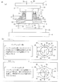
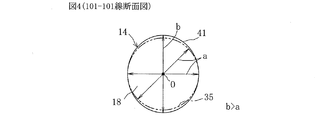
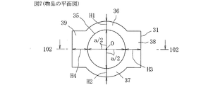
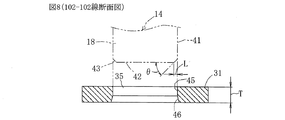
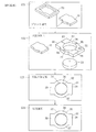
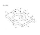
【解決手段】プレス機械1に用いられるパンチ14の刃部18は水平方向の横断面形状が楕円形で上下方向に直線的に延びる棒状になっている。そして、刃部18が金属板31に穴抜き加工を行った後、刃部18が金属板31に形成された楕円形の穴32から抜き取られることにより、楕円形の長辺の側における幅の狭い周囲部分36;37が穴の中心の方向に収縮し、楕円形の穴32が真円形の穴35に変化するようになっている。刃部18に面取り部43が形成されたことで、刃部18の外周面41が真円形の穴35の内周面を擦り金属板31の上面から板厚の1/2乃至2/3程度の範囲が剪断面45となり、真円形の穴35を軸受孔として使用可能になる。
【選択図】図1
Description
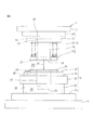
本明細書における「前」、「後」、「左」、「右」、「上」、「下」の方向は、図1のa図の状態又は図2の状態にプレス機械1を置いて図1のa図又は図2の紙面の前側から見た場合に特定される方向である。
Claims (2)
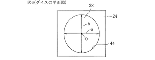
- 金属板に真円形の穴を幅の狭い周囲部分と幅の広い周囲部分とで囲まれるようにプレス機械による穴抜き加工で形成する穴抜き加工装置であって、パンチの刃部は横断面形状が楕円形で上下方向に直線的に延びる棒状になっており、このパンチの刃部の楕円形の長辺が上記幅の狭い周囲部分の方向に配置されるようにパンチがプレス機械のスライドに取り付けられた一方、ダイスの刃部は横断面形状が楕円形で上下方向に貫通する貫通孔になっており、スライドの下降運動でポンチの刃部がダイスの刃部に挿入された場合にパンチの刃部の外周面とダイスの刃部の内周面との間に隙間を生じない程度にパンチの刃部とダイスの刃部とが互いに嵌め合わされるようにダイスの刃部の楕円形の長辺が上記幅の狭い周囲部分の方向に配置されるようにダイスがプレス機械のボルスターに取り付けられたことを特徴とする穴抜き加工装置。
- パンチの刃部の外周面と下面とが交わる縁部に面取り部を上記刃部の円周方向の全体にわたり連続した態様に形成したことを特徴とする請求項1記載の穴抜き加工装置。
Priority Applications (1)
| Application Number | Priority Date | Filing Date | Title |
|---|---|---|---|
| JP2011033829A JP5731226B2 (ja) | 2011-02-18 | 2011-02-18 | 穴抜き加工装置 |
Applications Claiming Priority (1)
| Application Number | Priority Date | Filing Date | Title |
|---|---|---|---|
| JP2011033829A JP5731226B2 (ja) | 2011-02-18 | 2011-02-18 | 穴抜き加工装置 |
Publications (2)
| Publication Number | Publication Date |
|---|---|
| JP2012170969A true JP2012170969A (ja) | 2012-09-10 |
| JP5731226B2 JP5731226B2 (ja) | 2015-06-10 |
Family
ID=46974369
Family Applications (1)
| Application Number | Title | Priority Date | Filing Date |
|---|---|---|---|
| JP2011033829A Active JP5731226B2 (ja) | 2011-02-18 | 2011-02-18 | 穴抜き加工装置 |
Country Status (1)
| Country | Link |
|---|---|
| JP (1) | JP5731226B2 (ja) |
Cited By (2)
| Publication number | Priority date | Publication date | Assignee | Title |
|---|---|---|---|---|
| CN112222261A (zh) * | 2020-09-25 | 2021-01-15 | 中国航发哈尔滨轴承有限公司 | 关节轴承缺口加工方法 |
| CN119500875A (zh) * | 2025-01-15 | 2025-02-25 | 成都工业职业技术学院 | 一种智能化切边冲孔装置的控制方法 |
Families Citing this family (1)
| Publication number | Priority date | Publication date | Assignee | Title |
|---|---|---|---|---|
| WO2024154727A1 (ja) * | 2023-01-20 | 2024-07-25 | 三菱電機株式会社 | プレス装置、鉄心の製造方法、回転電機の製造方法、および、回転電機 |
Citations (6)
| Publication number | Priority date | Publication date | Assignee | Title |
|---|---|---|---|---|
| JPS61289922A (ja) * | 1985-06-17 | 1986-12-19 | Yoneda Seisakusho:Kk | 円板状小物部品の軸孔打抜き方法 |
| JPH04108921U (ja) * | 1991-02-27 | 1992-09-21 | 大和工業株式会社 | 穴あけポンチ |
| JPH06133497A (ja) * | 1992-10-13 | 1994-05-13 | Mitsubishi Electric Corp | 遊星歯車式減速スタータの出力回転軸の製造方法 |
| JPH07214193A (ja) * | 1994-02-02 | 1995-08-15 | Iijima Seimitsu Kogyo Kk | プレス機械の精密せん断金型 |
| JP2002083558A (ja) * | 2000-06-22 | 2002-03-22 | Hitachi Ltd | ブラウン管および電子銃用電極板およびその製造方法 |
| JP2008280963A (ja) * | 2007-05-14 | 2008-11-20 | Nakanishi Metal Works Co Ltd | ロッカーアームの製造方法 |
-
2011
- 2011-02-18 JP JP2011033829A patent/JP5731226B2/ja active Active
Patent Citations (6)
| Publication number | Priority date | Publication date | Assignee | Title |
|---|---|---|---|---|
| JPS61289922A (ja) * | 1985-06-17 | 1986-12-19 | Yoneda Seisakusho:Kk | 円板状小物部品の軸孔打抜き方法 |
| JPH04108921U (ja) * | 1991-02-27 | 1992-09-21 | 大和工業株式会社 | 穴あけポンチ |
| JPH06133497A (ja) * | 1992-10-13 | 1994-05-13 | Mitsubishi Electric Corp | 遊星歯車式減速スタータの出力回転軸の製造方法 |
| JPH07214193A (ja) * | 1994-02-02 | 1995-08-15 | Iijima Seimitsu Kogyo Kk | プレス機械の精密せん断金型 |
| JP2002083558A (ja) * | 2000-06-22 | 2002-03-22 | Hitachi Ltd | ブラウン管および電子銃用電極板およびその製造方法 |
| JP2008280963A (ja) * | 2007-05-14 | 2008-11-20 | Nakanishi Metal Works Co Ltd | ロッカーアームの製造方法 |
Cited By (2)
| Publication number | Priority date | Publication date | Assignee | Title |
|---|---|---|---|---|
| CN112222261A (zh) * | 2020-09-25 | 2021-01-15 | 中国航发哈尔滨轴承有限公司 | 关节轴承缺口加工方法 |
| CN119500875A (zh) * | 2025-01-15 | 2025-02-25 | 成都工业职业技术学院 | 一种智能化切边冲孔装置的控制方法 |
Also Published As
| Publication number | Publication date |
|---|---|
| JP5731226B2 (ja) | 2015-06-10 |
Similar Documents
| Publication | Publication Date | Title |
|---|---|---|
| JP6538419B2 (ja) | 金型装置及び薄板材の打抜き方法 | |
| US11224909B2 (en) | Protrusion molding device, protrusion molding method, and molded article | |
| CN101176895A (zh) | 冲压加工装置及其方法 | |
| KR101454793B1 (ko) | 핫스탬핑된 초고강도 소재의 프레스 절단금형 손상 방지용 2단계 전단가공방법 | |
| JP2008119704A (ja) | プレス加工装置 | |
| JP5494449B2 (ja) | 金属板打ち抜き加工方法及び装置と回転電機鉄心の製造方法 | |
| JP5731226B2 (ja) | 穴抜き加工装置 | |
| AU2016291507A1 (en) | Protrusion molding device, protrusion molding method, and molded article | |
| EP1949985A1 (en) | Method for manufacturing ring-shaped member | |
| JP3167681U (ja) | プレス型 | |
| JP2012115893A (ja) | 金属板の打ち抜き加工方法及び装置と回転電機鉄心の製造方法 | |
| CA2573116C (en) | Method and arrangement for production of stampings | |
| JP2013202668A (ja) | 打ち抜き加工装置および打ち抜き加工方法 | |
| CN208800637U (zh) | 一种质量环近距离冲孔模具 | |
| JP2007190570A (ja) | プレス送り込み方法及びその設備 | |
| JP2016203200A (ja) | 下金型 | |
| JP2020037127A (ja) | 金型、パンチ、ダイ、および加工方法 | |
| JP2016124020A (ja) | 無段変速機用ベルトのエレメント形成方法及び装置 | |
| KR20150096980A (ko) | 무른 금속 플레이트의 펀칭 방법 | |
| JP2006346703A (ja) | プレス加工方法 | |
| CN111936247B (zh) | 废料部的废料上升防止方法 | |
| AU2022377026A1 (en) | Method and apparatus for producing a calibrated stamped part | |
| JP2007105791A (ja) | 抜き型 | |
| JP2009172612A (ja) | プレス加工金型、及び加工板材の製造方法 | |
| JP2007135314A (ja) | 回転子積層鉄心の製造方法 |
Legal Events
| Date | Code | Title | Description |
|---|---|---|---|
| A621 | Written request for application examination |
Free format text: JAPANESE INTERMEDIATE CODE: A621 Effective date: 20140110 |
|
| A131 | Notification of reasons for refusal |
Free format text: JAPANESE INTERMEDIATE CODE: A131 Effective date: 20141015 |
|
| A977 | Report on retrieval |
Free format text: JAPANESE INTERMEDIATE CODE: A971007 Effective date: 20141016 |
|
| A521 | Request for written amendment filed |
Free format text: JAPANESE INTERMEDIATE CODE: A523 Effective date: 20141215 |
|
| TRDD | Decision of grant or rejection written | ||
| A01 | Written decision to grant a patent or to grant a registration (utility model) |
Free format text: JAPANESE INTERMEDIATE CODE: A01 Effective date: 20150331 |
|
| A61 | First payment of annual fees (during grant procedure) |
Free format text: JAPANESE INTERMEDIATE CODE: A61 Effective date: 20150409 |
|
| R150 | Certificate of patent or registration of utility model |
Ref document number: 5731226 Country of ref document: JP Free format text: JAPANESE INTERMEDIATE CODE: R150 |
|
| R250 | Receipt of annual fees |
Free format text: JAPANESE INTERMEDIATE CODE: R250 |
|
| R250 | Receipt of annual fees |
Free format text: JAPANESE INTERMEDIATE CODE: R250 |
|
| R250 | Receipt of annual fees |
Free format text: JAPANESE INTERMEDIATE CODE: R250 |
|
| R250 | Receipt of annual fees |
Free format text: JAPANESE INTERMEDIATE CODE: R250 |
|
| R250 | Receipt of annual fees |
Free format text: JAPANESE INTERMEDIATE CODE: R250 |
|
| R250 | Receipt of annual fees |
Free format text: JAPANESE INTERMEDIATE CODE: R250 |
|
| R250 | Receipt of annual fees |
Free format text: JAPANESE INTERMEDIATE CODE: R250 |
|
| R250 | Receipt of annual fees |
Free format text: JAPANESE INTERMEDIATE CODE: R250 |
|
| R250 | Receipt of annual fees |
Free format text: JAPANESE INTERMEDIATE CODE: R250 |