JP2012177806A - 紫外レーザ装置 - Google Patents
紫外レーザ装置 Download PDFInfo
- Publication number
- JP2012177806A JP2012177806A JP2011040876A JP2011040876A JP2012177806A JP 2012177806 A JP2012177806 A JP 2012177806A JP 2011040876 A JP2011040876 A JP 2011040876A JP 2011040876 A JP2011040876 A JP 2011040876A JP 2012177806 A JP2012177806 A JP 2012177806A
- Authority
- JP
- Japan
- Prior art keywords
- light
- crystal
- ultraviolet laser
- lbo
- wavelength conversion
- Prior art date
- Legal status (The legal status is an assumption and is not a legal conclusion. Google has not performed a legal analysis and makes no representation as to the accuracy of the status listed.)
- Granted
Links
Images





Classifications
-
- H—ELECTRICITY
- H01—ELECTRIC ELEMENTS
- H01S—DEVICES USING THE PROCESS OF LIGHT AMPLIFICATION BY STIMULATED EMISSION OF RADIATION [LASER] TO AMPLIFY OR GENERATE LIGHT; DEVICES USING STIMULATED EMISSION OF ELECTROMAGNETIC RADIATION IN WAVE RANGES OTHER THAN OPTICAL
- H01S3/00—Lasers, i.e. devices using stimulated emission of electromagnetic radiation in the infrared, visible or ultraviolet wave range
- H01S3/02—Constructional details
- H01S3/025—Constructional details of solid state lasers, e.g. housings or mountings
-
- H—ELECTRICITY
- H01—ELECTRIC ELEMENTS
- H01S—DEVICES USING THE PROCESS OF LIGHT AMPLIFICATION BY STIMULATED EMISSION OF RADIATION [LASER] TO AMPLIFY OR GENERATE LIGHT; DEVICES USING STIMULATED EMISSION OF ELECTROMAGNETIC RADIATION IN WAVE RANGES OTHER THAN OPTICAL
- H01S3/00—Lasers, i.e. devices using stimulated emission of electromagnetic radiation in the infrared, visible or ultraviolet wave range
- H01S3/10—Controlling the intensity, frequency, phase, polarisation or direction of the emitted radiation, e.g. switching, gating, modulating or demodulating
- H01S3/106—Controlling the intensity, frequency, phase, polarisation or direction of the emitted radiation, e.g. switching, gating, modulating or demodulating by controlling devices placed within the cavity
- H01S3/108—Controlling the intensity, frequency, phase, polarisation or direction of the emitted radiation, e.g. switching, gating, modulating or demodulating by controlling devices placed within the cavity using non-linear optical devices, e.g. exhibiting Brillouin or Raman scattering
- H01S3/109—Frequency multiplication, e.g. harmonic generation
-
- H—ELECTRICITY
- H01—ELECTRIC ELEMENTS
- H01S—DEVICES USING THE PROCESS OF LIGHT AMPLIFICATION BY STIMULATED EMISSION OF RADIATION [LASER] TO AMPLIFY OR GENERATE LIGHT; DEVICES USING STIMULATED EMISSION OF ELECTROMAGNETIC RADIATION IN WAVE RANGES OTHER THAN OPTICAL
- H01S3/00—Lasers, i.e. devices using stimulated emission of electromagnetic radiation in the infrared, visible or ultraviolet wave range
- H01S3/05—Construction or shape of optical resonators; Accommodation of active medium therein; Shape of active medium
- H01S3/08—Construction or shape of optical resonators or components thereof
- H01S3/081—Construction or shape of optical resonators or components thereof comprising three or more reflectors
- H01S3/0813—Configuration of resonator
- H01S3/0815—Configuration of resonator having 3 reflectors, e.g. V-shaped resonators
Landscapes
- Physics & Mathematics (AREA)
- Electromagnetism (AREA)
- Engineering & Computer Science (AREA)
- Plasma & Fusion (AREA)
- Optics & Photonics (AREA)
- Nonlinear Science (AREA)
- Optical Modulation, Optical Deflection, Nonlinear Optics, Optical Demodulation, Optical Logic Elements (AREA)
- Lasers (AREA)
Abstract
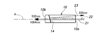
【解決手段】基本波光21を発生する固体レーザ発振媒体8と、基本波光21およびその第二次高調波光22を入射光として紫外レーザである第三次高調波光23に波長変換するLBO波長変換結晶10とを有する紫外レーザ装置1において、基本波光21および第二次高調波光22を透過させ且つ第三次高調波光23を反射させる反射面14を、LBO波長変換結晶10の内部に基本波光21および第二次高調波光22の光軸Aに対して傾斜する向きに形成する。
【選択図】図1
Description
次に、図4を参照して第1変形例に係る紫外レーザ装置1について説明する。なお、上記実施形態と同様の部材や部位については同一の符号を付し、重複する説明は省略する。以下の変形例においても同様とする。
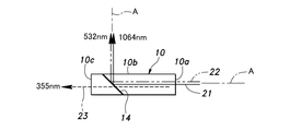
また、図5に示すように、反射面14が基本波光21および第二次高調波光22の光軸Aに対して45度よりも大きな角度をもって傾斜するように形成し、さらに、紫外レーザがLBO波長変換結晶10の第1の面10aから出射するような形態とすることもできる。このように構成しても、紫外レーザが第1の面10aにおける基本波光21および第二次高調波光22の経路と異なる部位を通ってLBO波長変換結晶10から出射するため、第1変形例と同様に上記実施形態と同様の効果を得ることができる。
次に、図6および図7を参照して第3変形例について説明する。本変形例の紫外レーザ装置1においても、LBO波長変換結晶10の反射面14を介して対峙するように配置された一対の共振器ミラー5,6により共振器7が構成されている。共振器ミラー5と共振器ミラー6との間の屈曲する基本波光21の光路上には、共振器ミラー5側から順に固体レーザ発振媒体8、KTP波長変換結晶9およびLBO波長変換結晶10が配置されている。共振器ミラー5は、光励起用の波長のレーザ光を透過させ、固体レーザ発振媒体8から出力される波長1064nmの基本波光21を反射する特性とされ、共振器ミラー6は、波長1064nmの基本波光21を反射し且つ波長532nmの第二次高調波光22を透過させる特性とされている。
また、図8に示すように、第3変形例の共振器7に対し、第2変形例(図5)で示したような反射面14の傾斜角度を適用し、波長1064nmの基本波光21および波長532nmの第二次高調波光22がLBO波長変換結晶10の第1の面10aから出射し、第三次高調波光23が第1の面10aに対峙する位置に配置された第3の面10cから出射するような形態とすることも可能である。このように構成しても、上記実施形態と同様の効果を得ることができる。
8 固体レーザ発振媒体(レーザ光源)
10 LBO波長変換結晶
11 第1LBO結晶
12 第2LBO結晶
13 誘電体多層膜(コート)
14 反射面
21 基本波光
22 第二次高調波光
23 第三次高調波光(レーザ光)
A 光軸
Claims (5)
- 基本波光を発生するレーザ光源と、当該基本波光およびその高調波光のうち少なくとも一方を入射光として紫外レーザに波長変換する波長変換結晶とを有する紫外レーザ装置であって、
前記基本波光およびその高調波光のうち少なくとも一方と前記紫外レーザとのどちらか一方を透過させ且つどちから他方を反射させる反射面を、前記波長変換結晶の内部に前記基本波光およびその高調波光のうち少なくとも一方の光軸に対して傾斜する向きに形成したことを特徴とする紫外レーザ装置。 - 前記波長変換結晶は、前記反射面に対して一方に配置された第1結晶と、前記反射面に対して他方に配置された第2結晶とを含み、
前記反射面は、前記第1結晶に設けられたコートにより形成されることを特徴とする、請求項1に記載の紫外レーザ装置。 - 前記第2結晶は、前記第1結晶に設けられた前記コートの表面にオプチカルコンタクトで一体接合されたことを特徴とする、請求項2に記載の紫外レーザ装置。
- 前記第1結晶は位相整合条件を満たす結晶切り出し角度を有し、前記第2結晶は前記第1結晶と異なる結晶切り出し角度を有することを特徴とする、請求項2または請求項3に記載の紫外レーザ装置。
- 前記反射面は、前記基本波光およびその高調波光のうち少なくとも一方を透過させるとともに、前記紫外領域の光を反射させることを特徴とする、請求項1〜請求項4のいずれか一項に記載の紫外レーザ装置。
Priority Applications (3)
| Application Number | Priority Date | Filing Date | Title |
|---|---|---|---|
| JP2011040876A JP5232884B2 (ja) | 2011-02-25 | 2011-02-25 | 紫外レーザ装置 |
| US13/349,300 US20120219027A1 (en) | 2011-02-25 | 2012-01-12 | UV Laser System |
| DE102012100755.1A DE102012100755B4 (de) | 2011-02-25 | 2012-01-31 | Uv-lasersystem |
Applications Claiming Priority (1)
| Application Number | Priority Date | Filing Date | Title |
|---|---|---|---|
| JP2011040876A JP5232884B2 (ja) | 2011-02-25 | 2011-02-25 | 紫外レーザ装置 |
Publications (2)
| Publication Number | Publication Date |
|---|---|
| JP2012177806A true JP2012177806A (ja) | 2012-09-13 |
| JP5232884B2 JP5232884B2 (ja) | 2013-07-10 |
Family
ID=46635303
Family Applications (1)
| Application Number | Title | Priority Date | Filing Date |
|---|---|---|---|
| JP2011040876A Active JP5232884B2 (ja) | 2011-02-25 | 2011-02-25 | 紫外レーザ装置 |
Country Status (3)
| Country | Link |
|---|---|
| US (1) | US20120219027A1 (ja) |
| JP (1) | JP5232884B2 (ja) |
| DE (1) | DE102012100755B4 (ja) |
Cited By (1)
| Publication number | Priority date | Publication date | Assignee | Title |
|---|---|---|---|---|
| WO2021161556A1 (ja) | 2020-02-12 | 2021-08-19 | 株式会社金門光波 | 紫外レーザー装置 |
Families Citing this family (1)
| Publication number | Priority date | Publication date | Assignee | Title |
|---|---|---|---|---|
| US11101614B1 (en) * | 2020-02-26 | 2021-08-24 | Coherent Lasersystems Gmbh & Co. Kg | Second-harmonic generation crystal |
Citations (6)
| Publication number | Priority date | Publication date | Assignee | Title |
|---|---|---|---|---|
| JPH09127565A (ja) * | 1995-10-27 | 1997-05-16 | Sony Corp | 光源装置 |
| JP2000150999A (ja) * | 1998-11-18 | 2000-05-30 | Mitsubishi Electric Corp | 波長変換レーザ装置およびレーザ加工装置 |
| JP2000305119A (ja) * | 1999-04-20 | 2000-11-02 | Ushio Sogo Gijutsu Kenkyusho:Kk | 波長変換用光学素子 |
| JP2003050413A (ja) * | 2001-08-06 | 2003-02-21 | Sony Corp | レーザー光発生装置 |
| JP2009025811A (ja) * | 2007-06-21 | 2009-02-05 | Panasonic Corp | 短波長光源 |
| JP2010135380A (ja) * | 2008-12-02 | 2010-06-17 | Omron Corp | 固体レーザ発振器 |
Family Cites Families (13)
| Publication number | Priority date | Publication date | Assignee | Title |
|---|---|---|---|---|
| CN1021269C (zh) * | 1990-10-11 | 1993-06-16 | 中国科学院上海光学精密机械研究所 | 内腔式高次谐波激光器 |
| US5651019A (en) * | 1995-04-28 | 1997-07-22 | The United States Of America As Represented By The Secretary Of The Navy | Solid-state blue laser source |
| JP3191702B2 (ja) | 1996-11-25 | 2001-07-23 | 住友重機械工業株式会社 | ビームホモジナイザ |
| JPH10244392A (ja) | 1997-03-04 | 1998-09-14 | Semiconductor Energy Lab Co Ltd | レーザー照射装置 |
| US5850407A (en) * | 1997-11-25 | 1998-12-15 | Lightwave Electronics Corporation | Third-harmonic generator with uncoated brewster-cut dispersive output facet |
| JP2002055369A (ja) * | 2000-08-09 | 2002-02-20 | Sony Corp | レーザ光発生装置 |
| DE10063977A1 (de) * | 2000-12-14 | 2002-07-25 | Eckhard Zanger | Optischer resonanter Frequenzwandler |
| DE10147362B4 (de) * | 2001-09-26 | 2009-07-30 | Lumera Laser Gmbh | Vorrichtung und Verfahren zur optischen Frequenzkonversion von zumindest zwei Laserstrahlen aus ultrakurzen Strahlungsimpulsen |
| US7046712B2 (en) * | 2003-05-02 | 2006-05-16 | Jds Uniphase Corporation | Laser resistant to internal ir-induced damage |
| SE526938C2 (sv) * | 2003-12-19 | 2005-11-22 | Cobolt Ab | Laserarrangemang med flera våglängder |
| WO2006013890A1 (ja) * | 2004-08-04 | 2006-02-09 | Matsushita Electric Industrial Co., Ltd. | コヒーレント光源 |
| GB0608805D0 (en) * | 2006-05-04 | 2006-06-14 | Coherent Inc | Method for laterally-coupling frequency-converted laser radiation out of a resonator |
| EP2634624A1 (en) * | 2007-04-18 | 2013-09-04 | Nikon Corporation | Wavelength conversion method |
-
2011
- 2011-02-25 JP JP2011040876A patent/JP5232884B2/ja active Active
-
2012
- 2012-01-12 US US13/349,300 patent/US20120219027A1/en not_active Abandoned
- 2012-01-31 DE DE102012100755.1A patent/DE102012100755B4/de active Active
Patent Citations (6)
| Publication number | Priority date | Publication date | Assignee | Title |
|---|---|---|---|---|
| JPH09127565A (ja) * | 1995-10-27 | 1997-05-16 | Sony Corp | 光源装置 |
| JP2000150999A (ja) * | 1998-11-18 | 2000-05-30 | Mitsubishi Electric Corp | 波長変換レーザ装置およびレーザ加工装置 |
| JP2000305119A (ja) * | 1999-04-20 | 2000-11-02 | Ushio Sogo Gijutsu Kenkyusho:Kk | 波長変換用光学素子 |
| JP2003050413A (ja) * | 2001-08-06 | 2003-02-21 | Sony Corp | レーザー光発生装置 |
| JP2009025811A (ja) * | 2007-06-21 | 2009-02-05 | Panasonic Corp | 短波長光源 |
| JP2010135380A (ja) * | 2008-12-02 | 2010-06-17 | Omron Corp | 固体レーザ発振器 |
Cited By (2)
| Publication number | Priority date | Publication date | Assignee | Title |
|---|---|---|---|---|
| WO2021161556A1 (ja) | 2020-02-12 | 2021-08-19 | 株式会社金門光波 | 紫外レーザー装置 |
| US12506318B2 (en) | 2020-02-12 | 2025-12-23 | Kimmon Koha Co., Ltd. | Ultraviolet laser apparatus |
Also Published As
| Publication number | Publication date |
|---|---|
| DE102012100755A1 (de) | 2012-08-30 |
| JP5232884B2 (ja) | 2013-07-10 |
| DE102012100755B4 (de) | 2017-11-09 |
| US20120219027A1 (en) | 2012-08-30 |
Similar Documents
| Publication | Publication Date | Title |
|---|---|---|
| CN101027821A (zh) | 模式控制波导型激光装置 | |
| JP4231829B2 (ja) | 内部共振器型和周波混合レーザ | |
| JP5159815B2 (ja) | 波長変換レーザ装置 | |
| JP2008016833A (ja) | 光学部材の接合方法及び光学部材一体構造及びレーザ発振装置 | |
| JP5232884B2 (ja) | 紫外レーザ装置 | |
| JP2001291918A5 (ja) | ||
| US20050030983A1 (en) | Solid-state laser device and method for manufacturing wavelength conversion optical member | |
| JP2012098495A (ja) | レーザ光波長変換装置 | |
| CN103779766A (zh) | 单频固体拉曼激光器 | |
| JP2013178462A (ja) | 波長変換器、波長変換装置、固体レーザ装置およびレーザシステム | |
| JP2006344973A (ja) | 光ポンピング方式の面発光レーザー | |
| JP2012168498A (ja) | 波長変換素子、固体レーザ装置およびレーザシステム | |
| CN102263364B (zh) | 泵浦光高效利用的端面泵浦激光器 | |
| CN104205528B (zh) | 激光器装置 | |
| JP5343699B2 (ja) | 光共振装置 | |
| WO2004102752A1 (ja) | 固体レーザ装置 | |
| US20080020083A1 (en) | Method for joining optical members, structure for integrating optical members and laser oscillation device | |
| CN102044838A (zh) | 一种受激拉曼和频激光波长转换装置 | |
| CN101001002A (zh) | 包括带镜面的倍频效应晶体的垂直外腔面发射激光器 | |
| JP2006310743A (ja) | レーザ発振装置 | |
| JP2014126567A (ja) | 赤外固体レーザー発振装置 | |
| JP2870918B2 (ja) | 励起光共振型レーザ | |
| JP2000299520A (ja) | レーザ発振器 | |
| JP4074124B2 (ja) | 非線形光学クリスタル・レーザー周波数変換カプラ | |
| JP2008047775A (ja) | Shgレーザ |
Legal Events
| Date | Code | Title | Description |
|---|---|---|---|
| A621 | Written request for application examination |
Free format text: JAPANESE INTERMEDIATE CODE: A621 Effective date: 20121005 |
|
| A977 | Report on retrieval |
Free format text: JAPANESE INTERMEDIATE CODE: A971007 Effective date: 20130220 |
|
| TRDD | Decision of grant or rejection written | ||
| A01 | Written decision to grant a patent or to grant a registration (utility model) |
Free format text: JAPANESE INTERMEDIATE CODE: A01 Effective date: 20130226 |
|
| A61 | First payment of annual fees (during grant procedure) |
Free format text: JAPANESE INTERMEDIATE CODE: A61 Effective date: 20130325 |
|
| FPAY | Renewal fee payment (event date is renewal date of database) |
Free format text: PAYMENT UNTIL: 20160329 Year of fee payment: 3 |
|
| R150 | Certificate of patent or registration of utility model |
Ref document number: 5232884 Country of ref document: JP Free format text: JAPANESE INTERMEDIATE CODE: R150 Free format text: JAPANESE INTERMEDIATE CODE: R150 |
|
| R250 | Receipt of annual fees |
Free format text: JAPANESE INTERMEDIATE CODE: R250 |
|
| R250 | Receipt of annual fees |
Free format text: JAPANESE INTERMEDIATE CODE: R250 |
|
| R250 | Receipt of annual fees |
Free format text: JAPANESE INTERMEDIATE CODE: R250 |
|
| R250 | Receipt of annual fees |
Free format text: JAPANESE INTERMEDIATE CODE: R250 |
|
| R250 | Receipt of annual fees |
Free format text: JAPANESE INTERMEDIATE CODE: R250 |
|
| S531 | Written request for registration of change of domicile |
Free format text: JAPANESE INTERMEDIATE CODE: R313531 |
|
| S533 | Written request for registration of change of name |
Free format text: JAPANESE INTERMEDIATE CODE: R313533 |
|
| R350 | Written notification of registration of transfer |
Free format text: JAPANESE INTERMEDIATE CODE: R350 |
|
| R250 | Receipt of annual fees |
Free format text: JAPANESE INTERMEDIATE CODE: R250 |
|
| R250 | Receipt of annual fees |
Free format text: JAPANESE INTERMEDIATE CODE: R250 |
|
| R250 | Receipt of annual fees |
Free format text: JAPANESE INTERMEDIATE CODE: R250 |
|
| R250 | Receipt of annual fees |
Free format text: JAPANESE INTERMEDIATE CODE: R250 |
|
| R250 | Receipt of annual fees |
Free format text: JAPANESE INTERMEDIATE CODE: R250 |
|
| R250 | Receipt of annual fees |
Free format text: JAPANESE INTERMEDIATE CODE: R250 |