JP2012189657A - Camera shake correction device and imaging apparatus - Google Patents
Camera shake correction device and imaging apparatus Download PDFInfo
- Publication number
- JP2012189657A JP2012189657A JP2011051060A JP2011051060A JP2012189657A JP 2012189657 A JP2012189657 A JP 2012189657A JP 2011051060 A JP2011051060 A JP 2011051060A JP 2011051060 A JP2011051060 A JP 2011051060A JP 2012189657 A JP2012189657 A JP 2012189657A
- Authority
- JP
- Japan
- Prior art keywords
- correction
- actuator
- coil
- drive
- magnetic
- Prior art date
- Legal status (The legal status is an assumption and is not a legal conclusion. Google has not performed a legal analysis and makes no representation as to the accuracy of the status listed.)
- Withdrawn
Links
Images



Landscapes
- Adjustment Of Camera Lenses (AREA)
- Studio Devices (AREA)
Abstract
Description
本発明は、手振れ補正装置及び撮像装置に関する。 The present invention relates to a camera shake correction apparatus and an imaging apparatus.
近年、操作性の向上を目的として手振れ補正機能を有するカメラシステムが多く提案されている。従来の手振れ補正機能を備えたカメラにおいては、角速度センサ等を用いて手ぶれ振動を検出して、その検出量に基づきレンズやCCD(Charge Coupled Devices)の位置を調整することにより手振れを補正している。例えば特許文献1に記載されているように、レンズやCCDの位置の検出には、磁石およびホール素子を利用した位置検出方法が知られている。
In recent years, many camera systems having a camera shake correction function have been proposed for the purpose of improving operability. In a camera having a conventional camera shake correction function, camera shake vibration is detected using an angular velocity sensor or the like, and the camera shake is corrected by adjusting the position of a lens or a CCD (Charge Coupled Devices) based on the detected amount. Yes. For example, as described in
カメラのレンズを手振れに応じて駆動させるためには、レンズやCCDを移動させる移動部材の駆動を制御する必要がある。移動部材の駆動には、ボイスコイルモータ(以下、VCMと称する。)を用いることができる。VCMは、磁石とコイルからなり、磁石とコイルから発生する磁界の駆動力により移動部材が駆動される。そして、駆動した移動部材の位置を検出するために、上述した磁石およびホール素子が用いられる。ホール素子は、磁石から発生する磁気を検出して、移動部材の現在位置を検出する。移動部材の現在位置を正しく検出することにより、検出した手振れ振動に応じて算出された制御目標位置に移動部材を駆動させることが可能となる。 In order to drive the camera lens in accordance with camera shake, it is necessary to control the driving of a moving member that moves the lens and the CCD. A voice coil motor (hereinafter referred to as VCM) can be used for driving the moving member. The VCM includes a magnet and a coil, and the moving member is driven by a driving force of a magnetic field generated from the magnet and the coil. And in order to detect the position of the driven moving member, the magnet and Hall element which were mentioned above are used. The Hall element detects magnetism generated from the magnet and detects the current position of the moving member. By correctly detecting the current position of the moving member, it is possible to drive the moving member to the control target position calculated according to the detected camera shake vibration.
しかし、磁石とコイルを用いて移動部材を駆動する場合に、磁石の位置を検出するホール素子が、磁石から発生する磁気だけでなく、コイルに流れる電流によって発生する磁気も検出してしまい、磁石の位置を正しく検出できない場合があった。すなわち、コイルから発生する磁気の影響により磁石の位置を正しく検出できず、移動部材の現在位置を正しく検出できないために、移動部材を制御目標位置に正確に駆動することができず、安定した移動部材の駆動制御をすることができないという問題があった。 However, when a moving member is driven using a magnet and a coil, the Hall element that detects the position of the magnet detects not only the magnetism generated from the magnet but also the magnetism generated by the current flowing through the coil. The position of could not be detected correctly. In other words, the position of the magnet cannot be detected correctly due to the influence of magnetism generated from the coil, and the current position of the moving member cannot be detected correctly, so that the moving member cannot be accurately driven to the control target position, and stable movement is achieved. There was a problem that the drive control of the members could not be performed.
この点に鑑み、特許文献2には、VCMのコイルから発生する磁気成分を検出して、制御回路で不要な磁気成分を減算することにより、移動部材の現在位置を正しく検出する手法が記載されている。
In view of this point,
しかしながら、特許文献2に記載された手法では、ホール素子により検出される磁気成分から、コイルから発生する磁気成分に相当する所定の磁気成分を減算しているが、コイルにより発生する磁気成分は測定できないため、製造時に回路のマッチングを行う必要がある。このため、製造時のマッチング工数が増加するという問題が生じることが想定される。
However, in the technique described in
そこで、本発明は、上記問題に鑑みてなされたものであり、本発明の目的とするところは、簡素な構成で安定して手振れ補正のための制御を行うことが可能な、新規かつ改良された手振れ補正装置及び撮像装置を提供することにある。 Therefore, the present invention has been made in view of the above problems, and an object of the present invention is a new and improved technique capable of stably performing control for camera shake correction with a simple configuration. Another object of the present invention is to provide an image stabilization apparatus and an imaging apparatus.
上記課題を解決するために、本発明のある観点によれば、磁気コイルを有し、手振れ補正のための移動部材を磁力により駆動する駆動アクチュエータと、前記移動部材の位置を検出する磁気センサと、磁気コイルを有し、前記と、前記駆動アクチュエータの駆動信号に所定値以上の周波数成分が含まれている場合に前記補正用アクチュエータを駆動する駆動回路と、を備える手振れ補正装置が提供される。 In order to solve the above-described problems, according to one aspect of the present invention, a drive actuator that has a magnetic coil and drives a moving member for camera shake correction by magnetic force, and a magnetic sensor that detects the position of the moving member, There is provided a camera shake correction apparatus comprising: a magnetic coil; and a drive circuit that drives the correction actuator when the drive signal of the drive actuator includes a frequency component equal to or greater than a predetermined value. .
上記構成によれば、補正用アクチュエータは、磁気センサを間に介在させて駆動アクチュエータと対向配置され、駆動アクチュエータの駆動信号に所定値以上の周波数成分が含まれている場合に補正用アクチュエータが駆動される。従って、駆動アクチュエータが発生する誘導磁気は、補正用アクチュエータが発生する誘導磁気によってキャンセルされることになり、磁気センサの出力が誘導磁気の影響を受けることを抑止できる。 According to the above configuration, the correction actuator is disposed opposite to the drive actuator with the magnetic sensor interposed therebetween, and the correction actuator is driven when the drive actuator drive signal includes a frequency component greater than or equal to a predetermined value. Is done. Therefore, the induction magnetism generated by the drive actuator is canceled by the induction magnetism generated by the correction actuator, and the output of the magnetic sensor can be prevented from being influenced by the induction magnetism.
前記所定値は、前記駆動アクチュエータの誘導磁気により前記磁気センサの出力に変曲点が生じる周波数である。この構成によれば、駆動アクチュエータの誘導磁気により磁気センサの出力に変曲点が生じる周波数以上の周波数成分が駆動アクチュエータの駆動信号に含まれている場合に、補正用アクチュエータが駆動されるため、磁気センサの出力が誘導磁気の影響を受けることを確実に抑止できる。 The predetermined value is a frequency at which an inflection point occurs in the output of the magnetic sensor due to induction magnetism of the drive actuator. According to this configuration, the correction actuator is driven when the drive signal of the drive actuator includes a frequency component equal to or higher than the frequency at which an inflection point is generated in the output of the magnetic sensor due to the induction magnetism of the drive actuator. It is possible to reliably prevent the output of the magnetic sensor from being influenced by induction magnetism.
前記駆動アクチュエータと前記補正用アクチュエータとは、前記磁気センサから等距離の位置に配置され、前記補正用アクチュエータの前記磁気コイルは、前記駆動アクチュエータの前記磁気コイルと同一の仕様であり、コイルの巻き方向が逆方向である。この構成によれば、駆動アクチュエータと補正用アクチュエータとは、磁気センサから等距離の位置に配置され、補正用アクチュエータの磁気コイルは、駆動アクチュエータの磁気コイルと同一の仕様であり、コイルの巻き方向が逆方向とされるため、駆動アクチュエータが発生する誘導磁気を補正用アクチュエータが発生する誘導磁気によって確実にキャンセルすることができる。 The drive actuator and the correction actuator are arranged at an equal distance from the magnetic sensor, and the magnetic coil of the correction actuator has the same specifications as the magnetic coil of the drive actuator, The direction is the reverse direction. According to this configuration, the drive actuator and the correction actuator are arranged at an equal distance from the magnetic sensor, and the magnetic coil of the correction actuator has the same specifications as the magnetic coil of the drive actuator, and the coil winding direction Therefore, the induced magnetism generated by the drive actuator can be reliably canceled by the induced magnetism generated by the correction actuator.
前記補正用アクチュエータと前記磁気センサとの距離は、前記駆動アクチュエータと前記磁気センサとの距離よりも短く、前記補正用アクチュエータの前記磁気コイルを流れる電流値が前記駆動アクチュエータの前記磁気コイルを流れる電流値よりも小さい。この構成によれば、補正用アクチュエータと磁気センサとの距離が駆動アクチュエータと磁気センサとの距離よりも短い場合は、補正用アクチュエータの磁気コイルを流れる電流値が駆動アクチュエータの磁気コイルを流れる電流値よりも小さくした状態で駆動アクチュエータが発生する誘導磁気をキャンセルできるため、補正用アクチュエータの消費電力を最小限に抑えることが可能となる。 The distance between the correction actuator and the magnetic sensor is shorter than the distance between the drive actuator and the magnetic sensor, and the current value flowing through the magnetic coil of the correction actuator is the current flowing through the magnetic coil of the drive actuator. Less than the value. According to this configuration, when the distance between the correction actuator and the magnetic sensor is shorter than the distance between the drive actuator and the magnetic sensor, the current value flowing through the magnetic coil of the correction actuator is the current value flowing through the magnetic coil of the drive actuator. Since it is possible to cancel the induced magnetism generated by the drive actuator in a smaller state, the power consumption of the correction actuator can be minimized.
前記補正用アクチュエータと前記磁気センサとの距離は、前記駆動アクチュエータと前記磁気センサとの距離よりも短く、前記補正用アクチュエータの前記磁気コイルの巻数が前記駆動アクチュエータの前記磁気コイルの巻数よりも少ない。この構成によれば、補正用アクチュエータと磁気センサとの距離が駆動アクチュエータと磁気センサとの距離よりも短い場合は、補正用アクチュエータの磁気コイルの巻数を駆動アクチュエータの磁気コイルの巻数よりも少なくした状態で駆動アクチュエータが発生する誘導磁気をキャンセルできるため、補正用アクチュエータの構成をより簡素にすることができる。 The distance between the correction actuator and the magnetic sensor is shorter than the distance between the drive actuator and the magnetic sensor, and the number of turns of the magnetic coil of the correction actuator is less than the number of turns of the magnetic coil of the drive actuator. . According to this configuration, when the distance between the correction actuator and the magnetic sensor is shorter than the distance between the drive actuator and the magnetic sensor, the number of turns of the magnetic coil of the correction actuator is made smaller than the number of turns of the magnetic coil of the drive actuator. Since the induction magnetism generated by the drive actuator in the state can be canceled, the configuration of the correction actuator can be further simplified.
また、上記課題を解決するために、本発明の別の観点によれば、被写体像が結像される撮像素子と、磁気コイルを有し、手振れ補正のための補正レンズ又は前記撮像素子を磁力により駆動する駆動アクチュエータと、前記補正レンズ又は前記撮像素子とともに駆動される磁石の位置を検出する磁気センサと、磁気コイルを有し、前記磁気センサを間に介在させて前記駆動アクチュエータと対向配置される補正用アクチュエータと、前記駆動アクチュエータの駆動信号に所定値以上の周波数成分が含まれている場合に前記補正用アクチュエータを駆動する駆動回路と、を備える撮像装置が提供される。 In order to solve the above problems, according to another aspect of the present invention, an image sensor on which a subject image is formed and a magnetic coil, and a correction lens for camera shake correction or the image sensor is magnetically A drive actuator that is driven by a magnetic sensor, a magnetic sensor that detects a position of a magnet driven together with the correction lens or the imaging device, and a magnetic coil, and is disposed opposite to the drive actuator with the magnetic sensor interposed therebetween. There is provided an imaging apparatus comprising: a correction actuator for driving the correction actuator; and a drive circuit for driving the correction actuator when a frequency component equal to or greater than a predetermined value is included in a drive signal of the drive actuator.
上記構成によれば、補正用アクチュエータは、磁気センサを間に介在させて駆動アクチュエータと対向配置され、駆動アクチュエータの駆動信号に所定値以上の周波数成分が含まれている場合に補正用アクチュエータが駆動される。従って、駆動アクチュエータが発生する誘導磁気は、補正用アクチュエータが発生する誘導磁気によってキャンセルされることになり、磁気センサの出力が誘導磁気の影響を受けることを抑止できる。 According to the above configuration, the correction actuator is disposed opposite to the drive actuator with the magnetic sensor interposed therebetween, and the correction actuator is driven when the drive actuator drive signal includes a frequency component greater than or equal to a predetermined value. Is done. Therefore, the induction magnetism generated by the drive actuator is canceled by the induction magnetism generated by the correction actuator, and the output of the magnetic sensor can be prevented from being influenced by the induction magnetism.
前記所定値は、前記駆動アクチュエータの誘導磁気により前記磁気センサの出力に変曲点が生じる周波数である。この構成によれば、駆動アクチュエータの誘導磁気により磁気センサの出力に変曲点が生じる周波数以上の周波数成分が駆動アクチュエータの駆動信号に含まれている場合に、補正用アクチュエータが駆動されるため、磁気センサの出力が誘導磁気の影響を受けることを確実に抑止できる。 The predetermined value is a frequency at which an inflection point occurs in the output of the magnetic sensor due to induction magnetism of the drive actuator. According to this configuration, the correction actuator is driven when the drive signal of the drive actuator includes a frequency component equal to or higher than the frequency at which an inflection point is generated in the output of the magnetic sensor due to the induction magnetism of the drive actuator. It is possible to reliably prevent the output of the magnetic sensor from being influenced by induction magnetism.
前記駆動アクチュエータと前記補正用アクチュエータとは、前記磁気センサから等距離の位置に配置され、前記補正用アクチュエータの前記磁気コイルは、前記駆動アクチュエータの前記磁気コイルと同一の仕様であり、コイルの巻き方向が逆方向である。この構成によれば、駆動アクチュエータと補正用アクチュエータとは、磁気センサから等距離の位置に配置され、補正用アクチュエータの磁気コイルは、駆動アクチュエータの磁気コイルと同一の仕様であり、コイルの巻き方向が逆方向とされるため、駆動アクチュエータが発生する誘導磁気を補正用アクチュエータが発生する誘導磁気によって確実にキャンセルすることができる。 The drive actuator and the correction actuator are arranged at an equal distance from the magnetic sensor, and the magnetic coil of the correction actuator has the same specifications as the magnetic coil of the drive actuator, The direction is the reverse direction. According to this configuration, the drive actuator and the correction actuator are arranged at an equal distance from the magnetic sensor, and the magnetic coil of the correction actuator has the same specifications as the magnetic coil of the drive actuator, and the coil winding direction Therefore, the induced magnetism generated by the drive actuator can be reliably canceled by the induced magnetism generated by the correction actuator.
前記補正用アクチュエータと前記磁気センサとの距離は、前記駆動アクチュエータと前記磁気センサとの距離よりも短く、前記補正用アクチュエータの前記磁気コイルを流れる電流値が前記駆動アクチュエータの前記磁気コイルを流れる電流値よりも小さい。この構成によれば、補正用アクチュエータと磁気センサとの距離が駆動アクチュエータと磁気センサとの距離よりも短い場合は、補正用アクチュエータの磁気コイルを流れる電流値が駆動アクチュエータの磁気コイルを流れる電流値よりも小さくした状態で駆動アクチュエータが発生する誘導磁気をキャンセルできるため、補正用アクチュエータの消費電力を最小限に抑えることが可能となる。 The distance between the correction actuator and the magnetic sensor is shorter than the distance between the drive actuator and the magnetic sensor, and the current value flowing through the magnetic coil of the correction actuator is the current flowing through the magnetic coil of the drive actuator. Less than the value. According to this configuration, when the distance between the correction actuator and the magnetic sensor is shorter than the distance between the drive actuator and the magnetic sensor, the current value flowing through the magnetic coil of the correction actuator is the current value flowing through the magnetic coil of the drive actuator. Since it is possible to cancel the induced magnetism generated by the drive actuator in a smaller state, the power consumption of the correction actuator can be minimized.
前記補正用アクチュエータと前記磁気センサとの距離は、前記駆動アクチュエータと前記磁気センサとの距離よりも短く、前記補正用アクチュエータの前記磁気コイルの巻数が前記駆動アクチュエータの前記磁気コイルの巻数よりも少ない。この構成によれば、補正用アクチュエータと磁気センサとの距離が駆動アクチュエータと磁気センサとの距離よりも短い場合は、補正用アクチュエータの磁気コイルの巻数を駆動アクチュエータの磁気コイルの巻数よりも少なくした状態で駆動アクチュエータが発生する誘導磁気をキャンセルできるため、補正用アクチュエータの構成をより簡素にすることができる。 The distance between the correction actuator and the magnetic sensor is shorter than the distance between the drive actuator and the magnetic sensor, and the number of turns of the magnetic coil of the correction actuator is less than the number of turns of the magnetic coil of the drive actuator. . According to this configuration, when the distance between the correction actuator and the magnetic sensor is shorter than the distance between the drive actuator and the magnetic sensor, the number of turns of the magnetic coil of the correction actuator is made smaller than the number of turns of the magnetic coil of the drive actuator. Since the induction magnetism generated by the drive actuator in the state can be canceled, the configuration of the correction actuator can be further simplified.
本発明によれば、簡素な構成で安定して手振れ補正のための制御を行うことが可能となる。 According to the present invention, it is possible to stably perform control for camera shake correction with a simple configuration.
以下に添付図面を参照しながら、本発明の好適な実施の形態について詳細に説明する。なお、本明細書及び図面において、実質的に同一の機能構成を有する構成要素については、同一の符号を付することにより重複説明を省略する。 Exemplary embodiments of the present invention will be described below in detail with reference to the accompanying drawings. In addition, in this specification and drawing, about the component which has the substantially same function structure, duplication description is abbreviate | omitted by attaching | subjecting the same code | symbol.
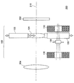
図1は、本発明の一実施形態に係る手振れ補正装置100を備えた撮像装置200を示す模式図である。図1に示すように、撮像装置200は、手振れ補正装置100と、撮像素子202と、光学レンズ204を備えている。光学レンズ204は、被写体像を撮像素子202の撮像面に結像する。撮像素子202は、CCDセンサ、CMOSセンサ等のセンサであり、撮像面に結像した被写体像を光電変換して得られた信号を出力する。
FIG. 1 is a schematic diagram illustrating an
手ぶれ補正装置100は、ユーザが撮像装置200を保持した際の手振れに基づいて、補正レンズ124を光軸210と垂直方向に駆動し、手振れを補正する。手振れ補正装置100は、駆動コイル110、移動マグネット120、レンズ保持枠122、補正レンズ124、ホール素子130、補正コイル140を有して構成される。
The camera
図1において、補正レンズ124は、レンズ保持枠122に保持されている。また、移動マグネット120は、レンズ保持枠122に固定されている。駆動コイル110は、通電されることによって誘導磁気を発生し、磁力によって移動マグネット120を光軸210と垂直な方向へ駆動する。これにより、移動マグネット120が固定されたレンズ保持枠122が補正レンズ124とともに光軸210と垂直方向に移動する。そして、補正レンズ124の移動によって、撮像素子202の撮像面上での被写体像の位置が移動し、手振れを補正することができる。なお、図1では、レンズ保持枠122を垂直方向に駆動するための駆動コイル110及び移動マグネット120のみを図示しているが、レンズ保持枠122を水平方向に駆動するための駆動コイル110及び移動マグネット120が別に設けられている。従って、補正レンズ124を光軸に対して垂直方向と水平方向の2方向に移動させることができ、上下左右の手振れを補正することができる。
In FIG. 1, the
なお、本実施形態では、ユーザによる手ぶれ量に基づいて補正レンズ124を駆動しているが、撮像素子202を光軸と垂直方向に駆動しても良い。この場合、補正レンズ124を設ける必要はなく、移動マグネット120に撮像素子202を装着して撮像素子202を駆動する。
In the present embodiment, the
ホール素子130は、移動マグネット120の移動量を検出する。補正コイル140は、駆動コイル110と逆向きの誘導磁気を発生し、ホール素子130の位置で駆動コイル110の誘導磁気をキャンセルすることで、誘導磁気がホール素子130の出力に与える影響を抑止する。これにより、ホール素子130は、移動マグネット120の位置を正確に検出することができる。なお、本実施形態では、手振れ補正のために駆動される補正レンズ124または撮像素子202の位置を、ホール素子130を用いて検出しているが、MRセンサなど他の磁気センサを用いることも可能である。
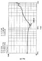
図2は、ホール素子130に発生するコイルからの誘導磁気の影響を説明するための模式図である。駆動コイル110の上部に配置されたホール素子130は、本来的には移動マグネット120の磁気を検知してその位置を正確に検出できるものである。しかし、図2に示すように、補正コイル140を設けていない場合、ホール素子130は、駆動コイル110に流れる電流によって発生する誘導磁気の影響を受けてしまう。図3は、ホール素子130の出力への磁気の影響を測定した結果を示す特性図である。図3において、横軸は周波数を示しており、縦軸は移動マグネット120の実際の移動距離に対するホール素子130の出力の比率を測定した結果を示している。なお、移動マグネット120の実際の移動距離は、レーザセンサ等によって正確に測定することができる。
FIG. 2 is a schematic diagram for explaining the influence of induced magnetism from the coil generated in the
ホール素子は、移動マグネット120の移動距離に比例した値を出力する。従って、本来は、移動マグネット120の実際の移動距離とホール素子130の出力との比率は一定値になる。しかし、図3に示すように、ある周波数(100Hz付近)までは、移動マグネット120の移動距離とホール素子130の出力との比率は一定であるが、周波数130Hz近辺に変曲点があり、周波数が130Hz近辺よりも大きくなると、比率の値が徐々に上昇していることがわかる。
The Hall element outputs a value proportional to the moving distance of the moving
駆動コイル110に流す電流が一定の場合、周波数に対する移動マグネット120の移動量は−40dB/decの傾きで減少し、周波数が100Hz程度では移動マグネット120の移動量が数μm以下となる。このように、周波数が100Hz程度では移動マグネット120の移動量が微小量となり、ホール素子130の本来の出力レベルに対して、駆動コイル110から発生する磁気の影響を受けた場合はホール素子130の出力レベルが大きなってしまうため、図3に示すような特性が現れてしまう。
When the current flowing through the
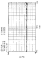
一方、図4は、駆動コイル110の直上または周辺にホール素子130が位置しておらず、ホール素子130が誘導磁気の影響を受けていない場合の結果を比較として示している。図4において、図3と同様に横軸は周波数を示しており、縦軸は移動マグネット120の実際の移動距離に対するホール素子130の出力の比率を示している。この場合、周波数が変化した場合でも、移動マグネット120の移動距離に対するホール素子130の出力の比率は一定であり、図3のような変曲点は生じない。以上のように、誘導磁気の影響を受けると、移動マグネット120の移動距離とホール素子130の出力との比率が変化してしまい、移動量を正確に検出することができなくなる。
On the other hand, FIG. 4 shows a comparison result when the
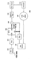
図5は、本実施形態に係る手振れ補正システム300の主要構成を示すブロック図である。図5に示すように、手振れ補正システム300は、ジャイロセンサー302、アンプ304、MCU(マイコン)306、減算部308、サーボフィルタ310、ドライバー回路312、アクチュエータ313(駆動コイル110)、移動マグネット120及びこれによって駆動される補正レンズ124(または撮像素子202)、移動マグネット120の位置を検出するホール素子130、アンプ314を有して構成される。
FIG. 5 is a block diagram illustrating a main configuration of the camera
図5において、ジャイロセンサー302より検知された手振れ振動はアンプ304にて増幅された後、MCU306に入力される。また、駆動する対象である移動マグネット120の位置はホール素子130によって検出され、その検出結果はホール素子130から出力されてアンプ314で増幅された後、MCU306に入力される。
In FIG. 5, the hand vibration detected by the
MCU306は、ジャイロセンサー302で検知された手振れ振動から手振れ量を計算し、手振れを補正するための補正値(手振れ補正値)を算出する。減算部308は、手振れ補正値とホール素子130の位置検出結果を比較し、手振れ補正値からホール素子130の位置検出結果を減算した結果をサーボフィルタ310に入力する。
The
サーボフィルタ310では、適切な制御を行うためのゲインや位相を制御し、ドライバー回路312を通じてアクチュエータ313(駆動コイル110)を駆動し、移動マグネット120を目標の位置へと可動させる。上述したように、サーボフィルタ310には、検知された手振れ量に対して移動マグネット120の位置を減算した結果が入力されるため、手振れ量に対して移動マグネット120の位置を考慮して、必要な目標値に移動マグネット120を駆動する。移動マグネット120が可動した際の位置情報は、ホール素子130にて検知され、再びMCU306からの目標値と比較されてサーボフィルタ310に入力される。このように、本実施形態に係る手振れ補正システム300では、図5中に白線の矢印で示されるサーボループが構成される。サーボループは、ホール素子130の出力がMCU306から出力される手振れ補正値と一致するように、アクチュエータ313を駆動する。
The
このように、手振れ補正システム300では、常にMCU306から算出された目標値(手振れ補正値)と移動マグネット120の現在位置情報とが比較されながら、手振れを補正していくフィードバック制御を行う。手振れ補正性能を高めるためには、このフィードバック制御(サーボループ)の安定化と、手振れ周波数帯域での高いゲインが必要である。従って、誘導磁気の影響度が手振れ補正性能を左右することになる。
As described above, the camera
図6は、図5に示すシステムにおいて、サーボのオープンループ特性のゲインと位相を示す特性図であって、駆動コイル110による誘導磁気の影響が有る場合と無い場合の相違を表している。図6において、ゲインが0dBになる点をゲイン交点といい、ゲイン交点の周波数の位相において−180degとの差分を位相余裕という。さらに位相特性が−180degと交差する周波数におけるゲインの0dBからの低下量をゲイン余裕という。このゲイン余裕と位相余裕の余裕量が少ないほどサーボが不安定となり、発振の原因となる。発振が生じると、移動マグネット120がある周波数で振動した状態となってしまい、適正な手振れ補正を行うことが困難となる。
FIG. 6 is a characteristic diagram showing the gain and phase of the open loop characteristic of the servo in the system shown in FIG. 5, and shows the difference between the case where there is an influence of induction magnetism by the
図6において、ユーザの手ぶれによる周波数は、主として3〜20Hz程度の周波数の振動である。従って、図6に示すように、この周波数帯域でのゲインを十分に大きくすることによって、手振れに対する応答特性が高くなり、移動マグネット120(補正レンズ124)を短時間で且つ高精度に所望の位置に駆動することができる。 In FIG. 6, the frequency due to the hand shake of the user is mainly vibration with a frequency of about 3 to 20 Hz. Therefore, as shown in FIG. 6, by sufficiently increasing the gain in this frequency band, the response characteristic to camera shake is improved, and the moving magnet 120 (correction lens 124) can be moved to a desired position with high accuracy in a short time. Can be driven.
一方、ユーザの手ぶれによる周波数には上述の周波数帯域以外の成分も含まれ、図6に示すように、10Hz〜1kHz以上の程度までの帯域の周波数が図5中のサーボループに混入する。そして、図3で説明したように、一例として100Hz以上の周波数では、ホール素子130の出力に誘導磁気の影響が含まれてしまう。
On the other hand, components other than the above-mentioned frequency band are included in the frequency due to the user's camera shake, and as shown in FIG. 6, frequencies in the band of about 10 Hz to 1 kHz or more are mixed in the servo loop in FIG. As described with reference to FIG. 3, as an example, at a frequency of 100 Hz or higher, the output of the
図6では、100Hz以上の周波数において、誘導磁気の影響がある場合のゲインを破線で示し、誘導磁気の影響が無い場合のゲインを太い実線で示している。図6に示すように、誘導磁気の影響が有る場合は、誘導磁気の影響が無い場合に比べてゲイン余裕量が減り、発振し易くなることがわかる。従って、サーボループに100Hz以上の周波数の振動が混入すると、移動マグネット120が発振してしまい、所望の手振れ補正ができなくなる事態が想定される。
In FIG. 6, the gain when there is an influence of induction magnetism at a frequency of 100 Hz or more is indicated by a broken line, and the gain when there is no influence of induction magnetism is indicated by a thick solid line. As shown in FIG. 6, it can be seen that when there is an influence of induction magnetism, the gain margin amount is reduced compared with a case where there is no influence of induction magnetism, and oscillation tends to occur. Therefore, when vibration with a frequency of 100 Hz or more is mixed in the servo loop, the moving
更に、上述のように手ぶれによる周波数は主として3〜20Hz程度の帯域であるが、手振れ補正にて必要な20Hz以下のゲインを増加しようとすると、ゲイン交点の周波数も増加することになる。しかし、誘導磁気の影響がある場合は、ゲイン交点の周波数を増加すると、ゲイン余裕が減少するため、ゲイン交点の周波数を上げることができない。このため、手振れ補正の応答特性及び位置精度を向上させることに限界が生じてしまう。 Furthermore, as described above, the frequency due to camera shake is mainly in the band of about 3 to 20 Hz. However, if the gain of 20 Hz or less necessary for camera shake correction is increased, the frequency of the gain intersection also increases. However, when there is an influence of induced magnetism, if the gain intersection frequency is increased, the gain margin decreases, so the gain intersection frequency cannot be increased. For this reason, there is a limit in improving response characteristics and position accuracy of camera shake correction.
このため、本実施形態では、図5中のサーボループ内で所定値以上の周波数を検出した場合は、補正コイル140を駆動するようにしている。補正コイル140を駆動することによって、駆動コイル110の誘導磁気をキャンセルすることができるため、図4で説明したように、周波数が高い領域においてもホール素子130からは実際の移動マグネット120の移動量に比例した値が出力される。従って、サーボループにおけるゲイン余裕を増大することが可能となり、発振が生じてしまうことを確実に抑止できる。
For this reason, in the present embodiment, the
図7は、補正コイル140を駆動するための構成を示すブロック図である。図7に示す構成は、図5に示すドライバー回路312とアクチュエータ313のブロックに対応する。図7に示すように、ドライバー回路312の出力は、駆動コイル110と補正回路320へ入力される。駆動コイル110は、ドライバー回路312からの入力に応じて駆動される。
FIG. 7 is a block diagram showing a configuration for driving the
補正回路320は、サーボ帯域において影響を及ぼす周波数帯域(一例として、図3に示す変曲点以上の周波数)の信号を抽出すると、ホール素子130に与える誘導磁気の磁気極性を相殺するため、補正コイル140を駆動する。これにより、誘導磁気がキャンセルされ、ホール素子130は、移動マグネット120の移動による磁界変化分だけを検出することができる。従って、図6における誘導磁気の影響が無い状態と等しくなり、ゲイン余裕が十分に確保された安定なサーボループが実現できる。
When the
補正回路320としては、変曲点以上の周波数帯域を抽出するハイパスフィルター、バンドパスフィルター等を使用することが可能である。補正回路320は、変曲点以上の周波数を検出しない場合は、補正コイル140を駆動しない。従って、この場合は駆動コイル110のみが駆動される。変曲点以下の周波数では、ホール素子130の出力に誘導磁気の影響は生じないため、補正コイル140を駆動しなくても移動マグネット120の正確な位置を検出することが可能である。
As the
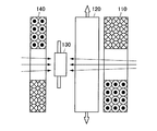
図8及び図9は、駆動コイル110、移動マグネット120、ホール素子130、及び補正コイル140の構成を示す模式図である。駆動コイル110の誘導磁気をキャンセルする方法としては、駆動コイル110と補正コイル140とでコイルの巻き線方向、または回路極性を適合することにより、駆動コイル110の誘導磁気とは逆向きの誘導磁気を補正コイル140から発生させる。
FIG. 8 and FIG. 9 are schematic diagrams showing configurations of the
図8に示す構成例では、駆動コイル110と同じコイルを使用して補正コイル140を構成する。そして、ホール素子130を挟んで、駆動コイル110と補正コイル140を逆向きにして等距離dの位置に配置する。これにより、駆動コイル110と補正コイル140に流れる電流量が同じであれば、駆動コイル110と補正コイル140から同じ誘導磁気が発生する。従って、駆動コイル110と補正コイル140のコイルの巻き線方向を逆向きにすることで、誘導磁気を相殺することが可能である。
In the configuration example shown in FIG. 8, the
また、図9に示す構成例では、スペース効率を考慮して、駆動コイル110よりもサイズの小さい補正コイル140を使用している。図9に示す構成例では、ホール素子130上で誘導磁気をキャンセルできるように補正コイル140の仕様を変更し、ホール素子130と補正コイル140を図8よりも近づけている。この場合は、補正コイル140に流す電流量やコイルの仕様、ホール素子130との距離を最適化することで誘導磁気をキャンセルすることができる。補正コイル140をホール素子130に近づけると、ホール素子130上での補正コイル140の誘導磁気がより大きくなるため、図8よりも小型の補正コイル140を使用することができ、コンパクト化が可能になる。例えば、補正コイル140の巻数を駆動コイル110の巻数よりも少なくすることができる。また、補正コイル140をホール素子130に近づけると、ホール素子130上での補正コイル140の誘導磁気がより大きくなるので、コイル電流を低減することができ、補正コイル140の消費電力を抑えることができる。図9に示す構成例では、補正回路320には、補正コイル140に流す電流量を最適化するためのゲイン調整機能も含まれる。なお、図9の構成例では、補正コイル140をホール素子130に近づけたことにより、移動マグネット120の磁力が補正コイル140に到達していると、補正コイル140によって移動マグネット120を駆動する力が発生する。この場合、駆動コイル110と補正コイル140のコイルの巻き線方向が逆であるため、補正コイル140により移動マグネット120を駆動する力は、駆動コイル110により移動マグネット120を駆動する力と逆方向となり、力が打ち消しあってしまう。このような事態を回避するため、移動マグネット120の補正コイル140側の面には、ヨーク(鉄板)が貼り付けてある(図9において不図示)。これにより、ヨークによって移動マグネット120の磁束が補正コイル側140に漏れることがないため、補正コイル140によって移動マグネット120を駆動する力が発生することを確実に抑止できる。
In the configuration example shown in FIG. 9, the
また、製造上で発生し得るホール素子130上での誘導磁界のばらつきは、駆動コイル110と補正コイル140の間の距離の調整、コイル電流値の調整等によって補うことが可能である。
In addition, variations in the induced magnetic field on the
以上説明したように本実施形態によれば、サーボループ内でホール素子130の出力に誘導磁気の影響が現れる周波数を検出した場合は、補正コイル140を駆動して誘導磁気をキャンセルするようにしたため、移動マグネット120の位置を高精度に検出することが可能となる。従って、手振れ補正システムにおいて、サーボループを安定して制御することが可能となり、サーボが発振してしまうことを確実に抑止することが可能となる。
As described above, according to the present embodiment, when the frequency at which the influence of the induction magnetism appears on the output of the
以上、添付図面を参照しながら本発明の好適な実施形態について詳細に説明したが、本発明はかかる例に限定されない。本発明の属する技術の分野における通常の知識を有する者であれば、特許請求の範囲に記載された技術的思想の範疇内において、各種の変更例または修正例に想到し得ることは明らかであり、これらについても、当然に本発明の技術的範囲に属するものと了解される。 The preferred embodiments of the present invention have been described in detail above with reference to the accompanying drawings, but the present invention is not limited to such examples. It is obvious that a person having ordinary knowledge in the technical field to which the present invention pertains can come up with various changes or modifications within the scope of the technical idea described in the claims. Of course, it is understood that these also belong to the technical scope of the present invention.
100 手振れ補正装置
110 駆動コイル
120 移動マグネット
124 補正レンズ
130 ホール素子
140 補正コイル
200 撮像装置
202 撮像素子
320 補正回路
DESCRIPTION OF
Claims (10)
前記移動部材の位置を検出する磁気センサと、
磁気コイルを有し、前記磁気センサを間に介在させて前記駆動アクチュエータと対向配置される補正用アクチュエータと、
前記駆動アクチュエータの駆動信号に所定値以上の周波数成分が含まれている場合に前記補正用アクチュエータを駆動する駆動回路と、
を備えることを特徴とする、手振れ補正装置。 A drive actuator having a magnetic coil and driving a moving member for correcting camera shake by magnetic force;
A magnetic sensor for detecting the position of the moving member;
A correction actuator having a magnetic coil and disposed opposite to the drive actuator with the magnetic sensor interposed therebetween;
A drive circuit that drives the correction actuator when the drive signal of the drive actuator includes a frequency component equal to or higher than a predetermined value;
A camera shake correction device comprising:
前記補正用アクチュエータの前記磁気コイルは、前記駆動アクチュエータの前記磁気コイルと同一の仕様であり、コイルの巻き方向が逆方向であることを特徴とする、請求項1に記載の手振れ補正装置。 The drive actuator and the correction actuator are arranged at equidistant positions from the magnetic sensor,
The camera shake correction device according to claim 1, wherein the magnetic coil of the correction actuator has the same specifications as the magnetic coil of the drive actuator, and a winding direction of the coil is reverse.
磁気コイルを有し、手振れ補正のための補正レンズ又は前記撮像素子を磁力により駆動する駆動アクチュエータと、
前記補正レンズ又は前記撮像素子とともに駆動される磁石の位置を検出する磁気センサと、
磁気コイルを有し、前記磁気センサを間に介在させて前記駆動アクチュエータと対向配置される補正用アクチュエータと、
前記駆動アクチュエータの駆動信号に所定値以上の周波数成分が含まれている場合に前記補正用アクチュエータを駆動する駆動回路と、
を備えることを特徴とする、撮像装置。 An image sensor on which a subject image is formed;
A correction lens for correcting camera shake or a drive actuator for driving the image sensor with a magnetic force, and a magnetic coil;
A magnetic sensor for detecting a position of a magnet driven together with the correction lens or the imaging element;
A correction actuator having a magnetic coil and disposed opposite to the drive actuator with the magnetic sensor interposed therebetween;
A drive circuit that drives the correction actuator when the drive signal of the drive actuator includes a frequency component equal to or higher than a predetermined value;
An imaging apparatus comprising:
前記補正用アクチュエータの前記磁気コイルは、前記駆動アクチュエータの前記磁気コイルと同一の仕様であり、コイルの巻き方向が逆方向であることを特徴とする、請求項6に記載の撮像装置。 The drive actuator and the correction actuator are arranged at equidistant positions from the magnetic sensor,
The imaging apparatus according to claim 6, wherein the magnetic coil of the correction actuator has the same specifications as the magnetic coil of the drive actuator, and a winding direction of the coil is reverse.
Priority Applications (1)
| Application Number | Priority Date | Filing Date | Title |
|---|---|---|---|
| JP2011051060A JP2012189657A (en) | 2011-03-09 | 2011-03-09 | Camera shake correction device and imaging apparatus |
Applications Claiming Priority (1)
| Application Number | Priority Date | Filing Date | Title |
|---|---|---|---|
| JP2011051060A JP2012189657A (en) | 2011-03-09 | 2011-03-09 | Camera shake correction device and imaging apparatus |
Publications (1)
| Publication Number | Publication Date |
|---|---|
| JP2012189657A true JP2012189657A (en) | 2012-10-04 |
Family
ID=47082920
Family Applications (1)
| Application Number | Title | Priority Date | Filing Date |
|---|---|---|---|
| JP2011051060A Withdrawn JP2012189657A (en) | 2011-03-09 | 2011-03-09 | Camera shake correction device and imaging apparatus |
Country Status (1)
| Country | Link |
|---|---|
| JP (1) | JP2012189657A (en) |
Cited By (2)
| Publication number | Priority date | Publication date | Assignee | Title |
|---|---|---|---|---|
| JP2016151738A (en) * | 2015-02-19 | 2016-08-22 | ルネサスエレクトロニクス株式会社 | Semiconductor device, correction method in semiconductor device and correction method in camera module |
| JP2018205585A (en) * | 2017-06-07 | 2018-12-27 | 日本電産サンキョー株式会社 | Optical unit with tremor correction function |
-
2011
- 2011-03-09 JP JP2011051060A patent/JP2012189657A/en not_active Withdrawn
Cited By (2)
| Publication number | Priority date | Publication date | Assignee | Title |
|---|---|---|---|---|
| JP2016151738A (en) * | 2015-02-19 | 2016-08-22 | ルネサスエレクトロニクス株式会社 | Semiconductor device, correction method in semiconductor device and correction method in camera module |
| JP2018205585A (en) * | 2017-06-07 | 2018-12-27 | 日本電産サンキョー株式会社 | Optical unit with tremor correction function |
Similar Documents
| Publication | Publication Date | Title |
|---|---|---|
| CN105814484B (en) | Shake correction device and adjustment method thereof, shake correction circuit, shake correction method, and position control method of camera module and optical element thereof | |
| CN101957535B (en) | Anti-vibration actuator, and lens unit and camera equipped with same | |
| US20140368936A1 (en) | Lens driving device with an improved ois coil structure | |
| JP6769696B2 (en) | Position detector | |
| US20180205862A1 (en) | Drive device and method for controlling the drive device | |
| JP5884242B2 (en) | Actuator, lens unit, and camera | |
| JP2009151028A (en) | Vibration correction control circuit and imaging apparatus equipped with the same | |
| JP5718102B2 (en) | Position detection apparatus and imaging apparatus | |
| JP6303382B2 (en) | Drive control device, imaging device, and drive control method | |
| JP6930049B2 (en) | Control method of drive device and image pickup device | |
| JP5441150B2 (en) | DRIVE CONTROL DEVICE, DRIVE CONTROL METHOD, AND IMAGING DEVICE | |
| KR101329741B1 (en) | Method of control of hand-shaking correction and Apparatus of control hand-shaking correction | |
| JP2009163153A (en) | Lens actuator | |
| KR20170062196A (en) | Image stabilization device | |
| JP2017021222A (en) | Optical system drive unit and camera module | |
| JP2013050499A (en) | Optical image shake correction mechanism | |
| JP2009152792A (en) | Vibration correction control circuit and imaging apparatus equipped with the same | |
| JP5882585B2 (en) | Image blur correction apparatus, optical apparatus, and control method thereof | |
| JP5707801B2 (en) | Imaging apparatus and electronic apparatus | |
| JP2015106125A (en) | Camera-shake correction device | |
| JP2008250156A (en) | camera | |
| JP2018004859A (en) | Actuator, and lens unit equipped with the same, and camera equipped therewith | |
| JP2010210908A (en) | Shake correction device and optical equipment | |
| JP2014228621A (en) | Camera-shake correcting device and photographing apparatus | |
| JP2008292902A (en) | Image shake correction apparatus and imaging apparatus |
Legal Events
| Date | Code | Title | Description |
|---|---|---|---|
| A300 | Application deemed to be withdrawn because no request for examination was validly filed |
Free format text: JAPANESE INTERMEDIATE CODE: A300 Effective date: 20140513 |