JP2012190621A - コネクタ - Google Patents
コネクタ Download PDFInfo
- Publication number
- JP2012190621A JP2012190621A JP2011052210A JP2011052210A JP2012190621A JP 2012190621 A JP2012190621 A JP 2012190621A JP 2011052210 A JP2011052210 A JP 2011052210A JP 2011052210 A JP2011052210 A JP 2011052210A JP 2012190621 A JP2012190621 A JP 2012190621A
- Authority
- JP
- Japan
- Prior art keywords
- support groove
- metal fitting
- hole
- cable
- pressed
- Prior art date
- Legal status (The legal status is an assumption and is not a legal conclusion. Google has not performed a legal analysis and makes no representation as to the accuracy of the status listed.)
- Granted
Links
Images




Classifications
-
- H—ELECTRICITY
- H01—ELECTRIC ELEMENTS
- H01R—ELECTRICALLY-CONDUCTIVE CONNECTIONS; STRUCTURAL ASSOCIATIONS OF A PLURALITY OF MUTUALLY-INSULATED ELECTRICAL CONNECTING ELEMENTS; COUPLING DEVICES; CURRENT COLLECTORS
- H01R12/00—Structural associations of a plurality of mutually-insulated electrical connecting elements, specially adapted for printed circuits, e.g. printed circuit boards [PCB], flat or ribbon cables, or like generally planar structures, e.g. terminal strips, terminal blocks; Coupling devices specially adapted for printed circuits, flat or ribbon cables, or like generally planar structures; Terminals specially adapted for contact with, or insertion into, printed circuits, flat or ribbon cables, or like generally planar structures
- H01R12/70—Coupling devices
- H01R12/77—Coupling devices for flexible printed circuits, flat or ribbon cables or like structures
- H01R12/79—Coupling devices for flexible printed circuits, flat or ribbon cables or like structures connecting to rigid printed circuits or like structures
-
- H—ELECTRICITY
- H01—ELECTRIC ELEMENTS
- H01R—ELECTRICALLY-CONDUCTIVE CONNECTIONS; STRUCTURAL ASSOCIATIONS OF A PLURALITY OF MUTUALLY-INSULATED ELECTRICAL CONNECTING ELEMENTS; COUPLING DEVICES; CURRENT COLLECTORS
- H01R13/00—Details of coupling devices of the kinds covered by groups H01R12/70 or H01R24/00 - H01R33/00
- H01R13/40—Securing contact members in or to a base or case; Insulating of contact members
- H01R13/405—Securing in non-demountable manner, e.g. moulding, riveting
- H01R13/41—Securing in non-demountable manner, e.g. moulding, riveting by frictional grip in grommet, panel or base
-
- H—ELECTRICITY
- H01—ELECTRIC ELEMENTS
- H01R—ELECTRICALLY-CONDUCTIVE CONNECTIONS; STRUCTURAL ASSOCIATIONS OF A PLURALITY OF MUTUALLY-INSULATED ELECTRICAL CONNECTING ELEMENTS; COUPLING DEVICES; CURRENT COLLECTORS
- H01R13/00—Details of coupling devices of the kinds covered by groups H01R12/70 or H01R24/00 - H01R33/00
- H01R13/58—Means for relieving strain on wire connection, e.g. cord grip, for avoiding loosening of connections between wires and terminals within a coupling device terminating a cable
- H01R13/5804—Means for relieving strain on wire connection, e.g. cord grip, for avoiding loosening of connections between wires and terminals within a coupling device terminating a cable comprising a separate cable clamping part
- H01R13/5808—Means for relieving strain on wire connection, e.g. cord grip, for avoiding loosening of connections between wires and terminals within a coupling device terminating a cable comprising a separate cable clamping part formed by a metallic element crimped around the cable
-
- H—ELECTRICITY
- H01—ELECTRIC ELEMENTS
- H01R—ELECTRICALLY-CONDUCTIVE CONNECTIONS; STRUCTURAL ASSOCIATIONS OF A PLURALITY OF MUTUALLY-INSULATED ELECTRICAL CONNECTING ELEMENTS; COUPLING DEVICES; CURRENT COLLECTORS
- H01R4/00—Electrically-conductive connections between two or more conductive members in direct contact, i.e. touching one another; Means for effecting or maintaining such contact; Electrically-conductive connections having two or more spaced connecting locations for conductors and using contact members penetrating insulation
- H01R4/10—Electrically-conductive connections between two or more conductive members in direct contact, i.e. touching one another; Means for effecting or maintaining such contact; Electrically-conductive connections having two or more spaced connecting locations for conductors and using contact members penetrating insulation effected solely by twisting, wrapping, bending, crimping, or other permanent deformation
- H01R4/18—Electrically-conductive connections between two or more conductive members in direct contact, i.e. touching one another; Means for effecting or maintaining such contact; Electrically-conductive connections having two or more spaced connecting locations for conductors and using contact members penetrating insulation effected solely by twisting, wrapping, bending, crimping, or other permanent deformation by crimping
- H01R4/183—Electrically-conductive connections between two or more conductive members in direct contact, i.e. touching one another; Means for effecting or maintaining such contact; Electrically-conductive connections having two or more spaced connecting locations for conductors and using contact members penetrating insulation effected solely by twisting, wrapping, bending, crimping, or other permanent deformation by crimping for cylindrical elongated bodies, e.g. cables having circular cross-section
Landscapes
- Details Of Connecting Devices For Male And Female Coupling (AREA)
- Coupling Device And Connection With Printed Circuit (AREA)
Abstract
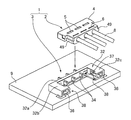
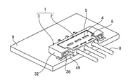
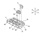
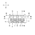
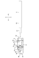
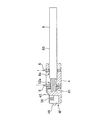
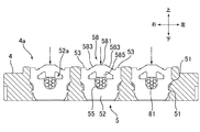
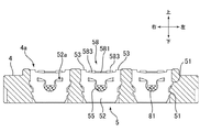
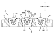
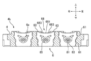
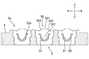
【解決手段】本発明のコネクタにおいて、挿入穴4dに挿入されたケーブル8は、支持溝4bに収容された金具6の貫通穴6aに挿入される。支持溝4bに収容された金具6は、支持溝4bの深さ方向に押圧されることで、貫通穴6aの大きさが減少するように塑性変形する。
【選択図】図7A
Description
Claims (10)
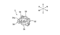
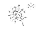
- 貫通穴が形成された金具と、
前記金具が収容される支持溝であって、少なくとも前記貫通穴の貫通方向への前記金具の変位を制限する支持溝と、ケーブルが挿入される挿入穴であって、前記支持溝に連続し、前記挿入穴に挿入されたケーブルが、前記支持溝に収容された前記金具の貫通穴に挿入される挿入穴と、が形成された筐体と、
を備え、
前記支持溝に収容された前記金具は、前記支持溝の深さ方向に押圧されることで、前記貫通穴の大きさが減少するように塑性変形する、
ことを特徴とするコネクタ。 - 前記金具は、前記支持溝の深さ方向と逆方向であって、前記貫通穴から離れる方向に突出した被押圧部を有する、
請求項1に記載のコネクタ。 - 前記被押圧部は、前記貫通穴の縁が前記支持溝の深さ方向に突出し、前記ケーブルと接触する門歯部を含む、
請求項2に記載のコネクタ。 - 前記貫通穴の縁のうち前記門歯部に対向する部分に、前記ケーブルの外形に沿って湾曲した受け部が形成される、
請求項3に記載のコネクタ。 - 前記金具は、前記被押圧部に対して前記支持溝の幅方向の両側に、前記支持溝の深さ方向と逆方向に突出した突出部を有する、
請求項2ないし4の何れかに記載のコネクタ。 - 前記金具は、折り曲げられた金属板からなる端子であり、
前記被押圧部を有し、前記貫通穴が形成された第1の板部と、相手方の端子と接触する接触部を有し、前記貫通穴が形成された第2の板部と、を備え、
前記第1の板部と前記第2の板部とが前記貫通穴同士が連続するように重ねられる、
請求項2ないし5の何れかに記載のコネクタ。 - 前記金具は、前記ケーブルの絶縁性の外皮と接触する金具である、
請求項1ないし5の何れかに記載のコネクタ。 - 前記被押圧部は、前記貫通穴の縁が前記支持溝の深さ方向に突出した門歯部を含み、
前記被押圧部が前記支持溝の深さ方向に押圧されることで、前記門歯部が前記ケーブルの絶縁性の外皮を切断し、内部の金属線と接触する、
請求項2ないし5の何れかに記載のコネクタ。 - 貫通穴が形成された第1の金具と、
貫通穴が形成された第2の金具と、
前記第1の金具が収容される第1の支持溝であって、少なくとも前記貫通穴の貫通方向への前記第1の金具の変位を制限する第1の支持溝と、前記第2の金具が収容される第2の支持溝であって、少なくとも前記貫通穴の貫通方向への前記第2の金具の変位を制限する第2の支持溝と、ケーブルが挿入される挿入穴であって、前記第1の支持溝及び前記第2の支持溝に連続し、前記挿入穴に挿入されたケーブルが、前記第1の支持溝に収容された前記第1の金具の貫通穴及び前記第2の支持溝に収容された前記第2の金具の貫通穴にこの順に挿入される挿入穴と、が形成された筐体と、
を備え、
前記第1の支持溝に収容された前記第1の金具は、前記第1の支持溝の深さ方向に押圧されることで、前記貫通穴の大きさが減少するように塑性変形し、前記ケーブルの絶縁性の外皮と接触し、
前記第2の支持溝に収容された前記第2の金具は、前記第2の支持溝の深さ方向に押圧されることで、前記貫通穴の大きさが減少するように塑性変形し、前記ケーブルの先端部に露出した金属線と接触する、
ことを特徴とするコネクタ。 - 前記ケーブルは、同軸ケーブルであり、
貫通穴が形成された第3の金具をさらに備え、
前記筐体には、前記第3の金具が収容される第3の支持溝であって、前記第1の支持溝と前記第2の支持溝の間に位置し、前記挿入穴と連続する、少なくとも前記貫通穴の貫通方向への前記第3の金具の変位を制限する第3の支持溝がさらに形成され、
前記第3の支持溝に収容された前記第3の金具は、前記第3の支持溝の深さ方向に押圧されることで、前記貫通穴の大きさが減少するように塑性変形し、前記同軸ケーブルの先端部に露出した金属線と絶縁性の外皮との間に露出した外部導体と接触する、
請求項9に記載のコネクタ。
Priority Applications (4)
| Application Number | Priority Date | Filing Date | Title |
|---|---|---|---|
| JP2011052210A JP5700807B2 (ja) | 2011-03-09 | 2011-03-09 | コネクタ |
| CN2012201012360U CN202444078U (zh) | 2011-03-09 | 2012-03-09 | 连接器 |
| TW101204329U TWM460445U (zh) | 2011-03-09 | 2012-03-09 | 連接器 |
| US13/416,124 US8636539B2 (en) | 2011-03-09 | 2012-03-09 | Connector |
Applications Claiming Priority (1)
| Application Number | Priority Date | Filing Date | Title |
|---|---|---|---|
| JP2011052210A JP5700807B2 (ja) | 2011-03-09 | 2011-03-09 | コネクタ |
Publications (2)
| Publication Number | Publication Date |
|---|---|
| JP2012190621A true JP2012190621A (ja) | 2012-10-04 |
| JP5700807B2 JP5700807B2 (ja) | 2015-04-15 |
Family
ID=46795983
Family Applications (1)
| Application Number | Title | Priority Date | Filing Date |
|---|---|---|---|
| JP2011052210A Expired - Fee Related JP5700807B2 (ja) | 2011-03-09 | 2011-03-09 | コネクタ |
Country Status (4)
| Country | Link |
|---|---|
| US (1) | US8636539B2 (ja) |
| JP (1) | JP5700807B2 (ja) |
| CN (1) | CN202444078U (ja) |
| TW (1) | TWM460445U (ja) |
Families Citing this family (3)
| Publication number | Priority date | Publication date | Assignee | Title |
|---|---|---|---|---|
| CN103515761B (zh) * | 2012-06-19 | 2015-11-25 | 凡甲电子(苏州)有限公司 | 电连接器组件 |
| DE102015111675A1 (de) * | 2015-07-17 | 2017-01-19 | Wago Verwaltungsgesellschaft Mbh | Steckverbinder und Verformungswerkzeug hierzu |
| CN110571588B (zh) * | 2019-10-16 | 2024-09-17 | 常熟市斯佳登电器有限公司 | 一种插头用压线装置 |
Citations (4)
| Publication number | Priority date | Publication date | Assignee | Title |
|---|---|---|---|---|
| JPH0640499B2 (ja) * | 1989-04-14 | 1994-05-25 | 株式会社茂治 | コネクタにおけるクランプ金具 |
| JP2001176603A (ja) * | 1999-12-15 | 2001-06-29 | Sumitomo Wiring Syst Ltd | コネクタ |
| JP2001351727A (ja) * | 2000-06-06 | 2001-12-21 | Sumitomo Wiring Syst Ltd | コネクタ |
| JP2005108650A (ja) * | 2003-09-30 | 2005-04-21 | Jst Mfg Co Ltd | 電気コネクタ |
Family Cites Families (8)
| Publication number | Priority date | Publication date | Assignee | Title |
|---|---|---|---|---|
| US2600012A (en) * | 1946-06-27 | 1952-06-10 | Aircraft Marine Prod Inc | Electrical connector |
| US3612747A (en) * | 1969-02-14 | 1971-10-12 | Shlesinger Jr Bernard E | Nonstrip connector for insulated electrical conductors and electrical conductors therefor |
| US3728473A (en) * | 1971-10-06 | 1973-04-17 | Thomas & Betts Corp | Multi-orificed electrical connector |
| US3912853A (en) * | 1974-08-08 | 1975-10-14 | Plessey Inc | High dielectric strength cable connector |
| US4191442A (en) * | 1978-05-25 | 1980-03-04 | Panduit Corp. | Electrical connector and method of fabricating a wire harness using the connector |
| US5125851A (en) * | 1991-09-23 | 1992-06-30 | Molex Incorporated | Insulation displacement terminal for an electrical connector |
| JPH0640499A (ja) | 1992-07-15 | 1994-02-15 | Sharp Corp | 配送管中の漏洩検知装置 |
| US5658163A (en) * | 1995-12-19 | 1997-08-19 | Molex Incorporated | Terminal for connecting electrical wires |
-
2011
- 2011-03-09 JP JP2011052210A patent/JP5700807B2/ja not_active Expired - Fee Related
-
2012
- 2012-03-09 TW TW101204329U patent/TWM460445U/zh not_active IP Right Cessation
- 2012-03-09 CN CN2012201012360U patent/CN202444078U/zh not_active Expired - Fee Related
- 2012-03-09 US US13/416,124 patent/US8636539B2/en not_active Expired - Fee Related
Patent Citations (4)
| Publication number | Priority date | Publication date | Assignee | Title |
|---|---|---|---|---|
| JPH0640499B2 (ja) * | 1989-04-14 | 1994-05-25 | 株式会社茂治 | コネクタにおけるクランプ金具 |
| JP2001176603A (ja) * | 1999-12-15 | 2001-06-29 | Sumitomo Wiring Syst Ltd | コネクタ |
| JP2001351727A (ja) * | 2000-06-06 | 2001-12-21 | Sumitomo Wiring Syst Ltd | コネクタ |
| JP2005108650A (ja) * | 2003-09-30 | 2005-04-21 | Jst Mfg Co Ltd | 電気コネクタ |
Also Published As
| Publication number | Publication date |
|---|---|
| JP5700807B2 (ja) | 2015-04-15 |
| TWM460445U (zh) | 2013-08-21 |
| US20120231660A1 (en) | 2012-09-13 |
| US8636539B2 (en) | 2014-01-28 |
| CN202444078U (zh) | 2012-09-19 |
Similar Documents
| Publication | Publication Date | Title |
|---|---|---|
| CN108879146B (zh) | 浮动连接器 | |
| KR101653437B1 (ko) | 동축 커넥터 및 그 조립방법 | |
| JP5112383B2 (ja) | モジュラープラグ | |
| US9583889B2 (en) | Cable connector assembly having improved metal shell | |
| TW201014062A (en) | Electric connector | |
| TW200841528A (en) | Connector | |
| KR100851709B1 (ko) | 전기 커넥터 | |
| JP2012129082A (ja) | コネクタ | |
| JP4394708B2 (ja) | 同軸コネクタ | |
| JP6961433B2 (ja) | オス型端子、オスコネクタ及び接続構造体 | |
| JP4883726B2 (ja) | モジュラープラグ | |
| JP6393915B2 (ja) | コネクタ | |
| JP5700807B2 (ja) | コネクタ | |
| JP2007193949A (ja) | コネクタ | |
| JP2012038713A (ja) | シールドコネクタ | |
| CN101872928B (zh) | 带外部导体保持器的电连接器以及屏蔽电缆束 | |
| JP5289154B2 (ja) | コネクタ | |
| JP2006286223A (ja) | シールドコネクタ | |
| JP5027893B2 (ja) | ヘッダー | |
| JP6039487B2 (ja) | コネクタ | |
| JP2005209540A (ja) | 圧接型コンタクト、これを用いたコネクタおよび電線付きコネクタ、ならびに電線付きコネクタの製造方法 | |
| US20060116020A1 (en) | Electric connector | |
| JP2000299167A (ja) | 電気コネクタ | |
| JP2012018779A (ja) | コネクタ | |
| JP2015053218A (ja) | コネクタおよびワイヤーハーネス |
Legal Events
| Date | Code | Title | Description |
|---|---|---|---|
| A621 | Written request for application examination |
Free format text: JAPANESE INTERMEDIATE CODE: A621 Effective date: 20131125 |
|
| A131 | Notification of reasons for refusal |
Free format text: JAPANESE INTERMEDIATE CODE: A131 Effective date: 20140902 |
|
| A521 | Request for written amendment filed |
Free format text: JAPANESE INTERMEDIATE CODE: A523 Effective date: 20141007 |
|
| TRDD | Decision of grant or rejection written | ||
| A01 | Written decision to grant a patent or to grant a registration (utility model) |
Free format text: JAPANESE INTERMEDIATE CODE: A01 Effective date: 20150210 |
|
| A61 | First payment of annual fees (during grant procedure) |
Free format text: JAPANESE INTERMEDIATE CODE: A61 Effective date: 20150216 |
|
| R150 | Certificate of patent or registration of utility model |
Ref document number: 5700807 Country of ref document: JP Free format text: JAPANESE INTERMEDIATE CODE: R150 |
|
| S533 | Written request for registration of change of name |
Free format text: JAPANESE INTERMEDIATE CODE: R313533 |
|
| R350 | Written notification of registration of transfer |
Free format text: JAPANESE INTERMEDIATE CODE: R350 |
|
| R250 | Receipt of annual fees |
Free format text: JAPANESE INTERMEDIATE CODE: R250 |
|
| R250 | Receipt of annual fees |
Free format text: JAPANESE INTERMEDIATE CODE: R250 |
|
| R250 | Receipt of annual fees |
Free format text: JAPANESE INTERMEDIATE CODE: R250 |
|
| R250 | Receipt of annual fees |
Free format text: JAPANESE INTERMEDIATE CODE: R250 |
|
| R250 | Receipt of annual fees |
Free format text: JAPANESE INTERMEDIATE CODE: R250 |
|
| R250 | Receipt of annual fees |
Free format text: JAPANESE INTERMEDIATE CODE: R250 |
|
| R250 | Receipt of annual fees |
Free format text: JAPANESE INTERMEDIATE CODE: R250 |
|
| LAPS | Cancellation because of no payment of annual fees |