JP2012201769A - Rapid heatup method for organic matter gasification system - Google Patents
Rapid heatup method for organic matter gasification system Download PDFInfo
- Publication number
- JP2012201769A JP2012201769A JP2011066792A JP2011066792A JP2012201769A JP 2012201769 A JP2012201769 A JP 2012201769A JP 2011066792 A JP2011066792 A JP 2011066792A JP 2011066792 A JP2011066792 A JP 2011066792A JP 2012201769 A JP2012201769 A JP 2012201769A
- Authority
- JP
- Japan
- Prior art keywords
- temperature
- preheater
- heat carrier
- reformer
- hot air
- Prior art date
- Legal status (The legal status is an assumption and is not a legal conclusion. Google has not performed a legal analysis and makes no representation as to the accuracy of the status listed.)
- Pending
Links
- 238000002309 gasification Methods 0.000 title claims abstract description 41
- 238000000034 method Methods 0.000 title claims abstract description 40
- 239000005416 organic matter Substances 0.000 title description 2
- 239000002994 raw material Substances 0.000 claims abstract description 78
- 238000010438 heat treatment Methods 0.000 claims abstract description 60
- 239000011368 organic material Substances 0.000 claims abstract description 47
- 239000007789 gas Substances 0.000 claims description 79
- 230000007423 decrease Effects 0.000 claims description 23
- 238000000197 pyrolysis Methods 0.000 claims description 22
- XLYOFNOQVPJJNP-UHFFFAOYSA-N water Chemical compound O XLYOFNOQVPJJNP-UHFFFAOYSA-N 0.000 claims description 20
- 239000000126 substance Substances 0.000 claims description 19
- 238000001816 cooling Methods 0.000 claims description 15
- 238000012546 transfer Methods 0.000 claims description 15
- 239000000969 carrier Substances 0.000 claims description 11
- 229910052739 hydrogen Inorganic materials 0.000 claims description 8
- 239000001257 hydrogen Substances 0.000 claims description 8
- 238000000629 steam reforming Methods 0.000 claims description 8
- 230000001629 suppression Effects 0.000 claims description 8
- UFHFLCQGNIYNRP-UHFFFAOYSA-N Hydrogen Chemical compound [H][H] UFHFLCQGNIYNRP-UHFFFAOYSA-N 0.000 claims description 7
- 238000012805 post-processing Methods 0.000 claims description 7
- 230000000630 rising effect Effects 0.000 claims description 7
- 230000003247 decreasing effect Effects 0.000 claims description 6
- 238000012423 maintenance Methods 0.000 claims description 2
- 239000007787 solid Substances 0.000 description 48
- 239000002956 ash Substances 0.000 description 40
- 239000000428 dust Substances 0.000 description 19
- 239000002245 particle Substances 0.000 description 15
- 238000007664 blowing Methods 0.000 description 14
- 239000000446 fuel Substances 0.000 description 14
- 230000000694 effects Effects 0.000 description 13
- 238000009413 insulation Methods 0.000 description 13
- 238000002485 combustion reaction Methods 0.000 description 12
- 230000005540 biological transmission Effects 0.000 description 9
- 230000005855 radiation Effects 0.000 description 9
- 238000009826 distribution Methods 0.000 description 8
- 238000000926 separation method Methods 0.000 description 7
- 238000005979 thermal decomposition reaction Methods 0.000 description 7
- 230000005611 electricity Effects 0.000 description 6
- 239000002184 metal Substances 0.000 description 6
- 229910052751 metal Inorganic materials 0.000 description 6
- 238000006243 chemical reaction Methods 0.000 description 5
- 238000004519 manufacturing process Methods 0.000 description 5
- 239000000463 material Substances 0.000 description 5
- 238000013021 overheating Methods 0.000 description 5
- 239000011343 solid material Substances 0.000 description 5
- TVZRAEYQIKYCPH-UHFFFAOYSA-N 3-(trimethylsilyl)propane-1-sulfonic acid Chemical compound C[Si](C)(C)CCCS(O)(=O)=O TVZRAEYQIKYCPH-UHFFFAOYSA-N 0.000 description 4
- 239000002028 Biomass Substances 0.000 description 4
- XEEYBQQBJWHFJM-UHFFFAOYSA-N Iron Chemical compound [Fe] XEEYBQQBJWHFJM-UHFFFAOYSA-N 0.000 description 4
- 238000009825 accumulation Methods 0.000 description 4
- PNEYBMLMFCGWSK-UHFFFAOYSA-N aluminium oxide Inorganic materials [O-2].[O-2].[O-2].[Al+3].[Al+3] PNEYBMLMFCGWSK-UHFFFAOYSA-N 0.000 description 4
- 239000000919 ceramic Substances 0.000 description 4
- 230000006698 induction Effects 0.000 description 4
- 230000002093 peripheral effect Effects 0.000 description 4
- 238000006057 reforming reaction Methods 0.000 description 4
- 239000002918 waste heat Substances 0.000 description 4
- 239000000498 cooling water Substances 0.000 description 3
- 238000005265 energy consumption Methods 0.000 description 3
- 238000001704 evaporation Methods 0.000 description 3
- 230000008020 evaporation Effects 0.000 description 3
- 238000012545 processing Methods 0.000 description 3
- 238000004080 punching Methods 0.000 description 3
- 239000002699 waste material Substances 0.000 description 3
- OKTJSMMVPCPJKN-UHFFFAOYSA-N Carbon Chemical compound [C] OKTJSMMVPCPJKN-UHFFFAOYSA-N 0.000 description 2
- 229910000990 Ni alloy Inorganic materials 0.000 description 2
- 229910052799 carbon Inorganic materials 0.000 description 2
- 229910010293 ceramic material Inorganic materials 0.000 description 2
- 238000004140 cleaning Methods 0.000 description 2
- 230000008021 deposition Effects 0.000 description 2
- 238000005338 heat storage Methods 0.000 description 2
- 239000011261 inert gas Substances 0.000 description 2
- 229910052742 iron Inorganic materials 0.000 description 2
- 238000005259 measurement Methods 0.000 description 2
- 239000000203 mixture Substances 0.000 description 2
- 239000004033 plastic Substances 0.000 description 2
- 229920003023 plastic Polymers 0.000 description 2
- -1 polypropylene Polymers 0.000 description 2
- 238000010248 power generation Methods 0.000 description 2
- 239000012429 reaction media Substances 0.000 description 2
- 238000002407 reforming Methods 0.000 description 2
- 238000007873 sieving Methods 0.000 description 2
- 238000007711 solidification Methods 0.000 description 2
- 230000008023 solidification Effects 0.000 description 2
- 238000003860 storage Methods 0.000 description 2
- 238000005406 washing Methods 0.000 description 2
- 239000002023 wood Substances 0.000 description 2
- 235000002918 Fraxinus excelsior Nutrition 0.000 description 1
- 239000004698 Polyethylene Substances 0.000 description 1
- 239000004743 Polypropylene Substances 0.000 description 1
- 239000004793 Polystyrene Substances 0.000 description 1
- BZHJMEDXRYGGRV-UHFFFAOYSA-N Vinyl chloride Chemical compound ClC=C BZHJMEDXRYGGRV-UHFFFAOYSA-N 0.000 description 1
- 230000002159 abnormal effect Effects 0.000 description 1
- 238000013459 approach Methods 0.000 description 1
- 230000000903 blocking effect Effects 0.000 description 1
- 239000012876 carrier material Substances 0.000 description 1
- 238000009833 condensation Methods 0.000 description 1
- 230000005494 condensation Effects 0.000 description 1
- 238000007599 discharging Methods 0.000 description 1
- 238000005516 engineering process Methods 0.000 description 1
- 238000000605 extraction Methods 0.000 description 1
- 239000002803 fossil fuel Substances 0.000 description 1
- 239000008187 granular material Substances 0.000 description 1
- 150000002431 hydrogen Chemical class 0.000 description 1
- 238000009434 installation Methods 0.000 description 1
- 239000007788 liquid Substances 0.000 description 1
- 239000000113 methacrylic resin Substances 0.000 description 1
- 229920000573 polyethylene Polymers 0.000 description 1
- 229920001155 polypropylene Polymers 0.000 description 1
- 229920002223 polystyrene Polymers 0.000 description 1
- 229920002635 polyurethane Polymers 0.000 description 1
- 239000004814 polyurethane Substances 0.000 description 1
- 230000002035 prolonged effect Effects 0.000 description 1
- 230000000717 retained effect Effects 0.000 description 1
- 230000002441 reversible effect Effects 0.000 description 1
- 238000007790 scraping Methods 0.000 description 1
- 238000012216 screening Methods 0.000 description 1
- 239000007921 spray Substances 0.000 description 1
- 238000010998 test method Methods 0.000 description 1
- 230000007704 transition Effects 0.000 description 1
- 238000010792 warming Methods 0.000 description 1
- 238000004065 wastewater treatment Methods 0.000 description 1
Images

Classifications
-
- Y—GENERAL TAGGING OF NEW TECHNOLOGICAL DEVELOPMENTS; GENERAL TAGGING OF CROSS-SECTIONAL TECHNOLOGIES SPANNING OVER SEVERAL SECTIONS OF THE IPC; TECHNICAL SUBJECTS COVERED BY FORMER USPC CROSS-REFERENCE ART COLLECTIONS [XRACs] AND DIGESTS
- Y02—TECHNOLOGIES OR APPLICATIONS FOR MITIGATION OR ADAPTATION AGAINST CLIMATE CHANGE
- Y02P—CLIMATE CHANGE MITIGATION TECHNOLOGIES IN THE PRODUCTION OR PROCESSING OF GOODS
- Y02P20/00—Technologies relating to chemical industry
- Y02P20/10—Process efficiency
- Y02P20/129—Energy recovery, e.g. by cogeneration, H2recovery or pressure recovery turbines
Landscapes
- Processing Of Solid Wastes (AREA)
Abstract
【課題】ヒートキャリア循環型の有機物質のガス化システムにおける高速昇温方法を提供する。
【解決手段】上記課題は、熱分解器4に対する原料供給及びヒートキャリアの循環を停止した状態で、熱風生成装置1から予熱器2へ熱風供給する、予熱器昇温運転を行い、予熱器2内の温度が所定の予熱器定常運転温度に達した後に、原料供給停止状態及び熱風供給状態を継続しつつ、ヒートキャリアの循環を行う急加熱運転を、改質器3内の温度及び熱分解器4内の温度が所定の改質器定常運転温度及び熱分解器定常運転温度にそれぞれ達するまで行うことにより解決できる。
【選択図】図1A high-temperature temperature raising method in a heat carrier circulation type organic material gasification system is provided.
The above object is to perform a preheater heating operation in which hot air is supplied from a hot air generator 1 to a preheater 2 in a state where the supply of raw materials to the pyrolyzer 4 and the circulation of the heat carrier are stopped. After the internal temperature reaches the predetermined preheater steady operation temperature, the rapid heating operation in which the heat carrier is circulated while continuing the raw material supply stop state and the hot air supply state is performed. This can be solved by carrying out until the temperature in the reactor 4 reaches a predetermined reformer steady operation temperature and a thermal cracker steady operation temperature.
[Selection] Figure 1
Description
本発明は、木質バイオマス等の有機物質のガス化システムにおける高速昇温方法に関するものである。 The present invention relates to a fast temperature raising method in a gasification system for organic substances such as woody biomass.
近年、化石燃料の代替及び地球温暖化防止を目的とした新エネルギー供給システムとして、間伐材等の木質バイオマスをガス化し、このガスを燃料として熱や電気エネルギーを生成する技術が提案され、利用されている。 In recent years, as a new energy supply system aimed at substituting fossil fuels and preventing global warming, technologies for gasifying woody biomass such as thinned wood and generating heat and electrical energy using this gas as fuel have been proposed and used. ing.
このようなガス化システムとしては、種々のものが提案されているが、中でも特許文献1記載のヒートキャリア循環型システムは水素濃度の高いガスを生成できる点で優れたものの一つである。このガス化システムは、上から順に、予熱器、改質器、熱分解器、及び分離機を備えており、熱を運ぶための多数のヒートキャリア(熱担持媒体)が、予熱器で加熱されてから改質器、熱分解器及び分離機の順に通された後、バケットコンベア等の移送装置により再び予熱器に戻されるように構成されている。 Various gasification systems have been proposed. Among them, the heat carrier circulation system described in Patent Document 1 is one that is excellent in that it can generate a gas having a high hydrogen concentration. This gasification system includes a preheater, a reformer, a pyrolyzer, and a separator in order from the top, and a large number of heat carriers (heat carrying media) for carrying heat are heated by the preheater. Thereafter, the reformer, the thermal decomposer, and the separator are sequentially passed, and then returned to the preheater again by a transfer device such as a bucket conveyor.
有機物質原料は、スクリューコンベア等の適宜の定量供給装置により、例えば改質器と熱分解器とを繋ぐ供給管路を介して、熱分解器の上部供給口へ連続的に定量供給される。熱分解器内に供給された有機物質は、予熱器から改質器を経て供給された、加熱されたヒートキャリアと接触することにより、チャー(固体の炭素含有残留物)と熱分解ガス(揮発性相)とに分離される。固形分であるチャーは、ヒートキャリアとともに分離機へ供給され、気体である熱分解ガスはヒートキャリアに対して向流接触しながら改質器へ上昇供給される。 The organic material raw material is continuously and quantitatively supplied to the upper supply port of the pyrolyzer by, for example, a supply pipe connecting the reformer and the pyrolyzer by an appropriate quantitative feeder such as a screw conveyor. The organic substance supplied into the pyrolyzer comes into contact with a heated heat carrier supplied from the preheater via the reformer, and thereby char (solid carbon-containing residue) and pyrolysis gas (volatile) Sex phase). The char that is a solid content is supplied to the separator together with the heat carrier, and the pyrolysis gas that is a gas is raised and supplied to the reformer while making countercurrent contact with the heat carrier.
改質器には反応媒体としての水蒸気が供給されており、熱分解ガスがヒートキャリアにより加熱される条件下でこの水蒸気と混合接触すること及び950℃前後の高温環境下にあることにより、550℃前後で発生する熱分解ガスよりもはるかに水素含有濃度が高く、従って生成量も増大する。 The reformer is supplied with water vapor as a reaction medium, and is in contact with the water vapor under the condition that the pyrolysis gas is heated by a heat carrier and is in a high temperature environment of about 950 ° C. The hydrogen-containing concentration is much higher than the pyrolysis gas generated at around 0 ° C., and thus the amount produced is also increased.
改質器で発生したガスは、改質器の上部に設けられた改質ガス排出口を介してガス処理・利用設備に送出される。 The gas generated in the reformer is sent to a gas processing / utilizing facility through a reformed gas discharge port provided in the upper part of the reformer.
一方、分離機では、熱分解器から供給される混合物がチャーとヒートキャリアとに分離される。分離されたチャーは熱風炉等の熱風生成装置に供給され、ヒートキャリアは移送装置により予熱器に戻される。 On the other hand, in the separator, the mixture supplied from the pyrolyzer is separated into char and heat carrier. The separated char is supplied to a hot air generator such as a hot stove, and the heat carrier is returned to the preheater by the transfer device.
熱風生成装置では、チャーの燃焼により熱風(高温排ガス)が生成される。この熱風は予熱器に供給され、予熱器内を堆積状態で通過するヒートキャリア間に通され、ヒートキャリアと直接接触することによりヒートキャリアが加熱される。また、熱風生成装置ではチャーの燃焼により灰が生成される。この灰は、大部分は熱風生成装置内で回収・除去されるが、一部は予熱器に供給され、予熱器の排気経路に設けられたサイクロン等の分離手段で取り除かれる。 In the hot air generator, hot air (high temperature exhaust gas) is generated by the combustion of char. This hot air is supplied to the preheater, passed between the heat carriers passing through the preheater in a deposited state, and the heat carrier is heated by directly contacting the heat carrier. In the hot air generator, ash is generated by the combustion of char. Most of the ash is collected and removed in the hot air generator, but a part of the ash is supplied to the preheater and removed by a separating means such as a cyclone provided in the exhaust path of the preheater.
定常運転においては、ヒートキャリアは、予熱器において、熱風により約1000℃に昇温され、熱分解では550℃付近の熱、改質器では950℃付近の熱を放出して、温度帯の異なる2つの吸熱反応を誘発する。 In the steady operation, the heat carrier is heated to about 1000 ° C. by hot air in the preheater, releases heat near 550 ° C. in the thermal decomposition, and heat near 950 ° C. in the reformer, and has a different temperature range. Two endothermic reactions are induced.
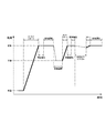
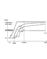
図16は、気温状態からのシステムの立上げ(コールドスタート)における各器の温度変化を示している。コールドスタートにおいては、関係機器の起動操作を経て、システム全体が気温レベルの温度となっている状態から、まず熱風生成装置において補助燃料を燃焼させて熱風を生成し、熱風温度を徐々に上げ、最終的に約1050℃の熱風を予熱器に導いてヒートキャリアを気温レベルの温度から加熱・昇温していく。システムは、停止している間に、気温状態まで冷めた状態にあり、また、雨水の浸入や炉内結露等により炉内が湿っている場合もある。予熱器内のヒートキャリアが十分に加熱された時点、例えば予熱器から出て行く排ガス(予熱器排ガス)がおよそ200℃を超えた時点から、ヒートキャリアの循環も開始され、予熱器の下に設置された改質器に落とされる。同時に、改質器にあった冷えたヒートキャリアもその下に設けられた熱分解器に落とされ、さらに、熱分解器のヒートキャリアも排出が始まって、システム全体のヒートキャリアが循環を始める。このように、予熱器で昇温されたヒートキャリアは、循環に伴って、改質器、熱分解器、分離機、移送装置(バケットコンベア)など、循環経路に熱を供給し、システム全体を昇温していく。昇温過程では、システム内に水分があると、水分が蒸発するまで100℃で暫く温度上昇が停滞することもあるが、蒸発が終わると再び上昇に転じ、熱分解器の温度が定常運転温度(600度程度)に達した時点から原料の供給を開始してその熱分解(吸熱反応)で熱分解器の機器制限温度を超える過剰な温度上昇を抑制しつつ、改質器が定常運転温度(950度程度)に到達するのを待つ。 FIG. 16 shows the temperature change of each unit at the start-up (cold start) of the system from the air temperature state. In the cold start, through the startup operation of the related equipment, from the state where the entire system is at the temperature level temperature, first, the hot air generator burns auxiliary fuel to generate hot air, gradually increasing the hot air temperature, Finally, hot air of about 1050 ° C. is guided to the preheater to heat and heat the heat carrier from the temperature level. While the system is stopped, the system is cooled to a temperature state, and the inside of the furnace may be moistened due to intrusion of rainwater or condensation in the furnace. When the heat carrier in the preheater is sufficiently heated, for example, when the exhaust gas (preheater exhaust gas) coming out of the preheater exceeds approximately 200 ° C., the circulation of the heat carrier is also started under the preheater. It is dropped into the installed reformer. At the same time, the cooled heat carrier in the reformer is also dropped into the thermal decomposer provided thereunder, and further, the heat carrier of the thermal decomposer starts to be discharged, and the heat carrier of the entire system starts to circulate. As described above, the heat carrier heated by the preheater supplies heat to the circulation path such as a reformer, a thermal decomposer, a separator, and a transfer device (bucket conveyor) along with the circulation, The temperature rises. In the temperature raising process, if there is moisture in the system, the temperature rise may stagnate for a while at 100 ° C until the moisture evaporates, but once the evaporation is over, it starts to rise again, and the temperature of the pyrolyzer changes to the steady operating temperature. Starting from the point of time when the temperature reaches (about 600 degrees), the reformer operates at the steady operating temperature while suppressing excessive temperature rise exceeding the temperature limit of the thermal cracker due to its thermal decomposition (endothermic reaction). Wait for it to reach (about 950 degrees).
ヒートキャリアは、予め予熱器、改質器、熱分解器、分離機、バケットコンベアなどに適正な量が詰め込まれており、予め設定された循環量となるように循環される。例えば、予熱器と熱分解器に設けたヒートキャリアのレベル計からの信号により、予熱器と熱分解器のヒートキャリアの堆積レベルが一定の範囲に納まるように一部のセグメントバルブ開閉が管理され、原料投入時に熱分解器で発生するチャーによる熱分解器からの排出量の増大化時の排出量の微調整はこのレベル計信号に基づいて行われる。 An appropriate amount of the heat carrier is packed in advance in a preheater, a reformer, a thermal decomposer, a separator, a bucket conveyor, and the like, and is circulated so as to have a preset circulation amount. For example, the signal from the heat carrier level meter installed in the preheater and pyrolyzer controls the opening and closing of some segment valves so that the accumulation level of the heat carrier in the preheater and pyrolyzer falls within a certain range. The fine adjustment of the discharge amount when the discharge amount from the pyrolyzer is increased by the char generated in the pyrolyzer when the raw material is charged is performed based on this level meter signal.
ヒートキャリア循環型システムの場合、ヒートキャリアの循環量は、改質器と熱分解器の間に設けられたセグメントバルブの開閉頻度(時間間隔)を操作することにより調節が可能である。ヒートキャリアは、システム内を循環しながら、昇温・放熱を繰り返すこととなるが、この1サイクルは、ヒートキャリア総量を時間当たりの循環量で割ることで得られ、通常の場合では、12〜8時間がサイクルタイムとしてある。例えば、ヒートキャリアの全体量が約4.7トンの場合、熱媒体の循環速度は400〜600kg/h程度となる。 In the case of the heat carrier circulation type system, the circulation amount of the heat carrier can be adjusted by operating the opening / closing frequency (time interval) of the segment valve provided between the reformer and the pyrolyzer. The heat carrier is repeatedly heated and radiated while circulating in the system, but this one cycle is obtained by dividing the total amount of heat carrier by the amount of circulation per hour. 8 hours is the cycle time. For example, when the total amount of the heat carrier is about 4.7 tons, the circulation rate of the heat medium is about 400 to 600 kg / h.
しかしながら、このようなヒートキャリア循環型システムは、改質器及び熱分解器をそれぞれ異なる定常運転温度に導くのが容易ではなく、システムを定常運転温度まで高速に昇温できないという問題点を有していた。 However, such a heat carrier circulation type system has a problem that it is not easy to guide the reformer and the pyrolyzer to different steady operation temperatures, and the system cannot be heated up to the steady operation temperature at high speed. It was.
例えば、ヒートキャリアの全体量が約4.7トン、ヒートキャリアの循環速度が400〜600kg/h程度のヒートキャリア循環型システムにおいては、システム温度が気温程度(例えば改質器25℃、熱分解器25℃)まで低下した状態から熱分解ガスの水蒸気改質まで可能な温度、即ち改質器を950℃、熱分解器を有機物の熱分解が可能な550℃の水準まで昇温するためには、機器からの放熱もあって、凡そヒートキャリアを7サイクル以上、日数にして3〜4日、時にはそれ以上循環させる必要がある。
For example, in a heat carrier circulation type system in which the total amount of heat carrier is about 4.7 tons and the heat carrier circulation rate is about 400 to 600 kg / h, the system temperature is about the temperature (for example,
このように、システムを熱分解ガスの水蒸気改質まで可能な温度にするのに要する時間が長いと、稼動日の朝にシステムを起動して、その日の夕方には運転を停止する、というデイリースタート・デイリーストップ(DSSと略される。)は不可能である。昇温時間が長い、という問題点だけであれば、システムを停止せずに24時間連続運転を行うことにより解決できるが、例えばヒートキャリア循環型システムで生成したガスを用いて発電を行い、売電を行う場合は、電気買取価格が低く人件費が高い夜間の収益が極端に低下する場合等、24時間連続運転が適さない場合もある。 In this way, if the time required to bring the system to a temperature capable of steam reforming of the pyrolysis gas is long, the system is started on the morning of the operation day and stopped in the evening of that day. Start daily stop (abbreviated as DSS) is impossible. If there is only a problem that the temperature rise time is long, it can be solved by performing continuous operation for 24 hours without stopping the system. For example, the gas generated by the heat carrier circulation system is used for power generation and sales. When electricity is used, 24-hour continuous operation may not be suitable, for example, when the profit at night is extremely low due to low electricity purchase prices and high labor costs.
また、週末に操業を休む場合、改めて月曜日からシステムの昇温に入るのでは、昇温に時間がかかり過ぎて、その日のガス製造や発電ができなくなってしまう。 In addition, when the operation is closed on the weekend, if the temperature of the system is started again from Monday, it takes too much time to raise the temperature, and gas production and power generation on that day cannot be performed.
さらに、別の問題として、システムの昇温過程、原料の過剰供給により反応器の温度が極端に低下した場合、反応器の温度を規定の温度に戻そうとしても、直ぐに戻すことができず、不経済な運転を強いられることも問題である。 Furthermore, as another problem, when the temperature of the reactor is extremely lowered due to the temperature rising process of the system or excessive supply of raw materials, even if trying to return the temperature of the reactor to the specified temperature, it cannot be returned immediately, It is also a problem to be forced to drive economically.
そこで、本発明の主たる課題は、ヒートキャリア循環型の有機物質のガス化システムにおける高速昇温方法を提供することにある。 Therefore, a main problem of the present invention is to provide a high-speed temperature raising method in a heat carrier circulation type organic substance gasification system.
上記課題を解決した本発明は、次記のとおりである。
<請求項1記載の発明>
熱を運ぶための多数のヒートキャリアと、このヒートキャリアを加熱するための予熱器と、熱分解ガスの水蒸気改質を行うための改質器と、有機物質原料を熱分解するための熱分解器と、熱風を生成する熱風生成装置とを備え、
前記ヒートキャリアを、前記予熱器、改質器、及び熱分解器の順に通した後、移送装置により再び予熱器に戻して循環させるとともに、前記熱分解器内に有機物質原料を供給し、前記改質器内に対して直接又は間接的に水蒸気を供給し、
前記熱分解器内では、前記有機物質原料を、加熱されたヒートキャリアと接触させることによりチャーと熱分解ガスとに熱分解し、熱分解ガスはヒートキャリアに対して向流接触しながら改質器へ供給し、
前記改質器では、前記熱分解ガスを前記ヒートキャリアにより加熱しつつ前記水蒸気と接触させることにより水素含有濃度を向上させたガスを生成し、
前記熱風生成装置では、熱風を生成して予熱器に供給し、
前記予熱器では、前記熱風生成装置から供給される熱風を、前記予熱器内を堆積状態で通過するヒートキャリア間に通して、ヒートキャリアと直接接触することによりヒートキャリアを加熱する、
ように構成した有機物質のガス化システムにおける高速昇温方法であって;
前記熱分解器に対する前記有機物質原料の供給、及び前記ヒートキャリアの循環をそれぞれ停止した状態で、前記熱風生成装置から前記予熱器へ熱風供給する、予熱器昇温運転を行い、
前記予熱器内の温度が所定の予熱器定常運転温度に達した後に、前記有機物質原料の供給停止状態及び前記熱風供給状態を継続しつつ、前記ヒートキャリアの循環を行う急加熱運転を、前記改質器内の温度及び熱分解器内の温度が所定の改質器定常運転温度及び熱分解器定常運転温度にそれぞれ達するまで行う、
ことを特徴とする有機物質のガス化システムにおける高速昇温方法。
The present invention that has solved the above problems is as follows.
<Invention of Claim 1>
A number of heat carriers for carrying heat, a preheater for heating the heat carrier, a reformer for performing steam reforming of the pyrolysis gas, and pyrolysis for pyrolyzing the organic material raw material And a hot air generator for generating hot air,
The heat carrier is passed through the preheater, the reformer, and the thermal decomposer in this order, and then returned to the preheater by the transfer device and circulated, and the organic material raw material is supplied into the thermal decomposer, Supplying steam directly or indirectly into the reformer,
In the pyrolyzer, the organic material is pyrolyzed into char and pyrolysis gas by bringing it into contact with a heated heat carrier, and the pyrolysis gas is reformed in countercurrent contact with the heat carrier. Supply
In the reformer, a gas having an improved hydrogen-containing concentration is produced by bringing the pyrolysis gas into contact with the water vapor while being heated by the heat carrier,
In the hot air generator, hot air is generated and supplied to the preheater,
In the preheater, the hot air supplied from the hot air generator is passed between the heat carriers passing through the preheater in a deposited state, and the heat carrier is heated by directly contacting the heat carrier.
A method of fast heating in an organic material gasification system configured as follows:
In the state where supply of the organic material raw material to the pyrolyzer and circulation of the heat carrier are stopped, hot air is supplied from the hot air generator to the preheater, and a preheater heating operation is performed.
After the temperature in the preheater reaches a predetermined preheater steady operation temperature, the rapid heating operation for circulating the heat carrier while continuing the supply stop state of the organic material and the hot air supply state, Until the temperature in the reformer and the temperature in the pyrolyzer reach the predetermined reformer steady-state operating temperature and the thermal cracker steady-state operating temperature, respectively.
A method for rapidly raising temperature in a gasification system for organic substances.
(作用効果)
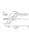
このように、ヒートキャリアの循環及び原料供給を停止した状態で、予熱器内の温度を定常運転温度まで昇温した後、原料供給を開始せずに、ヒートキャリアの循環を開始すると、各器の定常運転温度の大小関係と加熱順番との関係の影響もあり、図15に示すように、熱分解器が機器制限温度を超えることもなく、改質器及び熱分解器の温度が円滑に定常運転温度に導かれる。そして、改質器及び熱分解器が定常運転温度に達してから原料供給を開始しても、ガス化不可能となるような温度低下は防ぐことができる。しかも、この効果は、後述するコールドスタートだけでなく、ホットスタートの場合でも発揮される。よって、本発明によれば、システムをガス化可能な温度まで高速に昇温できるようになる。
これに対して、ヒートキャリアの循環及び原料供給を行いつつシステム全体の昇温を開始すると、ヒートキャリアが熱分解器を経て予熱器に戻る頃には低温になり過ぎ、熱分解器の定常運転温度が最も低いこともあって、図16に実線で、また図15に二点鎖線で示すように、熱分解器は定常運転温度に達していながら改質器は定常運転温度に達せず、ガス化不可能という中途半端な状態が続いてしまう。つまり、これが、ヒートキャリア循環型システムにおける昇温長期化の主要因である。
(Function and effect)
In this way, when the circulation of the heat carrier and the supply of the raw material are stopped, the temperature in the preheater is raised to the steady operation temperature, and then the supply of the heat carrier is started without starting the supply of the raw material. As shown in FIG. 15, the temperature of the reformer and the pyrolyzer is smoothly increased without exceeding the temperature limit of the equipment. Guided to steady operating temperature. And even if the raw material supply is started after the reformer and the pyrolyzer reach the steady operation temperature, it is possible to prevent a temperature drop that makes gasification impossible. Moreover, this effect is exhibited not only in a cold start described later but also in a hot start. Therefore, according to the present invention, the temperature of the system can be increased to a temperature at which gasification is possible.
On the other hand, when the temperature of the entire system is started while circulating the heat carrier and supplying the raw material, the temperature becomes too low when the heat carrier returns to the preheater via the thermal decomposer, and the thermal decomposer is in steady operation. Since the temperature is the lowest, as shown by a solid line in FIG. 16 and a two-dot chain line in FIG. 15, the pyrolyzer reaches the steady operating temperature, but the reformer does not reach the steady operating temperature, and the gas A half-finished situation that cannot be realized continues. That is, this is the main factor of prolonged temperature rise in the heat carrier circulation type system.
<請求項2記載の発明>
前記予熱器定常運転温度は1000℃以上であり、前記改質器定常運転温度は950℃以上であり、前記熱分解器定常運転温度は550℃以上である、請求項1記載の有機物質のガス化システムにおける高速昇温方法。
<Invention of
2. The organic substance gas according to claim 1, wherein the preheater steady operation temperature is 1000 ° C. or more, the reformer steady operation temperature is 950 ° C. or more, and the pyrolyzer steady operation temperature is 550 ° C. or more. Method for rapid temperature increase in a computer system.
(作用効果)
各器の定常運転温度は上記範囲とするのが好ましい。
(Function and effect)
The steady operating temperature of each unit is preferably within the above range.
<請求項3記載の発明>
予熱器、改質器及び熱分解器を気温状態からそれぞれ予熱器定常運転温度、改質器定常運転温度及び熱分解器定常運転温度まで昇温する、コールドスタートに際し、
前記有機物質原料の供給及び前記ヒートキャリアの循環を行わずに、前記予熱器に対して熱風の供給を開始し、前記予熱器内温度が所定温度を超えた後に前記熱風供給を継続したまま前記ヒートキャリアの循環を開始し、
このヒートキャリアの循環により前記熱分解器内温度が熱分解器定常運転温度に到達した後に、前記予熱器昇温運転を開始し、
この予熱器昇温運転により、前記予熱器内の温度が所定の予熱器定常運転温度に達した後に、前記改質器内の温度及び熱分解器内の温度が所定の改質器定常運転温度及び熱分解器定常運転温度にそれぞれ達するまで前記急加熱運転を行い、しかる後に前記有機物質原料の供給を開始する、請求項1又は2記載の有機物質のガス化システムにおける高速昇温方法。
<Invention of Claim 3>
At the time of cold start, the preheater, the reformer, and the thermal cracker are heated from the air temperature state to the preheater steady operation temperature, the reformer steady operation temperature, and the thermal cracker steady operation temperature, respectively.
Without supplying the organic material raw material and circulating the heat carrier, start supplying hot air to the preheater, and the hot air supply continues after the preheater temperature exceeds a predetermined temperature. Started circulating the heat carrier,
After the temperature inside the pyrolyzer reaches the pyrolyzer steady operation temperature due to the circulation of the heat carrier, the preheater heating operation is started,
After the preheater temperature increasing operation, the temperature in the preheater reaches the predetermined preheater steady operation temperature, and then the temperature in the reformer and the temperature in the pyrolyzer are the predetermined reformer steady operation temperature. 3. The high-speed heating method in the organic material gasification system according to claim 1, wherein the rapid heating operation is performed until reaching a steady operation temperature of the pyrolyzer, and then the supply of the organic material raw material is started.
(作用効果)
前述したとおり、従来のコールドスタートでは、水蒸気改質の出来る状態、すなわち改質器内温度が950℃に到達するには3〜4日間、低気温、強風下などの悪条件下ではそれ以上の継続運転を必要とする。これに対して、本発明のコールドスタートでは、熱分解器が定常運転温度に達するまでは従来同様に昇温を行うが、その後に予熱器昇温運転及び急加熱運転を介在させることにより加熱効率が改善され、各器の温度が円滑且つ高速に定常運転温度に到達するようになる。
(Function and effect)
As described above, in the conventional cold start, the state in which steam reforming can be performed, that is, the temperature inside the reformer reaches 950 ° C. for 3 to 4 days. Requires continuous operation. On the other hand, in the cold start of the present invention, the temperature is raised as before until the pyrolyzer reaches the steady operation temperature, but after that, the heating efficiency is increased by interposing the preheater temperature raising operation and the rapid heating operation. As a result, the temperature of each vessel reaches the steady operating temperature smoothly and rapidly.
<請求項4記載の発明>
前記予熱器内の温度、前記改質器内の温度、及び前記熱分解器内の温度が、前記予熱器定常運転温度、前記改質器定常運転温度、及び前記熱分解器定常運転温度にそれぞれ達している状態で、前記予熱器に対する熱風の供給、前記ヒートキャリアの循環、及び前記有機物質原料の供給を行う定常運転から、
前記有機物質原料の供給を停止した状態で、前記予熱器に対する供給熱量の増減及び前記ヒートキャリアの循環速度の増減の少なくとも一方を行い、予熱器に対する熱風供給量及び供給熱風温度のうち少なくとも一方を低減し、且つ前記予熱器内の温度を前記予熱器定常運転温度よりも低く且つ所定の下限温度以上、前記熱分解器内の温度を前記熱分解器定常運転温度よりも低く且つ所定の下限温度以上、及び前記改質器内の温度を前記改質器定常運転温度よりも低く且つ所定の下限温度以上にそれぞれ保持する、保温運転に移行した後、
この保温運転から前記予熱器昇温運転に移行し、前記予熱器内の温度が所定の予熱器定常運転温度に達した後に、前記改質器内の温度及び熱分解器内の温度が所定の改質器定常運転温度及び熱分解器定常運転温度にそれぞれ達するまで前記急加熱運転を行い、しかる後に前記有機物質原料の供給を再開する、ホットスタートを行う、請求項1又は2記載の有機物質のガス化システムにおける高速昇温方法。
<Invention of
The temperature in the preheater, the temperature in the reformer, and the temperature in the thermal decomposer are the preheater steady operation temperature, the reformer steady operation temperature, and the thermal cracker steady operation temperature, respectively. From the steady operation of supplying hot air to the preheater, circulating the heat carrier, and supplying the organic material raw material,
In a state where the supply of the organic material raw material is stopped, at least one of increase / decrease in the amount of heat supplied to the preheater and increase / decrease in the circulation rate of the heat carrier is performed, and at least one of the hot air supply amount and the supply hot air temperature to the preheater is performed. The temperature in the preheater is lower than the steady operation temperature of the preheater and equal to or higher than a predetermined lower limit temperature, and the temperature in the thermal decomposer is lower than the steady operation temperature of the thermal decomposer and a predetermined lower limit temperature. After shifting to the heat retention operation, the temperature inside the reformer is lower than the reformer steady operation temperature and at or above a predetermined lower limit temperature,
After the temperature maintaining operation is shifted to the preheater temperature increasing operation and the temperature in the preheater reaches a predetermined preheater steady operation temperature, the temperature in the reformer and the temperature in the thermal decomposer are set to a predetermined value. The organic substance according to claim 1, wherein the rapid heating operation is performed until the steady state temperature of the reformer and the steady state temperature of the pyrolyzer are respectively reached, and then the supply of the organic material raw material is resumed, and a hot start is performed. Fast heating method in the gasification system.
(作用効果)
前述したとおり、ガス化システムを運用していく上では一時的に操業を停止する方が望ましい場合もある。例としては、生成ガスを用いて発電を行い、売電を行うにあたり、電気買取価格が低く人件費が高い夜間の収益が極端に低下する場合や、週末、連休に操業を休む場合である。このような一時的な操業停止において、システムをある程度まで冷却してしまうと、システムを再びガス化可能な状態まで昇温するのには長時間を要する。
例えば、本システムが、連休前に原料供給を停止し、数日後の連休明けから原料供給を開始する場合、一旦熱風送風まで停止するシステム全停止の状態にすると、熱分解器の内部温度は気温が2℃から4℃の冬季の計測では24時間で500℃から100℃に冷却する。予熱器など最も熱が残る部分でも、5日から6日でほぼ気温程度まで冷却する。一旦システムが気温程度まで冷却してしまうと、コールドスタートの昇温となるため、その昇温には長時間を要し、連休明けから昇温に入っても直ぐにはガス化を開始することはできないこととなる。
そこで、システムを一時的に停止する場合、上述のように保温運転を行うことによりシステムを一定温度以上に保ち、その後に本発明の予熱器昇温運転及び急加熱運転を経て原料供給を再開するというホットスタートを採用することにより、エネルギー消費を抑えつつシステムの再開を速やかに行うことができるようになる。
なお、上述の保温運転と次述の待機運転との相違点は、主に保とうとするシステム温度の違いであり、保温運転は、効率的なホットスタート昇温を行うために必要な下限温度に維持する運転であり、待機運転は、何時でも原料供給できる定常運転温度状態、すなわち高温に保つ運転である。待機運転及び保温運転は、共に原料供給を停止した状態でシステムの温度を保つものであり、高温に保つほどエネルギー消費が大きくなるため、数日間の休業の際には、次述の待機運転ではなく、上述の保温運転を採用する方が合理的である。
(Function and effect)
As described above, it may be desirable to temporarily stop the operation in order to operate the gasification system. For example, when generating electricity using the generated gas and selling power, there are cases where nighttime profits with low electricity purchase prices and high labor costs are drastically reduced, or operations are closed on weekends and consecutive holidays. In such a temporary shutdown, if the system is cooled to some extent, it takes a long time to raise the temperature of the system to a state where it can be gasified again.
For example, if this system stops the supply of raw materials before consecutive holidays and starts the supply of raw materials after the consecutive holidays several days later, once the system is stopped until hot air blowing is stopped, the internal temperature of the pyrolyzer However, in winter measurements from 2 ° C to 4 ° C, it cools from 500 ° C to 100 ° C in 24 hours. Even in the part where the heat remains most, such as a preheater, it is cooled to about the temperature in 5 to 6 days. Once the system has cooled down to about the temperature, it will be cold-started, so it takes a long time to start, and gasification will not begin immediately even after the temperature rises from the end of consecutive holidays. It will not be possible.
Therefore, when the system is temporarily stopped, the heat insulation operation is performed as described above to keep the system at a certain temperature or higher, and then the raw material supply is resumed through the preheater heating operation and the rapid heating operation of the present invention. By adopting such a hot start, the system can be restarted quickly while suppressing energy consumption.
The difference between the above-mentioned heat insulation operation and the standby operation described below is mainly the difference in the system temperature to be maintained. The heat insulation operation is performed at the lower limit temperature required for efficient hot start temperature increase. The standby operation is a steady operation temperature state in which raw materials can be supplied at any time, that is, an operation that maintains a high temperature. In both standby operation and heat insulation operation, the temperature of the system is maintained in a state where the material supply is stopped, and the energy consumption increases as the temperature is kept high. Instead, it is more reasonable to employ the above-described heat retention operation.
<請求項5記載の発明>
前記予熱器内の温度、前記改質器内の温度、及び前記熱分解器内の温度が、前記予熱器定常運転温度、前記改質器定常運転温度、及び前記熱分解器定常運転温度にそれぞれ達しており、且つ前記原料供給を停止している状態から、前記原料供給を開始するまでの間、
(い)前記ヒートキャリアの循環の一時的又は連続的な停止、
(ろ)前記ヒートキャリアの循環の一時的又は連続的な実行、並びに
(は)前記予熱器に対する熱風供給量及び供給熱風温度のうち少なくとも一方の増減、
の少なくとも一つの操作により、前記予熱器内の温度、前記改質器内の温度、及び前記熱分解器内の温度を、前記予熱器定常運転温度、前記改質器定常運転温度、及び前記熱分解器定常運転温度にそれぞれ維持する、待機運転を行う、請求項1〜4のいずれか1項に記載のガス化システムにおける高速昇温方法。
<Invention of Claim 5>
The temperature in the preheater, the temperature in the reformer, and the temperature in the thermal decomposer are the preheater steady operation temperature, the reformer steady operation temperature, and the thermal cracker steady operation temperature, respectively. From the state where the raw material supply is stopped until the raw material supply is started,
(Ii) Temporary or continuous stop of circulation of the heat carrier,
(B) Temporary or continuous execution of circulation of the heat carrier, and (ha) increase or decrease of at least one of hot air supply amount and supply hot air temperature to the preheater,
The temperature in the preheater, the temperature in the reformer, and the temperature in the pyrolyzer are changed to the preheater steady operation temperature, the reformer steady operation temperature, and the heat by the at least one operation of The high-speed temperature rising method in the gasification system of any one of Claims 1-4 which performs standby operation | maintenance each maintained to a cracker steady operation temperature.
(作用効果)
例えば、本ガス化システムを運用していく上では、原料供給を行わない状態でシステム温度を定常運転温度に保つことが望ましい場合がある。例えば、急加熱運転によりシステムの各機器は定常運転温度に達したが、原料供給開始までにしばし原料供給を始められない時間がある場合、或いはDSSにおける夜間の原料供給停止時に、翌日の原料供給再開に向けシステム温度を定常運転温度状態に保つ場合がそれである。このような場合、上述の待機運転を行うことにより、何時でも原料供給可能な温度状態を保つことができる。より詳細には、(い)の操作によって各機器の温度を放熱により下げることができ、(ろ)の操作によって各機器の温度を熱供給により上げることができ、(は)の操作によってヒートキャリアの加熱の程度を変化させることができる。
(Function and effect)
For example, in operating this gasification system, it may be desirable to keep the system temperature at a steady operating temperature without supplying raw materials. For example, when the equipment of the system has reached a steady operating temperature due to rapid heating operation, but there is a time when the raw material supply cannot be started for a while until the raw material supply starts, or when the nighttime raw material supply stop in DSS, This is the case when the system temperature is kept at the steady operating temperature state for resumption. In such a case, by performing the standby operation described above, it is possible to maintain a temperature state at which the raw material can be supplied at any time. More specifically, the temperature of each device can be lowered by heat radiation by the operation of (ii), the temperature of each device can be raised by the heat supply by the operation of (ro), and the heat carrier by the operation of (ha). The degree of heating can be changed.
<請求項6記載の発明>
前記予熱器内の温度、前記改質器内の温度、及び前記熱分解器内の温度が、前記予熱器定常運転温度、前記改質器定常運転温度、及び前記熱分解器定常運転温度にそれぞれ達している状態で、前記熱風の供給、前記ヒートキャリアの循環、及び前記有機物質原料の供給を行う定常運転中に、前記熱分解器内温度が前記熱分解器定常運転温度未満となったとき、
前記予熱器昇温運転を行い、前記予熱器内の温度が所定の予熱器定常運転温度に達した後に、前記改質器内の温度及び熱分解器内の温度が所定の改質器定常運転温度及び熱分解器定常運転温度にそれぞれ達するまで前記急加熱運転を行う、リセット操作を実行し、このリセット操作後に、リセット操作前よりも少ない供給量で前記有機物質原料の供給を再開する、
請求項1〜5のいずれか1項に記載の有機物質のガス化システムにおける高速昇温方法。
<Invention of
The temperature in the preheater, the temperature in the reformer, and the temperature in the thermal decomposer are the preheater steady operation temperature, the reformer steady operation temperature, and the thermal cracker steady operation temperature, respectively. When the temperature inside the pyrolyzer becomes less than the steady operation temperature of the pyrolyzer during steady operation in which the hot air is supplied, the heat carrier is circulated, and the organic material raw material is supplied. ,
After the preheater temperature increasing operation is performed and the temperature in the preheater reaches a predetermined preheater steady operation temperature, the temperature in the reformer and the temperature in the pyrolyzer are in a predetermined reformer steady operation. The rapid heating operation is performed until the temperature and the pyrolyzer steady operation temperature are reached, respectively, a reset operation is performed, and after the reset operation, the supply of the organic material raw material is resumed with a smaller supply amount than before the reset operation.
The high-speed temperature rising method in the gasification system of the organic substance of any one of Claims 1-5.
(作用効果)
本システムは、ヒートキャリアをシステム内で循環させ、予熱器での蓄熱と改質器と熱分解器での放熱を利用して、熱分解器の中での有機物質の熱分解と改質器の中での水蒸気改質を行うシステムであるが、熱分解器に原料が供給され過ぎると、吸熱反応と水分の蒸発等により、熱分解器内でヒートキャリアの温度低下が起こり、この温度低下が許容範囲を超えると、ヒートキャリア温度が循環の度に下がる温度低下スパイラルに入る。例えば、通常の場合、熱分解器内のヒートキャリア温度として許容できる下限温度はおよそ500℃であり、この温度を下回ると、予熱器に戻る時には400℃以下となり、予熱器での昇温の限界もあって、温度低下スパイラルという悪循環に陥り、ヒートキャリアを定常運転温度に戻せなくなる。これに対して、上述のリセット操作を行うと、温度低下の悪循環から抜け出すことができる。
(Function and effect)
This system circulates the heat carrier in the system and utilizes the heat storage in the preheater and the heat release in the reformer and pyrolyzer to thermally decompose the organic substance in the pyrolyzer and the reformer. However, if the raw material is supplied too much to the pyrolyzer, the temperature of the heat carrier will decrease in the pyrolyzer due to endothermic reaction and evaporation of moisture. When the temperature exceeds the allowable range, the heat carrier temperature enters a temperature lowering spiral that decreases with each circulation. For example, in the normal case, the lower limit temperature allowable as the heat carrier temperature in the pyrolyzer is approximately 500 ° C., and below this temperature, when returning to the preheater, the temperature becomes 400 ° C. or lower, and the temperature rise limit in the preheater For this reason, a vicious circle called a temperature lowering spiral occurs, and the heat carrier cannot be returned to the steady operating temperature. On the other hand, when the above-described reset operation is performed, it is possible to escape from a vicious cycle of temperature decrease.
<請求項7記載の発明>
前記予熱器内温度が前記予熱器定常運転温度に達し、前記予熱器の排ガス温度が機器制限温度を超えたとき、次の、
(イ)前記ヒートキャリアの循環が停止しているとき、一時的に、前記ヒートキャリアの循環を開始する、
(ロ)一時的又は連続的に、前記予熱器に対する熱風供給量及び供給熱風温度のうち、供給熱風温度は維持したまま熱風供給量を減少させる、
(ハ)一時的に、前記予熱器への熱風供給を停止する、
(ニ)一時的に、予熱器に対して冷却用空気を送風する、
の少なくとも一つの過熱抑制操作を実行する、
請求項1〜6のいずれか1項に記載の有機物質のガス化システムにおける高速昇温方法。
<Invention of Claim 7>
When the preheater internal temperature reaches the preheater steady operation temperature and the exhaust gas temperature of the preheater exceeds the equipment limit temperature, the following:
(I) When the circulation of the heat carrier is stopped, the circulation of the heat carrier is temporarily started.
(B) Temporarily or continuously, among the hot air supply amount and supply hot air temperature to the preheater, the supply hot air temperature is maintained and the hot air supply amount is decreased.
(C) Temporarily stopping the supply of hot air to the preheater,
(D) Temporarily blow cooling air to the preheater,
Performing at least one overheat suppression operation of
The high-speed temperature rising method in the gasification system of the organic substance of any one of Claims 1-6.
(作用効果)
予熱器昇温運転中、急加熱運転中、又は待機運転中等に、予熱器内温度が予熱器定常運転温度に達し、さらに温度が上昇して予熱器の排ガス温度が機器制限温度を超えるおそれがあるが、そのときは、上記(イ)〜(ニ)の少なくとも一つの過熱抑制操作を実行することにより、予熱器の温度低下を抑えつつ、運転継続による予熱器の過熱を防止できるようになる。なお、一時的とは断続的を含む意味である(以下同じ)。例えば、一時的又は連続的に(イ)のヒートキャリアの循環を再開し、それでも予熱器内温度が下がらないときには、予熱器に対する供給熱風温度は維持したまま熱風供給量を減少させる(ロ)〜(ハ)の操作を行うことによって、予熱器昇温運転等の継続による予熱器の過熱を防止できるのであるが、それでもなお、予熱器の昇温を抑えられない場合もありうる。よって、そのような場合には、上述の(二)のような予熱器冷却行程を行うのが好ましい。
(Function and effect)
During preheater heating operation, rapid heating operation, standby operation, etc., the temperature in the preheater may reach the preheater steady operation temperature, and the temperature may rise and the exhaust gas temperature of the preheater may exceed the equipment limit temperature. However, at that time, it is possible to prevent overheating of the preheater due to continued operation while suppressing the temperature drop of the preheater by executing at least one overheat suppression operation of (i) to (d) above. . The term “temporary” includes intermittent (hereinafter the same). For example, when the circulation of the heat carrier (a) is resumed temporarily or continuously, and the temperature inside the preheater still does not decrease, the supply of hot air to the preheater is maintained and the hot air supply amount is decreased (b) to By performing the operation (c), it is possible to prevent overheating of the preheater due to continuation of the preheater heating operation or the like, but there is still a case where the temperature rise of the preheater cannot be suppressed. Therefore, in such a case, it is preferable to perform the preheater cooling process as described in (2) above.
<請求項8記載の発明>
前記急加熱運転における前記ヒートキャリアの循環開始と同時又はその直前もしくは直後に、前記予熱器に対する熱風供給量及び供給熱風温度の少なくとも一方を増加する、請求項1〜7のいずれか1項に記載の有機物質のガス化システムにおける高速昇温方法。
<Invention of
8. The method according to claim 1, wherein at least one of a hot air supply amount and a supply hot air temperature to the preheater is increased simultaneously with, immediately before or immediately after the start of circulation of the heat carrier in the rapid heating operation. Fast heating method in organic material gasification system.
(作用効果)
急加熱運転においてヒートキャリアの循環を開始すると、予熱器の温度が低下し過ぎるおそれがあるため、このように、ヒートキャリアの循環開始と同時又はその直前もしくは直後に、予熱器に対する熱風供給量及び供給熱風温度の少なくとも一方を増加し、予熱器の温度低下を防止するのが好ましい。
(Function and effect)
When the heat carrier circulation is started in the rapid heating operation, the temperature of the preheater may be excessively lowered. Thus, at the same time as the heat carrier circulation start or immediately before or after the heat carrier supply amount and It is preferable to increase at least one of the supply hot air temperatures to prevent a temperature drop of the preheater.
<請求項9記載の発明>
システムを停止するにあたり、前記熱分解器に対する前記有機物質原料の供給を停止した状態で、前記ヒートキャリアの循環及び前記予熱器への熱風供給を継続する、後処理運転を所定時間を行い、しかる後に、前記ヒートキャリアの循環及び前記予熱器への熱風供給をそれぞれ停止する、請求項1〜8のいずれか1項に記載の有機物質のガス化システムにおける高速昇温方法。
<Invention of
In stopping the system, in a state where the supply of the organic material raw material to the pyrolyzer is stopped, the heat carrier circulation and the hot air supply to the preheater are continued, and a post-processing operation is performed for a predetermined time. The high-speed temperature raising method in the organic material gasification system according to claim 1, wherein the circulation of the heat carrier and the supply of hot air to the preheater are stopped later.
(作用効果)
システムを停止する際、直ちにヒートキャリアの循環をも停止してしまうと、熱分解器に滴下するタールの固化により多数のヒートキャリアが塊状に固まり、次のシステム開始の際にヒートキャリアの循環阻害をもたらすことがある。これに対して、上述のように後処理運転を行うと、熱分解器においてタールが滴下しても熱風により加熱されたヒートキャリアが循環しているため、塊状に固化するといった事態は発生し難くなる。
(Function and effect)
If the heat carrier circulation is stopped immediately when the system is shut down, a large number of heat carriers are agglomerated due to the solidification of the tar dripping into the pyrolyzer, and the heat carrier circulation is inhibited at the start of the next system. May bring. On the other hand, when the post-processing operation is performed as described above, the heat carrier heated by the hot air circulates even when tar is dropped in the pyrolyzer, so that it is difficult to cause a solidified state. Become.
以上のとおり、本発明によれば、ヒートキャリア循環型の有機物質のガス化システムにおいて、システムをガス化可能な温度まで高速に昇温できるようになる、等の利点がもたらされる。 As described above, according to the present invention, in the heat carrier circulation type organic substance gasification system, it is possible to increase the temperature of the system to a temperature at which gasification is possible at high speed.
以下、本発明の一実施形態について添付図面を参照しながら詳説する。
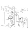
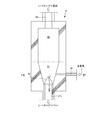
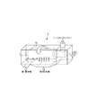
本発明に係るガス化システムは、例えば図1に示される機器構成で実施することができる。すなわち、図1に示されるガス化システムは、上から順に、予熱器2、改質器3、熱分解器4、及び分離機5を直列に備えており、熱を運ぶための多数のヒートキャリア(熱担持媒体)が、予熱器2で加熱されてから改質器3、熱分解器4及び分離機5の順に通された後、バケットコンベア等の移送装置6により再び予熱器2に戻されるように構成されているものである。
Hereinafter, an embodiment of the present invention will be described in detail with reference to the accompanying drawings.
The gasification system according to the present invention can be implemented, for example, with the equipment configuration shown in FIG. That is, the gasification system shown in FIG. 1 includes, in order from the top, a
ヒートキャリアとしては、粒径5〜20mm程度、好ましくは粒径8〜12mm程度の粒状物を用いることができ、特に球状のものが好適である。また、ヒートキャリアの素材としては、アルミナ等のように硬質で熱容量の大きなものが好適である。なお、粒径とは、JIS Z 8801−1「試験用ふるい−第 1 部:金属製網ふるい」に規定されるふるいを用い、JIS A 1102 「骨材のふるい分け試験方法」に準じて測定される、ふるい分け法による粒径(ふるいの目開き)を意味する(以下同じ)。 As the heat carrier, a granular material having a particle size of about 5 to 20 mm, preferably about 8 to 12 mm can be used, and a spherical one is particularly suitable. Moreover, as a heat carrier material, a hard material having a large heat capacity such as alumina is suitable. The particle size is measured according to JIS A 1102, “Aggregate Screening Test Method”, using a sieve specified in JIS Z 8801-1, “Sieving for Testing-Part 1: Metal Mesh Screen”. This means the particle size (screen opening) by the sieving method (the same applies hereinafter).
有機物質原料は原料ホッパ17に貯留されており、スクリューコンベア14やロータリーフィーダ等の適宜の定量供給装置により切り出され、例えば改質器3と熱分解器4とを繋ぐ供給管路3xを介して、熱分解器4の上部供給口へ連続的に定量供給される。この供給管路3xにはバルブ3bが設けられており、ヒートキャリア等の固形分の通過を停止させる等の制御が可能になっている。ヒートキャリアの循環中は、このバルブ3bが所定の間隔で開閉を繰り返し、ヒートキャリア等の固形分が断続的に定量通過するようになっている。
The organic material raw material is stored in the
有機物質原料としては、間伐材や剪定枝等の木質バイオマスが好適であるが、プラスチック等他の廃棄物等を用いることもできる。廃ラスチックの例としては、塩化ビニル、ポリウレタン、メタクリル樹脂、ポリスチレン、ポリプロピレン、ポリエチレン等を挙げることができる。有機物質原料の形状は特に限定されないが、φ1〜50mm程度、L=1〜150mm程度、特にヒートキャリアの粒径の1.6倍以下程度の粒径に破砕、切削、ペレット化したものを好適に用いることができる。 As the organic material raw material, woody biomass such as thinned wood and pruned branches is suitable, but other wastes such as plastic can also be used. Examples of the waste plastic include vinyl chloride, polyurethane, methacrylic resin, polystyrene, polypropylene, and polyethylene. The shape of the organic material raw material is not particularly limited, but it is preferably a material that is crushed, cut, and pelletized to a particle diameter of about φ1 to 50 mm, L = 1 to 150 mm, particularly about 1.6 times the particle diameter of the heat carrier. Can be used.
熱分解器4内に供給された有機物質は、予熱器2から改質器3を経て供給された、加熱されたヒートキャリアと混合状態で接触することにより、吸熱反応を起こし、チャー(固体の炭素含有残留物)と熱分解ガス(揮発性相)とに分離される。熱分解器4内の温度は適宜定めることができるが、500〜600℃程度にするのが好ましい。熱分解生成物のうち、固形分であるチャーは、ヒートキャリアとともに供給管路4xを介して分離機5へ供給され、気体である熱分解ガスはヒートキャリアに対して向流接触しながら改質器3へ上昇供給される。この供給管路4xにはバルブ4bが設けられるとともに、その下流側にダンパ4dが二段に設けられており、前者によりヒートキャリア等の固形分の通過を停止させる等の制御が可能になっており、後者により気体分の通過を停止させる等の制御が可能になっている。ヒートキャリアの循環中は、このバルブ4bが所定の間隔で開閉を繰り返すとともに、上下のダンパ4dが開閉動作を反対に行うことにより、気体の通過を遮断しつつ、ヒートキャリア等の固形分が断続的に定量通過するようになっている。
The organic substance supplied into the
改質器3に対しては反応媒体としての水蒸気が供給されており、熱分解ガスがヒートキャリアにより加熱されつつ水蒸気と混合接触することにより、次式の改質反応が起こり、水素含有濃度の高いガスが発生する。改質器3内の温度は適宜定めることができるが、改質を十分かつ確実に行うために950℃以上とするのが好ましい。
CnHm + nH2O → nCO + (m/2+n)H2 …(1)
CO + H2O → H2 + CO2 …(2)
The reformer 3 is supplied with water vapor as a reaction medium. When the pyrolysis gas is heated by the heat carrier and mixed with the water vapor, the reforming reaction of the following formula occurs, High gas is generated. The temperature in the reformer 3 can be determined as appropriate, but is preferably 950 ° C. or higher in order to perform reforming sufficiently and reliably.
C n H m + nH 2 O → nCO + (m / 2 + n) H 2 (1)
CO + H 2 O → H 2 + CO 2 (2)
水蒸気は適宜の方法で供給することができるが、図示例では、貯水タンク19の水を給水ポンプ19pにより汲みだし、廃熱ボイラ(間接接触式熱交換器)7において、改質器3から別途供給される生成ガスの熱を利用して蒸気とした後、改質器3の下部から供給するようにしている。また、改質器3への水蒸気供給とともに又はこれに代えて、改質器3における改質反応に利用する水蒸気を図示するように熱分解器4を介して間接的に供給することもできる。
Although steam can be supplied by an appropriate method, in the illustrated example, the water in the
一方、分離機5では、熱分解器4から供給される混合物がチャーとヒートキャリアとに分離される。分離されたチャーはスクリューコンベア等の移送装置1iにより熱風炉等の熱風生成装置1に供給され、ヒートキャリアは移送装置6により予熱器2に戻される。移送装置6から予熱器2への供給管路6xにはバルブ6bが設けられるとともに、その下流側にダンパ6dが二段に設けられており、前者によりヒートキャリア等の固形分の通過を停止させる等の制御が可能になっており、後者により気体分の通過を停止させる等の制御が可能になっている。ヒートキャリアの循環中は、このバルブ6bが所定の間隔で開閉を繰り返すとともに、上下のダンパ6dが開閉動作を反対に行うことにより、気体の通過を遮断しつつ、ヒートキャリア等の固形分が断続的に定量通過するようになっている。
On the other hand, in the separator 5, the mixture supplied from the
熱風生成装置1はバーナーを備えており、このバーナーを介して炉内に空気が供給されることによりチャーが燃焼し、熱風(高温排ガス)が生成される。熱風生成装置の運転においては、LPG等の気体補助燃料やBDF等の液体燃料を、連続的に又は運転開始時等の必要時にバーナーに供給し、燃焼させることができる。熱風生成装置1で生成された熱風は予熱器2に供給される。また、熱風生成装置1でチャーの燃焼により生成される灰は、熱風生成装置1内で回収され、灰貯留部1pに排出される。
The hot air generating apparatus 1 includes a burner, and the char is burned by supplying air into the furnace through the burner, and hot air (high temperature exhaust gas) is generated. In the operation of the hot air generator, gas auxiliary fuel such as LPG and liquid fuel such as BDF can be supplied to the burner continuously or when necessary, such as at the start of operation, and burned. Hot air generated by the hot air generator 1 is supplied to the
予熱器2では、熱風生成装置1から供給される熱風が、予熱器2内を堆積状態で通過するヒートキャリア間に通され、ヒートキャリアと直接接触することによりヒートキャリアが加熱される。予熱器2で加熱されたヒートキャリアは、供給管路2xを介して改質器3に供給される。この供給管路2xにはバルブ2bが設けられるとともに、その下流側にダンパ2dが二段に設けられており、前者によりヒートキャリア等の固形分の通過を停止させる等の制御が可能になっており、後者により気体分の通過を停止させる等の制御が可能になっている。ヒートキャリアの循環中は、このバルブ2bが所定の間隔で開閉を繰り返すとともに、上下のダンパ2dが開閉動作を反対に行うことにより、気体の通過を遮断しつつ、ヒートキャリア等の固形分が断続的に定量通過するようになっている。
In the
予熱器2でヒートキャリアの加熱利用された熱風は、誘引送風機15により予熱器2から排気され、サイクロン等の分離手段8を介して排気に混入する灰・ダスト(灰以外の粉粒体)Dを取り除かれた後、好適には空気加熱器((間接接触式熱交換器))9において熱風生成装置1へ供給する空気の加熱に利用した後、大気に放出される。なお、空気加熱器9における予熱に先立って、予熱器(間接接触式の熱交換器)9iを利用して水蒸気(前述の方法により製造し、供給できる)と熱交換し、予熱しておくとより好ましい。
The hot air used for heating the heat carrier in the
改質器3で生成された水素高含有の生成ガスは、図示例では、誘引送風機11により改質器3からガス処理・利用設備に送出され、廃熱ボイラ7で250℃程度まで冷却され、続いて湿式スクラバー10に供給されてタールが除去されるとともに40℃程度まで冷却された後、ガスホルダ12に貯留されるようになっている。なお、図示例の湿式スクラバー10は、上部から散水した洗浄水を下部から排出し、冷却器(間接接触式の熱交換器)10cで冷却した後、再度上部から散水するものであり、符号10pは洗浄水循環ポンプを示しており、符号10dは冷却器に対する冷却水の循環を行う冷却水循環ポンプを示しており、符号10tは冷却水を外気により冷却する冷却塔を示しており、符号18は洗浄水を排水処理する排水処理装置を示している。
In the illustrated example, the hydrogen-containing product gas generated by the reformer 3 is sent from the reformer 3 to the gas treatment / use facility by the
生成されるガスの利用形態は特に限定されるものではないが、図示するように、ガスエンジン発電機13を用いて電力に変換するのも一つの好ましい形態である。また、生成ガスの一部を、熱風生成装置1の補助燃料として使用するのも好ましい形態である。
Although the form of use of the generated gas is not particularly limited, as shown in the figure, it is also one preferable form that the
他方、ヒートキャリアの循環サイクルは、各器間に設けられたセグメントバルブ2b,3b,4b,6bの開閉頻度(間隔)のうち、セグメントバルブ3bの開閉頻度を操作することにより調節が可能であり、通常の場合、12〜8時間がサイクルタイムとして適切である。この1サイクルは、ヒートキャリア総量を時間当たりの循環量で割ることで求めることができる。その他のセグメントバルブ2b,4b,6bは、予熱器2と熱分解器4に設置されたヒートキャリアのレベル計によりヒートキャリアの堆積高が測定され、レベルが高い場合には開閉頻度を早め、レベルが低い場合は遅くする自動調整がなされ、予熱器2と熱分解器4のヒートキャリアの堆積高さが一定の範囲に保たれる。
On the other hand, the heat carrier circulation cycle can be adjusted by manipulating the opening / closing frequency of the
(予熱器)
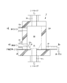
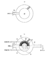
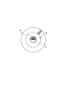
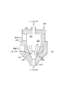
予熱器2は特に限定されないが、例えば図2及び図3に示されるような灰除去手段を有するものが好適である。すなわち、図2及び図3に示される予熱器2は、上下方向に沿う円筒状の上側ヒートキャリア通路20と、この上側ヒートキャリア通路20の下方に連続する漏斗状(逆さ裁頭円錐台状。下側に向かうにつれて径が小さくなる形状であればよい。)の下側ヒートキャリア通路21とを有し、上側ヒートキャリア通路20上面の中央部に供給口20i、下側ヒートキャリア通路21下端に排出口21x、上側ヒートキャリア通路20の側面に排気口20x及び下側ヒートキャリア通路21の側面に熱風吹き出し口22nをそれぞれ有しているものである。
(Preheater)
Although the
図示例では、下側ヒートキャリア通路21は、パンチングメタル等のように多数の透過孔22nが全面に形成された漏斗状部材22により形成されており、この漏斗状部材22の外側を取り囲むように環状スペース23が形成され、この環状スペース23の側面に外部からの熱風供給口24が連通されており、漏斗状部材22の透過孔22nが熱風吹き出し口となり、環状スペース23が熱風吹き出し口22nの全てに連通する分配供給路となる。漏斗状部材22はニッケル合金等の耐熱金属又はアルミナセラミックス等の耐熱セラミックスにより、また、上側ヒートキャリア通路20及び環状スペース23の周壁はアルミナセラミックス等の耐熱セラミクス材により形成することができ、予熱器2の外面は鉄皮により形成することができる。
In the illustrated example, the lower
予熱器2では、上側及び下側ヒートキャリア通路20,21において、ヒートキャリアがある程度の堆積状態を維持しながら下降し、下側ヒートキャリア通路21を通過する過程で各熱風吹き出し口22nから、つまり周方向の複数個所から吹き出される熱風と接触して加熱される。このように、下側ヒートキャリア通路21を通るヒートキャリア群に対して、周方向の複数個所から熱風が供給されると、ヒートキャリアの通過数が下側ヒートキャリア通路21の径の減少に伴って減少することも相まって、熱風生成装置1からの新鮮な熱風がより多くのヒートキャリアに対して直接又はそれに近い状態で接触されるため、ヒートキャリアの加熱効率に優れるようになる。
In the
そして特徴的には、漏斗状部材22の透過孔22nの寸法は、灰・ダストDは通過するがヒートキャリアは通過しないように設定されるとともに、分配供給路である環状スペース23から外部に連通する灰・ダストの抜出口25が形成されている。漏斗状部材22の透過孔22nの形状は、図示例のような円状の他、楕円状、三角形状等、適宜の形状とすることができる。透過孔22nの寸法は、ヒートキャリアの寸法に応じて適宜定めることができ、例えば、透過孔22nの直径(円孔の場合は直径を意味し、その他の形状(楕円孔等)の場合は短径(直径のうち最も短いものを意味する)が、ヒートキャリアの粒径未満、特に70%以下とすることができる。また、灰・ダストの抜出口25の下端は環状スペース23の下端に合わせるのが好ましい。さらに、抜出口25は環状スペース23の側面から水平方向ないし下降気味に延在しているのが好ましい。
Characteristically, the size of the
このような抜出口25を有することにより、予熱器2内に堆積する灰・ダストDを抜出口25を介して除去し、熱風吹き出し口22n及び分配供給路23の閉塞を防止できるようになる。よって、予熱器2におけるヒートキャリアの加熱効率の経時的低下を防止でき、生成ガスの水素濃度が低下するといった事態を防止できるようになる。
By having such an
なお、抜出口25からの灰・ダストDの取り出しは、灰掻き等の機械的手段により行ってもよいが、作業が煩雑となるため、図示例のように、分配供給路23に連通する吹き込み口26を設け、ここから圧縮空気(圧縮空気に代えて不活性ガスを用いても良い。以下同じ。)を吹き込み、灰・ダストDを圧縮空気に乗せて抜出口25から排出するように構成すると、炉内温度に関係なく灰・ダストDの抜出を実行でき、また自動的に定期実行することもできるため好ましい。吹き込み口26の数、位置及び吹き込み方向は適宜定めることができるが、図示例のように、環状の分配供給路23における抜出口25に対して反対側の位置の側面に設けるのが好ましい。特に、吹き込み口26を周方向に複数(図示例では2つ)並設し、図中に矢印で示すように、一方の吹き込み口26からの圧縮空気を環状の分配供給路23の一方側から、また、他方の吹き込み口26からの圧縮空気を環状の分配供給路23の他方側から、それぞれ抜出口25に向けて回りこませるようにすると、分配供給路23内の灰・ダストDを円滑に抜出口25へ送り出すことができるため好ましい。予熱器2における圧縮空気による灰の排出はガス化運転を行っていないときに実施する他、ガス化運転中にも実施できる。圧縮空気による灰の排出を行う場合は、予熱器2内温度を低下させないために、供給する圧縮空気を、例えば熱風生成装置1への供給空気と同様の廃熱との熱交換等、適宜の加熱手段により予め改質器3内温度又は近傍まで加熱してから供給することができる。
The removal of the ash / dust D from the
(改質器)
灰はヒートキャリアに伴って予熱器2、改質器3、熱分解器4の順に移動する過程で、改質器3内や改質器3と熱分解器4との間の経路(例えば、バルブ等)にも蓄積し、ヒートキャリアの循環阻害や、改質器3と熱分解器4との間の経路の閉塞による熱分解器4内圧の異常上昇等の問題を発生させる。この問題は、前述の予熱器2における灰の除去によって軽減されるが、さらに改質器3においても灰除去手段を設けると、より好ましい。
(Reformer)
Ashes move in the order of the
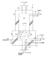
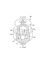
図4及び図5は、予熱器2と同様の灰除去手段を有する改質器3の一例を示している。すなわち、この改質器3は、上下方向に沿う円筒状の上側ヒートキャリア通路30と、この上側ヒートキャリア通路30の下方に連続する漏斗状(逆さ裁頭円錐台状。下側に向かうにつれて径が小さくなる形状であればよい。)の下側ヒートキャリア通路31とを有し、上側ヒートキャリア通路30上面の中央部に供給口30i、下側ヒートキャリア通路31下端にガス導入兼ヒートキャリア排出口31x、上側ヒートキャリア通路30の側面に改質ガス排出口30x、及び下側ヒートキャリア通路31下端部に連通する水蒸気注入口37をそれぞれ有しているものである。
4 and 5 show an example of the reformer 3 having the same ash removal means as the
改質器3では、予熱器2で十分に加熱されたヒートキャリアが上部供給口30iから供給され、ある程度の堆積状態を維持しながら上側及び下側ヒートキャリア通路30,31を下降しつつ、改質器3内を改質反応温度に維持する。この温度条件下で、改質器3内に導入される熱分解ガス及び水蒸気が前述の改質反応を起こし、水素高含有の改質ガスが生成し、改質ガス排出口30xを介してガス処理・利用設備へ供給される。
In the reformer 3, the heat carrier sufficiently heated by the
特徴的には、図示例の改質器3では、下側ヒートキャリア通路31は、パンチングメタル等のように多数の透過孔32nが全面に形成された漏斗状部材32により形成されている。漏斗状部材32の透過孔32nの寸法は、灰・ダストDは通過するがヒートキャリアは通過しないように設定されるとともに、漏斗状部材32の外側を取り囲むように環状スペース33が形成され、この環状スペース33の側面から外部に連通する灰・ダストの抜出口35が形成されている。漏斗状部材32の透過孔32nは灰・ダスト取り込み口となり、環状スペース33が灰・ダスト取り込み口32nの全てに連通する灰・ダスト落としスペースとなる。このような灰・ダスト取り込み口32n、灰・ダスト落としスペース33、及び抜出口35を有することにより、予熱器2で除去仕切れない灰を、改質器3で除去することができ、改質器3内や改質器3と熱分解器4との間の経路における灰の蓄積を効果的に防止できる。
Characteristically, in the reformer 3 of the illustrated example, the lower
漏斗状部材32はニッケル合金等の耐熱金属又はアルミナセラミックス等の耐熱セラミックスにより、また、上側ヒートキャリア通路30及び環状スペース33の周壁は耐熱セラミックス材により形成することができ、改質器3の外面は鉄皮により形成することができる。
The funnel-shaped
漏斗状部材32の透過孔32nの形状や寸法等、灰・ダストの抜出口35の位置や向き等は、予熱器2の場合と同様の改変が可能である。また、予熱器2の場合と同様に、抜出口35からの灰・ダストDの取り出しを容易にするために、灰・ダスト落としスペース33に連通する吹き込み口36を設け、灰・ダスト落としスペース33に圧縮空気(圧縮空気に代えて不活性ガスを用いても良い。以下同じ。)を吹き込んで抜出口35から排出するように構成することもできる。改質器3における圧縮空気による灰の排出はガス化運転を行っていないときに実施する。灰の排出を行う場合に、改質器3内温度を低下させないために、供給する圧縮空気を、例えば熱風生成装置1への供給空気と同様の廃熱との熱交換等、適宜の加熱手段により予め改質器3内温度又は近傍まで加熱してから供給することができる。圧縮空気吹き込み口36の位置や向き等は、予熱器2の場合と同様の改変が可能である。図示例では、予熱器2と同様の吹き込み口配置に対してさらに両側の吹き込み口36間の中央に吹き込み口36を追加している。
The position and orientation of the ash /
(分離機)
分離機5は特に限定されるものではなく、回転篩、振動篩等を好適に用いることができる。このようなスクリーンによる分離機5を用いる場合、熱分解後のチャーの寸法がヒートキャリアより十分に小さければ、ヒートキャリアより小さいチャーのみを通すスクリーンを用いることにより、ヒートキャリアとチャーとを確実に分離できる。しかし、現実には、有機物質原料の粒径を破砕等により揃えるとしても限界があり、ヒートキャリアより大きなチャーの発生を避けえず、この大きな塊状のチャーがヒートキャリアとともに予熱器2に送られ、予熱器2内で燃焼して灰が発生してしまう。しかも、このようにして発生した灰は、予熱器2の排気に伴い排出されるよりも、予熱器2内、改質器3内等、ヒートキャリアの循環経路内に堆積し易い。
(Separator)
The separator 5 is not particularly limited, and a rotary sieve, a vibrating sieve, or the like can be suitably used. In the case of using the separator 5 using such a screen, if the size of the char after pyrolysis is sufficiently smaller than the heat carrier, the heat carrier and the char can be reliably connected by using a screen that allows only the char smaller than the heat carrier to pass through. Can be separated. However, in reality, there is a limit even if the particle size of the organic material raw material is made uniform by crushing or the like, and generation of char larger than the heat carrier is inevitable, and this large lump of char is sent to the
そこで、図8に示すように、分離機5として、ヒートキャリアと等しい粒径を有する第1固形物(主にヒートキャリア)、第1固形物より粒径が小さい第2固形物(主に小さいチャー)、並びに第1固形物より粒径が大きい第3固形物(主に大きいチャー)の三種類に分離するものを用い、分離機5で分離した第1固形物、第2固形物及び第3固形物のうち、第1固形物は移送装置6により予熱器2に返送し、第2固形物及び第3固形物は熱風生成装置1に供給するように構成するのも好ましい形態である。
Therefore, as shown in FIG. 8, as the separator 5, the first solid having a particle size equal to that of the heat carrier (mainly heat carrier) and the second solid having a particle size smaller than the first solid (mainly small). Char) and a third solid having a particle size larger than that of the first solid (mainly large char), and the first solid, the second solid and the second solid separated by the separator 5 Of the three solids, the first solid is returned to the
分離機5において三種類の粒径の固形物に分離し、ヒートキャリアより大きなチャーを、ヒートキャリアより小さなチャーとともに熱風生成装置1に送るように構成し、ヒートキャリア循環経路内の灰の堆積を抑制するのは好ましい。なお、現実には厳密な分離は困難であり、ある程度のチャーはヒートキャリアとともに予熱器2に供給され、予熱器2内で灰を発生させることになるため、前述の灰の除去は極めて有効な手段である。
The separator 5 is separated into solids of three kinds of particle sizes, and is configured to send char larger than the heat carrier to the hot-air generating device 1 together with char smaller than the heat carrier. It is preferable to suppress. In practice, strict separation is difficult, and a certain amount of char is supplied to the
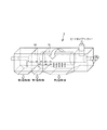
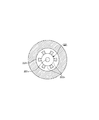
分離機5の形態は特に限定されるものではないが、例えば図示のような、第1固形物及び第2固形物は通すが第3固形物は通さない円筒状内側スクリーン50と、第2固形物は通すが第1固形物及び第3固形物は通さない、内側スクリーン50より大径の円筒状外側スクリーン51とを有する、2段スクリーンタイプの回転篩5を用いることができる。この回転篩5は、各スクリーン50,51内に供給された分離対象物が、各スクリーン50,51の軸心が水平方向に対して僅かに傾斜していること(これとともに又はこれに代えて、スクリーン50,51の内周面に螺旋方向に沿う羽根を突出させ、この羽根がスクリーン50,51の回転に伴い回転することにより、スクリューコンベアのように分離対象物が移送される構成としても良い。)、並びに各スクリーン50,51が軸心周りに回転されることにより、各スクリーン50,51の回転方向及び軸心の傾斜方向下側に移動しつつ、各スクリーン50,51を通過するものと、通過しないものとに分離されることを基本原理とするものである。そして、本例では、内側スクリーン50の一端側に、分離対象であるチャー及びヒートキャリアを供給すると、そのうち第1固形物及び第2固形物は内側スクリーン50を通過して外側スクリーン51内に供給され、第3固形物は内側スクリーン50を通過せずに内側スクリーン50の他端側に移動し、内側スクリーン50の他端側開口より回収され、外側スクリーン51内に供給された第1固形物及び第2固形物のうち、第2固形物は外側スクリーン51を通過して回収され、第1固形物は外側スクリーン51を通過せずに外側スクリーン51の他端側に移動し、外側スクリーン51の他端側開口より回収されるようになっている。
The form of the separator 5 is not particularly limited. For example, as shown in the figure, a cylindrical
(熱分解器)
ヒートキャリアより大きなチャーは、分離機5において三種類の粒径に分離することでも解決できるが、分離機5のコストや設置面積が嵩むという問題点がある。そこで、図6及び図7に示すように、熱分解器4におけるヒートキャリアの排出口41xは、ヒートキャリアと等しい粒径を有する第1固形物、並びに第1固形物より粒径が小さい第2固形物は通すが、第1固形物より粒径が大きい第3固形物は通さないスクリーン42で覆うのも好ましい形態である。より詳細には、図示例の熱分解器4は、上下方向に沿う円筒状の上側通路40と、この上側通路40の下方に連続する漏斗状(逆さ裁頭円錐台状。下側に向かうにつれて径が小さくなる形状であればよい。)の下側通路41とを有し、上側通路40上面の中央部に供給口40i、下側通路41下端に、スクリーン42で覆われた排出口41x、下側通路41の側面に水蒸気吹き込み口44をそれぞれ有しているものである。
(Pyrolyzer)
Chars larger than the heat carrier can be solved by separating them into three types of particle sizes in the separator 5, but there is a problem that the cost and installation area of the separator 5 increase. Therefore, as shown in FIGS. 6 and 7, the heat
このような排出口スクリーン42を設けることにより、ヒートキャリアより大きなチャーをスクリーン42で止めて熱分解器4から排出させず、ヒートキャリア及びヒートキャリアより小さなチャーのみ、スクリーン42を通過させることができ、分離機5によらずに(つまり、ヒートキャリアより小さいチャーのみを通す篩装置のように簡素な分離機5を用いても)、ヒートキャリアより大きなチャーが予熱器2に送られるのを防止できる。しかも、スクリーン42で止められたヒートキャリアより大きなチャーは、熱及びヒートキャリアの移動による外力を受けて砕けていくため、最終的にはヒートキャリア以下の寸法となってスクリーン42を通過するため、熱分解器4の排出口が閉塞することもない。
By providing such a
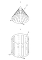
排出口スクリーン42の形状等は適宜定めることができ、平坦なパンチングメタルであっても良いが、図9(a)に示すように、排出口41x側に向かうにつれて直径が拡大する傘状(図示例では円錐状となっているが角錐状、ドーム状等にすることもできる)体の側面に、排出口41x側に向かうにつれて開口幅が拡大する通過孔42n(図示例では二等辺三角形状となっているが滴状等の適宜の形状とすることもできる)を周方向に所定の間隔で設けたものが好適である。このような傘状スクリーン42においては、熱分解器4内を下降する固形物がスクリーン42の側面の通過孔42nにスムーズに移動することができる。また、このスクリーン42の側面の通過孔42nは、排出口側に向かうにつれて開口幅が拡大する形状となっているため、スクリーン42側面に沿って接触しながら下降する固形物は、通過孔42nに引っ掛かり難く、円滑な分離が可能となる。
The shape and the like of the
この他にも、例えば図9(b)に示すように、通過孔を有しない上面と、上下方向に沿って所定幅で延在する通過孔42nが周方向に間隔を空けて形成された周面と、排出口41xに連通する開口底面とを備えた円筒状のスクリーン42を用いることもできる。
In addition to this, for example, as shown in FIG. 9B, an upper surface that does not have a passage hole and a
他方、排出口スクリーン42を設ける場合、分離機5としては、第1固形物及び第2固形物の二種類に分離するものを用い、分離機5で分離した第1固形物及び第2固形物のうち、第1固形物は移送装置6により予熱器2に返送し、第2固形物は熱風生成装置1に供給するように構成すると、設備がより簡素となるため好ましい。しかしもちろん、前述の三種類に分離するものを用いても、多重分離による分離性能向上効果はもたらされる。この場合における分離機5の形態は特に限定されるものではないが、例えば図10に示されるような、第2固形物は通すが第1固形物は通さない円筒状スクリーン52を有する回転篩5を用いることができる。この回転篩5において、スクリーン52の一端側に、分離対象であるチャー及びヒートキャリアを供給すると、スクリーン52の軸心が水平方向に対して僅かに傾斜していること、(これとともに又はこれに代えて、スクリーン50,51の内周面に螺旋方向に沿う羽根を突出させ、この羽根がスクリーン50,51の回転に伴い回転することにより、スクリューコンベアのように分離対象物が移送される構成としても良い。)、並びにスクリーン52が軸心周りに回転されることにより、第2固形物はスクリーン52を通過して回収され、第1固形物は外側スクリーン52を通過せずに外側スクリーン52の他端側に移動し、外側スクリーン52の他端側開口より回収されるようになっている。
On the other hand, when the
(高速昇温方法)
次に、図14に示されるシステム運用時の温度変化を参照しつつ、本発明の特徴部分について、(a)コールドスタートにおける高速昇温の応用、(b)待機運転、(c)ホットスタートにおける高速昇温の応用、(d)過熱抑制操作、(e)リセット操作、及び(f)後処理運転の順に説明する。
(Fast heating method)
Next, referring to the temperature change during system operation shown in FIG. 14, the features of the present invention are as follows: (a) Application of high-speed temperature rise in cold start, (b) Standby operation, (c) Hot start The application will be described in the order of application of high-speed temperature rise, (d) overheat suppression operation, (e) reset operation, and (f) post-processing operation.
なお、以下の説明において、予熱器2内温度、予熱器2からの排ガス温度、改質器3内温度、熱分解器4内温度は、それぞれ温度計2t,2x,3t,4tにより検出し、監視することができる。また、予熱器2内温度とは、図示位置からも分るとおり、予熱器2内の下部の温度(つまり予熱が完了して改質器3に向けて排出される前のヒートキャリアの温度に等しい)を意味する。さらに、ヒートキャリアの循環の停止は、各セグメントバルブ2b,3b,4b,6bを閉じるとともに移送装置6を停止することにより行うことができ、循環の開始は、各セグメントバルブ2b,3b,4b,6bを各所定の開閉頻度で開閉駆動するとともに移送装置6を起動することにより行うことができる。また、有機物質原料の供給開始及び停止は、原料供給系14,17の起動及び停止により行うことができ、その際に必要となる他の設備の起動及び停止も行われる。また、熱風供給の開始及び停止は、熱風供給生成装置1への燃料供給の開始及び停止、並びにこれに伴う着火及び消火により行うことができ、その際に必要となる他の設備の起動及び停止も行われる。
In the following description, the temperature inside the
(a)コールドスタートへの応用。
図14及び図15に示されるように、コールドスタートは、システム全体が気温レベルにある状態からのシステム起動である。通常、この状態では計測機器以外は全て停止状態にある。この状態から、熱分解器4内温度が熱分解器定常運転温度に達するまでは従来同様にして昇温を行う。すなわち、先ず、熱風生成装置1において補助燃料を燃焼させて熱風を生成し、熱風温度を徐々に上げる。予熱器2内の温度が所定温度に達した時点、例えば予熱器2から出て行く排ガス(予熱器排ガス)が200℃を超えた時点からヒートキャリアの循環を開始し、予熱器2内で暖められたヒートキャリアはその下に設置された改質器3、熱分解器4へと順に落とされた後、再び予熱器2に戻されるようになる。このヒートキャリアの循環に伴って、改質器3、熱分解器4、分離機など、循環経路に熱が供給し、システム全体が昇温されていく。
(A) Application to cold start.
As shown in FIGS. 14 and 15, the cold start is a system start-up from a state where the entire system is at an air temperature level. Normally, in this state, all devices other than the measuring device are in a stopped state. From this state, the temperature is raised in the same manner as before until the temperature in the
特徴的には、熱分解器4の温度が熱分解器定常運転温度、例えば600℃を超えた時点で、原料供給を開始するのではなく、原料供給は停止したまま、ヒートキャリアの循環を停止し、この状態で熱風生成装置1から予熱器2へ熱風供給を継続する、予熱器昇温運転を行う。この予熱器昇温運転においては、熱風生成装置1に対するチャーの供給は不可能であるため、熱風生成装置1は補助燃料により運転を行う。この予熱器昇温運転により、図15に示されるように予熱器2内の温度は上昇傾向となり、ある程度の時間を経て予熱器定常運転温度(例えば1000℃)に達する。一方、改質器3及び熱分解器4は、ヒートキャリアの循環停止に伴い熱が供給されなくなるため放熱冷却が始まり、温度が低下していく。よって、熱分解器4の温度が機器制限温度を超えることもない。
Characteristically, when the temperature of the
そして、予熱器2内の温度が所定の予熱器定常運転温度に達したならば、有機物質原料の供給停止状態及び熱風供給状態を継続しつつ、ヒートキャリアの循環を開始する。これにより、図15に示されるように、改質器3内の温度及び熱分解器4内の温度が速やかに上昇し、所定の改質器定常運転温度及び熱分解器定常運転温度にそれぞれ達する。改質器3内の温度及び熱分解器4内の温度が所定の改質器定常運転温度及び熱分解器定常運転温度にそれぞれ達したならば、直ちに又は後述の待機運転を経て、有機物質原料の供給を開始し、定常運転に移行する。
When the temperature in the
このような手法によって、ヒートキャリアの循環再開と共にその保有熱が改質器3及び熱分解器4に供給され、各器の定常運転温度の高低関係と加熱順番との関係の影響もあり、図15に示されるように、各部の温度がバランス良く、迅速に上昇する。その結果、従来よりも燃料無駄が無く、昇温時間が短くなる。
With such a technique, the retained heat is supplied to the reformer 3 and the
なお、急加熱運転の開始当初は、ヒートキャリア循環の再開により、予熱器2に移送装置6から冷えた熱媒体が入り込んでくるため、予熱器2内温度が低下し過ぎるおそれがある。そこで、急加熱運転におけるヒートキャリアの循環開始と同時又はその直前もしくは直後に、予熱器2に対する熱風供給量及び供給熱風温度の少なくとも一方を増加し、予熱器2の温度低下を緩和又は防止する操作を行うのが好ましく、特に、熱風温度を一定にしつつ熱風供給量を増加することにより、予熱器2の温度低下を防止するのが好ましい。後者の場合、熱風生成装置1における補助燃料の供給量及び燃焼用空気の供給量を、生成熱風の温度が変化しないように増加させる。熱風生成装置1が燃焼排ガスの温度を指標にしたオート運転を行っている場合は、自動的に補助燃料の供給量がコントロールされるので、燃焼用空気量を増やす操作だけでよい。この操作は急加熱運転である限り、後述のホットスタート等にも利用できるものである。
At the beginning of the rapid heating operation, the heat medium cooled from the
(b)待機運転
DSS運転で、例えば夕方に定常運転を終え、翌日のビジネスタイムから定常運転に入る場合等、次の操業が予定時刻から確実に開始できるようにプラントを定常運転温度のままの待機状態に置くことが望ましい場合がある。これに反して、一旦プラントの火を消すと、外気との温度差が大きいために高温部ほど急速に冷却し、迅速に定常運転温度に戻すことは不可能になる。
(B) Standby operation In the DSS operation, for example, when the normal operation is finished in the evening and the normal operation starts from the next day's business time, the plant is kept at the normal operation temperature so that the next operation can be surely started from the scheduled time. It may be desirable to put it on standby. On the other hand, once the plant fire is extinguished, the temperature difference from the outside air is large, so it becomes impossible to quickly cool the higher temperature portion and quickly return to the steady operating temperature.
そこでこのような場合、原料供給を停止している状態から、原料供給を開始するまでの間、次の(い)〜(は)の少なくとも一つの操作により、予熱器内の温度、改質器内の温度、及び熱分解器内の温度を、予熱器定常運転温度、改質器定常運転温度、及び熱分解器定常運転温度にそれぞれ維持する、待機運転を行い、何時でも原料供給可能な温度状態を保つのは好ましい。
(い)ヒートキャリアの循環を一時的又は連続的に停止する。これにより、各機器の温度を放熱により下げることができる。
(ろ)ヒートキャリアの循環を一時的又は連続的に実行する。これにより、各機器の温度を熱供給により上げることができる。
(は)予熱器2に対する熱風供給量及び供給熱風温度のうち少なくとも一方を増減する。これにより、ヒートキャリアの加熱の程度を変化させることができる。
Therefore, in such a case, the temperature in the preheater, the reformer is changed by at least one of the following (ii) to (ha) from the state where the raw material supply is stopped until the raw material supply is started. The temperature at which the raw material can be supplied at any time by performing standby operation to maintain the internal temperature and the internal temperature of the thermal cracker at the preheater steady operation temperature, the reformer steady operation temperature, and the thermal cracker steady operation temperature, respectively. It is preferable to keep the state.
(Ii) Stop the heat carrier circulation temporarily or continuously. Thereby, the temperature of each apparatus can be reduced by heat radiation.
(B) The heat carrier is circulated temporarily or continuously. Thereby, the temperature of each apparatus can be raised by heat supply.
(Ha) Increase or decrease at least one of the hot air supply amount and the supply hot air temperature to the
本発明では、この高温環境を維持する運転方法を、待機運転と呼び、原料供給系と生成ガス系統の機器を停止した状態で、熱風生成装置1の運転及び熱風生成装置1から予熱器2への燃焼排ガスの供給、ヒートキャリアの循環を継続する運転方法である。図14に示される例では、コールドスタートと定常運転との間、及び後述するホットスタートと定常運転との間でこの待機運転を行っている。
In the present invention, this operation method for maintaining the high temperature environment is called standby operation, and the operation of the hot air generator 1 and the hot air generator 1 to the
例えば、DSSの場合は、水蒸気供給停止、誘引送風機11停止、洗浄水循環停止と順に操作した後、熱風供給とヒートキャリアの循環を停止せずに、予熱器2、改質器3、熱分解器4への熱供給を継続して温度低下を防ぎ、何時でも原料供給を開始できる待機状態に保つようにする。操業停止が夕方で、翌朝通常のビジネスタイムに操業開始する場合、概ね15時間の待機運転となる。また、金曜日夕方停止から翌週月曜日操業開始の場合は、63時間程度の待機運転となる。さらに、昇温が原料供給開始時刻よりも早く、定常運転温度に到達した場合にも、この運転方法により、温度を維持することが可能となる。
For example, in the case of DSS, after operating in order of water vapor supply stop,
この待機運転の場合、予熱器2、改質器3、熱分解器4のいずれかの内部温度が、必要以上に上昇することがあるが、そのような場合に備えて、温度上昇を抑えるための後述する過熱抑制操作を実施するのは好ましい。
In this standby operation, the internal temperature of any one of the
(c)ホットスタートにおける高速昇温の応用
ガス化システムを運用していく上では一時的に操業を停止し、労力を軽減することが望まれる場合がある。代表的な例としては、生成ガスを用いて発電を行い、売電を行うにあたり、電気買取価格が低く人件費が高い夜間の収益が極端に低下する場合や、週末、連休に操業を休む場合を挙げることができる。このような一時的な操業停止において、システムをある程度まで冷却してしまうと、システムを再びガス化可能な状態まで昇温するのには長時間を要する。
(C) Application of high-speed temperature increase in hot start In operating a gasification system, it may be desired to temporarily stop operation and reduce labor. As a typical example, when generating electricity using the generated gas and selling power, the nighttime profits with low electricity purchase prices and high labor costs are drastically reduced, or the operation is closed on weekends and consecutive holidays. Can be mentioned. In such a temporary shutdown, if the system is cooled to some extent, it takes a long time to raise the temperature of the system to a state where it can be gasified again.
例えば、本システムが、連休前に原料供給を停止し、数日後の連休明けから原料供給を開始する場合、一旦熱風送風まで停止するシステム全停止の状態にすると、熱分解器の内部温度は気温が2℃から4℃の冬季の計測では24時間で500℃から100℃に冷却する。予熱器2など最も熱が残る部分でも、5日から6日でほぼ気温程度まで冷却する。一旦システムが気温程度まで冷却してしまうと、コールドスタートの昇温となるため、その昇温には長時間を要し、連休明けから昇温に入っても直ぐにはガス化を開始することはできないこととなる。この場合、待機運転をすることも考えられるが、操業停止期間が長過ぎるため、不経済な運転となってしまう。
For example, if this system stops the supply of raw materials before consecutive holidays and starts the supply of raw materials after the consecutive holidays several days later, once the system is stopped until hot air blowing is stopped, the internal temperature of the pyrolyzer However, in winter measurements from 2 ° C to 4 ° C, it cools from 500 ° C to 100 ° C in 24 hours. Even in the
そこで、システムを一時的に停止する場合、定常運転から操業を完全に停止せず、図14に示されるように保温運転に移行し、しかる後に保温運転から操業を再開する方法も提案する。定常運転では、予熱器2内の温度、改質器3内の温度、及び熱分解器4内の温度が、予熱器定常運転温度、改質器定常運転温度、及び熱分解器定常運転温度にそれぞれ達している状態で、予熱器に対する熱風の供給、ヒートキャリアの循環、及び有機物質原料の供給を行っている。この状態から、保温運転に入り、原料供給停止の後、ガス発生終了を確認して、改質器3に対する水蒸気供給、改質器3からの誘引送風機11による生成ガス送出、及びガス処理・利用設備をそれぞれ停止するが、熱風発生装置1の運転及び熱風発生装置1から予熱器2への燃焼排ガスの供給は継続する。原料供給停止に伴い、熱風発生装置1に対するチャーの供給は数時間で途絶えるため、熱風発生装置1は補助燃料により運転を継続する。
Therefore, when the system is temporarily stopped, a method is proposed in which the operation is not completely stopped from the steady operation, but is shifted to the heat insulation operation as shown in FIG. 14, and then the operation is resumed from the heat insulation operation. In the steady operation, the temperature in the
そして、エネルギー効率良く保温を行うために、予熱器2に対する供給熱量の増減及びヒートキャリアの循環速度の増減の少なくとも一方を行い、予熱器2内の温度を予熱器定常運転温度よりも低く且つ所定の下限温度以上、熱分解器4内の温度を熱分解器定常運転温度よりも低く且つ所定の下限温度以上、及び改質器3内の温度を改質器定常運転温度よりも低く且つ所定の下限温度以上にそれぞれ保持する。この保温運転は、次の原料開始の所定時間前(例えば24時間前)にホットスタート高速昇温運転に入ることを前提としており、予熱器2、改質器3、熱分解器4の温度を下限温度付近に保つことが目的である。通常の場合、予熱器2、改質器3、熱分解器4を迅速に(例えば6〜7時間程度で)定常運転温度に昇温するためには、予熱器2の下限温度は750℃とし、改質器3の下限温度は600℃とし、熱分解器4の下限温度は500℃とするのが望ましい。
And in order to perform heat insulation efficiently, at least one of increase / decrease in the amount of heat supplied to the
保温運転において各機器の温度を低下させる場合、熱風温度を維持したまま予熱器2への供給熱量を減らすのが望ましく、特に、熱風発生装置1への補助燃料供給量及び燃焼用空気の送風量の少なくとも一つを減らすのが望ましい。もちろん、熱風供給量を維持したまま供給熱風温度を低下しても良いし、熱風供給量及び供給熱風温度の両方を低下させても良い。また、ヒートキャリアの循環速度を標準より遅くしたり、上記下限温度に各反応器が温度低下するまで熱風送風を停止したり、あるいは熱風送風及びヒートキャリアの循環の両者を停止し、各反応器が下限温度まで低下したら再開するといった方法をとることもできる。
When the temperature of each device is lowered in the heat insulation operation, it is desirable to reduce the amount of heat supplied to the
以上の熱風とヒートキャリアに関する操作で、予熱器2、改質器3、熱分解器4は、徐々に温度低下傾向に入る。この時には、基本的に過熱の心配は無くなっているが、念のため、各器の温度低下を監視するのが好ましい。熱分解器4が、熱分解機定常運転温度を超える事態が発生したときには、ヒートキャリアの循環を一時停止して、予熱器2に送る熱風の温度及び風量の少なくとも一つを低減し、予熱器2出口のヒートキャリアの温度を下げる操作を行い、熱分解器4の温度が熱分解機定常運転温度以下に冷却してからヒートキャリアの循環を再開する。
The
一方、いずれかの器の温度が下限温度に近づく又は下回ったときには、熱風の量ないし温度を増やす方向に操作して、予熱器2から出て行くヒートキャリアの温度を高め、ヒートキャリアの循環を早めて各器への供給熱量を増加する。保温運転においていずれかの反応器の温度が一時的に下限温度を下回ることがあっても、次述の予熱器昇温運転前に下限温度に回復すれば保温運転の目的は達せられる。
On the other hand, when the temperature of any vessel approaches or falls below the lower limit temperature, the temperature of the heat carrier that goes out of the
操業の再開に際しては、保温運転からヒートキャリアの循環を停止して前述の予熱器昇温運転に移行する。そして、予熱器2内の温度が所定の予熱器定常運転温度に達した後に、ヒートキャリアの循環を再開し、改質器3内の温度及び熱分解器4内の温度が所定の改質器定常運転温度及び熱分解器定常運転温度にそれぞれ達するまで前述の急加熱運転を行う。このヒートキャリアの循環再開によって、改質器3と熱分解器4の温度は、一気に定常運転温度に達する。より詳細には、予熱器昇温運転が概ね数時間で終了し、その間、改質器3と熱分解器4が放熱冷却で温度低下を起こすものの、ヒートキャリアの循環再開で改質器3には予熱器2から1000℃前後のものが落下、熱分解器には600℃程度のものが改質器から落下するため、改質器2も熱分解器3もほぼ同時に適正温度に到達する。
When the operation is resumed, the heat carrier circulation is stopped from the heat retaining operation, and the operation proceeds to the above-described preheater temperature increasing operation. Then, after the temperature in the
しかる後に有機物質原料の供給を再開し、ガス化を開始する。このように保温運転を行うことによりシステムを一定温度以上に保ち、その後に本発明の予熱器昇温運転及び急加熱運転を経て原料供給を再開することにより、エネルギー消費を抑えつつシステムの再開を速やかに行うことができるようになる。 Thereafter, the supply of the organic material is resumed and gasification is started. In this way, the system is kept above a certain temperature by performing the heat insulation operation, and then restarting the system while suppressing energy consumption by restarting the raw material supply through the preheater temperature raising operation and the rapid heating operation of the present invention. It will be possible to do it promptly.
保温運転の際、予熱器2の内部温度が700℃、改質器3の内部温度が600℃、熱分解器4の内部温度が500℃付近にあり、その温度からそれぞれ1000℃、950℃、600℃の定常運転温度まで昇温する場合を想定すると、保温運転から予熱器昇温運転への移行は、原料供給開始予定時刻の6〜7時間前から開始するのが適当である。すなわち、ヒートキャリアの各反応器での貯留量は、大体ヒートキャリア全量の3分の1程度であり、仮にヒートキャリアの全量を4.7トンとし、仮にヒートキャリアの循環量を時間当たり500キログラムとすると、予熱器2のヒートキャリアが改質器3に全量移動する時間は、約3時間である。従って、予熱器昇温のスタートから定常運転温度到達まで一連の作業時間は、予熱器昇温の約3時間と合わせ、凡そ6時間である。原料投入予定時刻の約6〜7時間前から高速昇温に入れば原料投入予定時刻までには十分昇温できる。
During the heat insulation operation, the internal temperature of the
(d)過熱抑制操作
例えば予熱器昇温運転中はヒートキャリアの循環を停止しているため、予熱器2内温度が予熱器定常運転温度に達し、さらに温度が上昇して予熱器の排ガス温度が機器制限温度を超えるおそれがある。また、待機運転中も、既に各機器が定常運転温度に達しているため、さらに温度が上昇して予熱器の排ガス温度が機器制限温度を超えるおそれがある。もちろん、急加熱運転中や定常運転中もそのおそれが無いわけではない。よって、予熱器2内温度が予熱器定常運転温度に達し、予熱器2の排ガス温度が機器制限温度(例えば550℃程度)を超えたとき、次の(イ)〜(ニ)の少なくとも一つの過熱抑制操作を実行するのが望ましい。
(イ)ヒートキャリアの循環が停止しているとき、一時的に、ヒートキャリアの循環を開始する。これにより、冷えたヒートキャリアを予熱器2内に供給して予熱器2を冷却することができる。
(ロ)一時的又は連続的に、予熱器2に対する熱風供給量及び供給熱風温度のうち、供給熱風温度は維持したまま熱風供給量を減少させる。これにより予熱器2に対する供給熱量を減少させ、放熱による冷却効果を利用し、冷却することができる。熱風生成装置1が燃焼排ガスの温度を指標にしたオート運転を行っている場合は、自動的に補助燃料の供給量がコントロールされるので、燃焼用空気量を減らす操作だけで、温度は下がらずに熱量が減る。
(ハ)一時的に、予熱器2への熱風供給を停止する。これにより、予熱器2に対する供給熱量を無くし、放熱による冷却効果を最大限利用して冷却することができる。
(ニ)一時的に、予熱器2に対して冷却用空気を送風する。これにより、予熱器2の強制冷却を行うことができる。冷却用空気としては、熱風生成装置1に供給される燃焼用空気をそのまま(図示例の場合、予熱器排ガス温度に近い温度となっている)用いることができる。この操作は、放熱冷却を待ちきれない緊急時に適用するものである。
このような過熱抑制操作を実行することによって予熱器2の温度低下を抑えつつ、運転継続による予熱器2の過熱を防止できるようになる。この操作は、温度の超過度合いに応じて、超過度合いが大きいときほど多い数の操作を組み合わせて適用し、かつその際に(イ)〜(ニ)の順に適用するのは望ましい。例えば、一時的又は連続的に(イ)のヒートキャリアの循環を再開し、それでも予熱器2内温度が下がらないときには、予熱器2に対する供給熱風温度は維持したまま熱風供給量を減少させる(ロ)〜(ハ)の操作を行うことによって、予熱器昇温運転等の継続による予熱器2の過熱を抑制する。ただし、それでもなお、予熱器2の昇温を抑えられない場合もありうる。よって、そのような場合には、上述の(二)のような予熱器冷却行程を行うのが好ましい。
(D) Overheat suppression operation For example, since the circulation of the heat carrier is stopped during the preheater heating operation, the temperature in the
(B) When the circulation of the heat carrier is stopped, the circulation of the heat carrier is temporarily started. Thereby, the
(B) Temporarily or continuously, among the hot air supply amount and the supply hot air temperature to the
(C) Temporarily stop the supply of hot air to the
(D) Temporarily blow cooling air to the
By performing such an overheat suppression operation, it is possible to prevent overheating of the
(e)リセット操作
本システムは、ヒートキャリアをシステム内で循環させ、予熱器2での蓄熱と改質器3と熱分解器4での放熱を利用して、熱分解器4の中での有機物質の熱分解と改質器3の中での水蒸気改質を行うシステムであるが、熱分解器4に原料が供給され過ぎると、吸熱反応と水分の蒸発等により、熱分解器4内でヒートキャリアの温度低下が起こり、この温度低下が許容範囲を超えると、図14に示されるように、ヒートキャリア温度が循環の度に下がる温度低下スパイラルに入る。例えば、通常の場合、熱分解器4内のヒートキャリア温度として許容できる下限温度はおよそ500℃であり、この温度を下回ると、予熱器2に戻る時には400℃以下となり、予熱器2での昇温の限界もあって、温度低下スパイラルという悪循環に陥り、ヒートキャリアを定常運転温度に戻せなくなる。そして、このような低温状態になると、改質器3の温度も水蒸気改質の出来る温度ではなくなり、水蒸気改質反応は消え、単なる熱分解だけのガス製造が続いているだけとなり、生成ガスの水素濃度は低くなる。
(E) Reset operation This system circulates a heat carrier in the system and uses heat storage in the
そこで、このような温度低下の悪循環から抜け出すための手法として、次のようなリセット操作も提案する。すなわち、予熱器2内の温度、改質器3内の温度、及び熱分解器4内の温度が、予熱器定常運転温度、改質器定常運転温度、及び熱分解器定常運転温度にそれぞれ達している状態で、熱風の供給、ヒートキャリアの循環、及び有機物質原料の供給を行う定常運転中に、熱分解器4内温度が熱分解器定常運転温度未満、特に下限温度未満となったとき、原料供給を停止し、熱風の送風を継続して予熱器昇温運転に入る。この予熱器昇温運転により、予熱器2内の温度が所定の予熱器定常運転温度に回復したならば、ヒートキャリアの循環を再開して急加熱運転に移行し、改質器3内の温度及び熱分解器4内の温度をそれぞれ所定の改質器定常運転温度及び熱分解器定常運転温度に一気に回復させる。
Therefore, the following reset operation is also proposed as a method for getting out of such a vicious cycle of temperature decrease. That is, the temperature in the
このリセット操作によって、各器の温度が定常運転温度に回復したら、温度低下悪循環の原因となった原料の供給量をリセット操作前よりも減らすように、原料供給系14,17の設定を変更してから原料供給を再開する。原料の供給量をどの程度減らすかは適宜定めることができるが、最初は大幅に減らし(概ね3分の1から4分の1に減らす)、そこから徐々に供給量を増やし、原料供給を継続しても熱分解器4の温度が下限温度以下に低下しない適正原料供給量に調整するのが好ましい。
When the temperature of each unit is restored to the steady operation temperature by this reset operation, the settings of the
(f)後処理運転
システムを停止する際、直ちにヒートキャリアの循環をも停止してしまうと、熱分解器4に滴下するタールの固化により多数のヒートキャリアが塊状に固まり、次のシステム開始の際にヒートキャリアの循環阻害をもたらすことがある。そこで、システムを停止するにあたり、熱分解器4に対する有機物質原料の供給を停止した状態で、ヒートキャリアの循環及び予熱器2への熱風供給を継続する、後処理運転を所定時間(例えば2時間以上)行い、しかる後に、ヒートキャリアの循環及び予熱器2への熱風供給をそれぞれ停止することも提案する。この後処理運転を行うことにより、熱分解器4においてタールが滴下しても熱風により加熱されたヒートキャリアが循環しているため、塊状に固化するといった事態は発生し難くなる。
(F) Post-processing operation When the system is stopped, if the heat carrier circulation is stopped immediately, a large number of heat carriers are solidified by the solidification of the tar dripped onto the
本発明は、木質バイオマス等の有機物質のガス化に利用できるものである。 The present invention can be used for gasification of organic substances such as woody biomass.
1…熱風生成装置、2…予熱器、3…改質器、4…熱分解器、5…分離機、6…移送装置。 DESCRIPTION OF SYMBOLS 1 ... Hot air production | generation apparatus, 2 ... Preheater, 3 ... Reformer, 4 ... Thermal decomposition device, 5 ... Separator, 6 ... Transfer device.
Claims (9)
前記ヒートキャリアを、前記予熱器、改質器、及び熱分解器の順に通した後、移送装置により再び予熱器に戻して循環させるとともに、前記熱分解器内に有機物質原料を供給し、前記改質器内に対して直接又は間接的に水蒸気を供給し、
前記熱分解器内では、前記有機物質原料を、加熱されたヒートキャリアと接触させることによりチャーと熱分解ガスとに熱分解し、熱分解ガスはヒートキャリアに対して向流接触しながら改質器へ供給し、
前記改質器では、前記熱分解ガスを前記ヒートキャリアにより加熱しつつ前記水蒸気と接触させることにより水素含有濃度を向上させたガスを生成し、
前記熱風生成装置では、熱風を生成して予熱器に供給し、
前記予熱器では、前記熱風生成装置から供給される熱風を、前記予熱器内を堆積状態で通過するヒートキャリア間に通して、ヒートキャリアと直接接触することによりヒートキャリアを加熱する、
ように構成した有機物質のガス化システムにおける高速昇温方法であって;
前記熱分解器に対する前記有機物質原料の供給、及び前記ヒートキャリアの循環をそれぞれ停止した状態で、前記熱風生成装置から前記予熱器へ熱風供給する、予熱器昇温運転を行い、
前記予熱器内の温度が所定の予熱器定常運転温度に達した後に、前記有機物質原料の供給停止状態及び前記熱風供給状態を継続しつつ、前記ヒートキャリアの循環を行う急加熱運転を、前記改質器内の温度及び熱分解器内の温度が所定の改質器定常運転温度及び熱分解器定常運転温度にそれぞれ達するまで行う、
ことを特徴とする有機物質のガス化システムにおける高速昇温方法。 A number of heat carriers for carrying heat, a preheater for heating the heat carrier, a reformer for performing steam reforming of the pyrolysis gas, and pyrolysis for pyrolyzing the organic material raw material And a hot air generator for generating hot air,
The heat carrier is passed through the preheater, the reformer, and the thermal decomposer in this order, and then returned to the preheater by the transfer device and circulated, and the organic material raw material is supplied into the thermal decomposer, Supplying steam directly or indirectly into the reformer,
In the pyrolyzer, the organic material is pyrolyzed into char and pyrolysis gas by bringing it into contact with a heated heat carrier, and the pyrolysis gas is reformed in countercurrent contact with the heat carrier. Supply
In the reformer, a gas having an improved hydrogen-containing concentration is produced by bringing the pyrolysis gas into contact with the water vapor while being heated by the heat carrier,
In the hot air generator, hot air is generated and supplied to the preheater,
In the preheater, the hot air supplied from the hot air generator is passed between the heat carriers passing through the preheater in a deposited state, and the heat carrier is heated by directly contacting the heat carrier.
A method of fast heating in an organic material gasification system configured as follows:
In the state where supply of the organic material raw material to the pyrolyzer and circulation of the heat carrier are stopped, hot air is supplied from the hot air generator to the preheater, and a preheater heating operation is performed.
After the temperature in the preheater reaches a predetermined preheater steady operation temperature, the rapid heating operation for circulating the heat carrier while continuing the supply stop state of the organic material and the hot air supply state, Until the temperature in the reformer and the temperature in the pyrolyzer reach the predetermined reformer steady-state operating temperature and the thermal cracker steady-state operating temperature, respectively.
A method for rapidly raising temperature in a gasification system for organic substances.
前記有機物質原料の供給及び前記ヒートキャリアの循環を行わずに、前記予熱器に対して熱風の供給を開始し、前記予熱器内温度が所定温度を超えた後に前記熱風供給を継続したまま前記ヒートキャリアの循環を開始し、
このヒートキャリアの循環により前記熱分解器内温度が熱分解器定常運転温度に到達した後に、前記予熱器昇温運転を開始し、
この予熱器昇温運転により、前記予熱器内の温度が所定の予熱器定常運転温度に達した後に、前記改質器内の温度及び熱分解器内の温度が所定の改質器定常運転温度及び熱分解器定常運転温度にそれぞれ達するまで前記急加熱運転を行い、しかる後に前記有機物質原料の供給を開始する、請求項1又は2記載の有機物質のガス化システムにおける高速昇温方法。 At the time of cold start, the preheater, the reformer, and the thermal cracker are heated from the air temperature state to the preheater steady operation temperature, the reformer steady operation temperature, and the thermal cracker steady operation temperature, respectively.
Without supplying the organic material raw material and circulating the heat carrier, start supplying hot air to the preheater, and the hot air supply continues after the preheater temperature exceeds a predetermined temperature. Started circulating the heat carrier,
After the temperature inside the pyrolyzer reaches the pyrolyzer steady operation temperature due to the circulation of the heat carrier, the preheater heating operation is started,
After the preheater temperature increasing operation, the temperature in the preheater reaches the predetermined preheater steady operation temperature, and then the temperature in the reformer and the temperature in the pyrolyzer are the predetermined reformer steady operation temperature. 3. The high-speed heating method in the organic material gasification system according to claim 1, wherein the rapid heating operation is performed until reaching a steady operation temperature of the pyrolyzer, and then the supply of the organic material raw material is started.
前記有機物質原料の供給を停止した状態で、前記予熱器に対する供給熱量の増減及び前記ヒートキャリアの循環速度の増減の少なくとも一方を行い、予熱器に対する熱風供給量及び供給熱風温度のうち少なくとも一方を低減し、且つ前記予熱器内の温度を前記予熱器定常運転温度よりも低く且つ所定の下限温度以上、前記熱分解器内の温度を前記熱分解器定常運転温度よりも低く且つ所定の下限温度以上、及び前記改質器内の温度を前記改質器定常運転温度よりも低く且つ所定の下限温度以上にそれぞれ保持する、保温運転に移行した後、
この保温運転から前記予熱器昇温運転に移行し、前記予熱器内の温度が所定の予熱器定常運転温度に達した後に、前記改質器内の温度及び熱分解器内の温度が所定の改質器定常運転温度及び熱分解器定常運転温度にそれぞれ達するまで前記急加熱運転を行い、しかる後に前記有機物質原料の供給を再開する、ホットスタートを行う、請求項1又は2記載の有機物質のガス化システムにおける高速昇温方法。 The temperature in the preheater, the temperature in the reformer, and the temperature in the thermal decomposer are the preheater steady operation temperature, the reformer steady operation temperature, and the thermal cracker steady operation temperature, respectively. From the steady operation of supplying hot air to the preheater, circulating the heat carrier, and supplying the organic material raw material,
In a state where the supply of the organic material raw material is stopped, at least one of increase / decrease in the amount of heat supplied to the preheater and increase / decrease in the circulation rate of the heat carrier is performed, and at least one of the hot air supply amount and the supply hot air temperature to the preheater is performed. The temperature in the preheater is lower than the steady operation temperature of the preheater and equal to or higher than a predetermined lower limit temperature, and the temperature in the thermal decomposer is lower than the steady operation temperature of the thermal decomposer and a predetermined lower limit temperature. After shifting to the heat retention operation, the temperature inside the reformer is lower than the reformer steady operation temperature and at or above a predetermined lower limit temperature,
After the temperature maintaining operation is shifted to the preheater temperature increasing operation and the temperature in the preheater reaches a predetermined preheater steady operation temperature, the temperature in the reformer and the temperature in the thermal decomposer are set to a predetermined value. The organic substance according to claim 1, wherein the rapid heating operation is performed until the steady state temperature of the reformer and the steady state temperature of the pyrolyzer are respectively reached, and then the supply of the organic material raw material is resumed, and a hot start is performed. Fast heating method in the gasification system.
(い)前記ヒートキャリアの循環の一時的又は連続的な停止、
(ろ)前記ヒートキャリアの循環の一時的又は連続的な実行、並びに
(は)前記予熱器に対する熱風供給量及び供給熱風温度のうち少なくとも一方の増減、
の少なくとも一つの操作により、前記予熱器内の温度、前記改質器内の温度、及び前記熱分解器内の温度を、前記予熱器定常運転温度、前記改質器定常運転温度、及び前記熱分解器定常運転温度にそれぞれ維持する、待機運転を行う、請求項1〜4のいずれか1項に記載のガス化システムにおける高速昇温方法。 The temperature in the preheater, the temperature in the reformer, and the temperature in the thermal decomposer are the preheater steady operation temperature, the reformer steady operation temperature, and the thermal cracker steady operation temperature, respectively. From the state where the raw material supply is stopped until the raw material supply is started,
(Ii) Temporary or continuous stop of circulation of the heat carrier,
(B) Temporary or continuous execution of circulation of the heat carrier, and (ha) increase or decrease of at least one of hot air supply amount and supply hot air temperature to the preheater,
The temperature in the preheater, the temperature in the reformer, and the temperature in the pyrolyzer are changed to the preheater steady operation temperature, the reformer steady operation temperature, and the heat by the at least one operation of The high-speed temperature rising method in the gasification system of any one of Claims 1-4 which performs standby operation | maintenance each maintained to a cracker steady operation temperature.
前記予熱器昇温運転を行い、前記予熱器内の温度が所定の予熱器定常運転温度に達した後に、前記改質器内の温度及び熱分解器内の温度が所定の改質器定常運転温度及び熱分解器定常運転温度にそれぞれ達するまで前記急加熱運転を行う、リセット操作を実行し、このリセット操作後に、リセット操作前よりも少ない供給量で前記有機物質原料の供給を再開する、
請求項1〜5のいずれか1項に記載の有機物質のガス化システムにおける高速昇温方法。 The temperature in the preheater, the temperature in the reformer, and the temperature in the thermal decomposer are the preheater steady operation temperature, the reformer steady operation temperature, and the thermal cracker steady operation temperature, respectively. When the temperature inside the pyrolyzer becomes less than the steady operation temperature of the pyrolyzer during steady operation in which the hot air is supplied, the heat carrier is circulated, and the organic material raw material is supplied. ,
After the preheater temperature increasing operation is performed and the temperature in the preheater reaches a predetermined preheater steady operation temperature, the temperature in the reformer and the temperature in the pyrolyzer are in a predetermined reformer steady operation. The rapid heating operation is performed until the temperature and the pyrolyzer steady operation temperature are reached, respectively, a reset operation is performed, and after the reset operation, the supply of the organic material raw material is resumed with a smaller supply amount than before the reset operation.
The high-speed temperature rising method in the gasification system of the organic substance of any one of Claims 1-5.
(イ)前記ヒートキャリアの循環が停止しているとき、一時的に、前記ヒートキャリアの循環を開始する、
(ロ)一時的又は連続的に、前記予熱器に対する熱風供給量及び供給熱風温度のうち、供給熱風温度は維持したまま熱風供給量を減少させる、
(ハ)一時的に、前記予熱器への熱風供給を停止する、
(ニ)一時的に、予熱器に対して冷却用空気を送風する、
の少なくとも一つの過熱抑制操作を実行する、
請求項1〜6のいずれか1項に記載の有機物質のガス化システムにおける高速昇温方法。 When the preheater internal temperature reaches the preheater steady operation temperature and the exhaust gas temperature of the preheater exceeds the equipment limit temperature, the following:
(I) When the circulation of the heat carrier is stopped, the circulation of the heat carrier is temporarily started.
(B) Temporarily or continuously, among the hot air supply amount and supply hot air temperature to the preheater, the supply hot air temperature is maintained and the hot air supply amount is decreased.
(C) Temporarily stopping the supply of hot air to the preheater,
(D) Temporarily blow cooling air to the preheater,
Performing at least one overheat suppression operation of
The high-speed temperature rising method in the gasification system of the organic substance of any one of Claims 1-6.
Priority Applications (1)
| Application Number | Priority Date | Filing Date | Title |
|---|---|---|---|
| JP2011066792A JP2012201769A (en) | 2011-03-24 | 2011-03-24 | Rapid heatup method for organic matter gasification system |
Applications Claiming Priority (1)
| Application Number | Priority Date | Filing Date | Title |
|---|---|---|---|
| JP2011066792A JP2012201769A (en) | 2011-03-24 | 2011-03-24 | Rapid heatup method for organic matter gasification system |
Publications (1)
| Publication Number | Publication Date |
|---|---|
| JP2012201769A true JP2012201769A (en) | 2012-10-22 |
Family
ID=47183109
Family Applications (1)
| Application Number | Title | Priority Date | Filing Date |
|---|---|---|---|
| JP2011066792A Pending JP2012201769A (en) | 2011-03-24 | 2011-03-24 | Rapid heatup method for organic matter gasification system |
Country Status (1)
| Country | Link |
|---|---|
| JP (1) | JP2012201769A (en) |
Cited By (1)
| Publication number | Priority date | Publication date | Assignee | Title |
|---|---|---|---|---|
| WO2020008622A1 (en) * | 2018-07-06 | 2020-01-09 | 株式会社 翼エンジニアリングサービス | Method for producing hydrogen using biomass as raw material |
Citations (3)
| Publication number | Priority date | Publication date | Assignee | Title |
|---|---|---|---|---|
| JP2008128519A (en) * | 2006-11-17 | 2008-06-05 | Ube Techno Enji Kk | Silo-type heating furnace |
| JP2011144329A (en) * | 2010-01-18 | 2011-07-28 | Raito Kogyo Co Ltd | Gasification system of ligneous biomass and method therefor |
| JP2011144330A (en) * | 2010-01-18 | 2011-07-28 | Raito Kogyo Co Ltd | Gasification system of ligneous biomass and method therefor |
-
2011
- 2011-03-24 JP JP2011066792A patent/JP2012201769A/en active Pending
Patent Citations (3)
| Publication number | Priority date | Publication date | Assignee | Title |
|---|---|---|---|---|
| JP2008128519A (en) * | 2006-11-17 | 2008-06-05 | Ube Techno Enji Kk | Silo-type heating furnace |
| JP2011144329A (en) * | 2010-01-18 | 2011-07-28 | Raito Kogyo Co Ltd | Gasification system of ligneous biomass and method therefor |
| JP2011144330A (en) * | 2010-01-18 | 2011-07-28 | Raito Kogyo Co Ltd | Gasification system of ligneous biomass and method therefor |
Cited By (3)
| Publication number | Priority date | Publication date | Assignee | Title |
|---|---|---|---|---|
| WO2020008622A1 (en) * | 2018-07-06 | 2020-01-09 | 株式会社 翼エンジニアリングサービス | Method for producing hydrogen using biomass as raw material |
| JPWO2020008622A1 (en) * | 2018-07-06 | 2021-08-02 | 株式会社翼エンジニアリングサービス | Hydrogen production method using biomass as a raw material |
| JP7140341B2 (en) | 2018-07-06 | 2022-09-21 | 株式会社翼エンジニアリングサービス | Hydrogen production method using biomass as raw material |
Similar Documents
| Publication | Publication Date | Title |
|---|---|---|
| CN101233215B (en) | Systems for converting carbonaceous feedstocks into gases of specific composition | |
| US8845772B2 (en) | Process and system for syngas production from biomass materials | |
| JP5756231B2 (en) | Biomass gasifier | |
| US12031720B2 (en) | Pulverized coal drying system for pulverizer, pulverized coal drying method therefor, pulverized coal drying program, pulverizer, and integrated gasification combined cycle | |
| KR101960578B1 (en) | Method and system for gasifying carbon carriers and further treating the produced gases | |
| JP2008542481A (en) | System for converting coal to gas of specific composition | |
| CN105567263B (en) | Gas making and coking waste water treatment method are put out in a kind of red parch of coking | |
| JP7148505B2 (en) | Method and apparatus for gasifying biomass | |
| WO2019065851A1 (en) | Biomass gasification device | |
| JP2011144329A (en) | Gasification system of ligneous biomass and method therefor | |
| JP2011144330A (en) | Gasification system of ligneous biomass and method therefor | |
| JP6460879B2 (en) | Regeneration method for tar-containing gas reforming catalyst | |
| JP2025524762A (en) | Apparatus and process for the production of dry durable carbon | |
| KR101738168B1 (en) | Integrated Gasification Apparatus for Carbonaceous Fuel | |
| TW201741446A (en) | Biomass gasifier device | |
| JP6590359B1 (en) | Hydrogen production method using biomass as raw material | |
| JPWO2013094749A1 (en) | Biomass carbonization method and biomass carbonization apparatus | |
| RU2725434C1 (en) | Method for thermal decomposition of loose organic matter in a vertical gasification reactor | |
| JP6886242B2 (en) | Hydrogen supply system | |
| JP2022013619A (en) | Gasification system and reforming furnace | |
| JP2022088850A (en) | Waste plastic oiling equipment and oiling method | |
| JP4825589B2 (en) | Use of heat generated at biomass power generation facilities | |
| JP2012201770A (en) | Organic matter gasification system and method for dissolving thermal decomposer differential pressure therein | |
| JP3485343B2 (en) | Coal gasifier | |
| CN110291178B (en) | Gasification device |
Legal Events
| Date | Code | Title | Description |
|---|---|---|---|
| A621 | Written request for application examination |
Free format text: JAPANESE INTERMEDIATE CODE: A621 Effective date: 20140219 |
|
| A131 | Notification of reasons for refusal |
Free format text: JAPANESE INTERMEDIATE CODE: A131 Effective date: 20150130 |
|
| A02 | Decision of refusal |
Free format text: JAPANESE INTERMEDIATE CODE: A02 Effective date: 20150529 |