JP2012204111A - Housing of vehicular lamp - Google Patents
Housing of vehicular lamp Download PDFInfo
- Publication number
- JP2012204111A JP2012204111A JP2011066877A JP2011066877A JP2012204111A JP 2012204111 A JP2012204111 A JP 2012204111A JP 2011066877 A JP2011066877 A JP 2011066877A JP 2011066877 A JP2011066877 A JP 2011066877A JP 2012204111 A JP2012204111 A JP 2012204111A
- Authority
- JP
- Japan
- Prior art keywords
- housing
- groove
- gasket
- enlarged
- engagement groove
- Prior art date
- Legal status (The legal status is an assumption and is not a legal conclusion. Google has not performed a legal analysis and makes no representation as to the accuracy of the status listed.)
- Pending
Links
Images



Landscapes
- Non-Portable Lighting Devices Or Systems Thereof (AREA)
- Lighting Device Outwards From Vehicle And Optical Signal (AREA)
- Arrangement Of Elements, Cooling, Sealing, Or The Like Of Lighting Devices (AREA)
Abstract
Description
本発明は、車両用灯具のハウジングに関する。 The present invention relates to a housing for a vehicular lamp.
従来、自動車用ヘッドライトなどの車両用灯具では、前面が開口したハウジングと、ハウジングの前面開口を覆うレンズとによって灯室が形成されている。この灯室は、ハウジングとレンズとが互いの周縁でガスケットを挟んで嵌合されることによって、シールされている。 Conventionally, in a vehicular lamp such as a headlight for an automobile, a lamp chamber is formed by a housing whose front surface is open and a lens that covers the front opening of the housing. The lamp chamber is sealed by fitting the housing and the lens with a gasket around the periphery of each other.
ところで、車両用灯具においては、各部の隙間を通じて灯室内に水が入り込んだり、灯室内で結露したりすることがあるため、灯室内の水を排出するための水抜き構造が設けられている。 By the way, in the vehicular lamp, water may enter the lamp chamber through the gaps between the respective parts, or condensation may occur in the lamp chamber. Therefore, a drainage structure for discharging the water in the lamp chamber is provided.
この水抜き構造として、例えば特許文献1に記載のものでは、図8及び図9に示すように、ガスケット60を挟んでレンズ70の係合凸部71と係合するハウジング80の係合溝81に灯室外と連通する排水路を設けるとともに、ガスケット60の一部を切り欠いて当該排水路と灯室内とを連通させている。係合溝81に設けた排水路は、係合溝81の一部を深くした深溝部82と、深溝部82を上側溝部分82a及び下側溝部分82bに仕切るリブ83と、リブ83の一部を切り欠いて上側溝部分82a及び下側溝部分82bを連通させる連通孔84と、下側溝部分82bを灯室外に連通させる排出孔85とから構成されている。また、ガスケット60には、レンズ70の係合凸部71と接触しない上端部を切り欠いた切欠部61が形成されている。
このような水抜き構造によれば、灯室内の水は、ガスケット60の切欠部61から深溝部82の上側溝部分82aに流入し、連通孔84を通じて下側溝部分82bに流れ落ちた後に、排出孔85から灯室外に排出される。
As this water draining structure, for example, the one described in
According to such a drainage structure, the water in the lamp chamber flows into the
しかしながら、上記の水抜き構造では、ハウジング80に排水路を設けただけでは足りず、ガスケット60にも切欠部61を形成するとともに、当該切欠部61をハウジング80の深溝部82の位置に合わせつつガスケット60を組み込まなければならない。そのため、組立時におけるガスケット60の組み込み作業が煩雑になり、組立時間や組立コストが増加するばかりか、これに伴ってメンテナンス性も悪化してしまう。
However, in the water drainage structure described above, it is not sufficient to provide the drainage channel in the
本発明は、上記事情を鑑みてなされたもので、ガスケットの組み込みを容易にしつつ灯室内の水を排出することができる車両用灯具のハウジングの提供を課題とする。 This invention is made | formed in view of the said situation, and makes it a subject to provide the housing | casing of the vehicle lamp which can discharge | emit the water in a lamp chamber, making the assembly of a gasket easy.
上記課題を解決するために、請求項1に記載の発明は、
前面が開口した形状に形成されるとともに、この開口を覆うレンズがガスケットを挟みつつ係合される係合溝を開口の周縁に有する車両用灯具のハウジングにおいて、
前記係合溝のうち、当該ハウジングの下部に位置する部分には、当該係合溝の他の部分よりも後方へ深く且つ上側へ幅広に形成された拡大溝部が設けられ、
前記拡大溝部の下面のうち、前記係合溝の他の部分よりも後方に位置する後端部分には、当該ハウジングの外部と連通する連通孔が穿設されていることを特徴とする。
In order to solve the above-mentioned problem, the invention described in
In a vehicle lamp housing having a front surface formed in an opening shape and an engagement groove with which a lens covering the opening is engaged while sandwiching a gasket at the periphery of the opening,
Of the engaging groove, a portion located in the lower portion of the housing is provided with an enlarged groove portion formed deeper rearward and wider than the other portion of the engaging groove,
A communication hole communicating with the outside of the housing is formed in a rear end portion located behind the other portion of the engagement groove in the lower surface of the enlarged groove portion.
請求項2に記載の発明は、請求項1に記載の車両用灯具のハウジングにおいて、
前記拡大溝部のうち、前記係合溝の他の部分よりも上側及び後側に位置する部分には、前記係合溝の内部に配置される前記ガスケットの脱落を防止するためのリブが、前記係合溝の延在方向に沿って当該拡大溝部を仕切るように立設されていることを特徴とする。
According to a second aspect of the present invention, in the vehicle lamp housing of the first aspect,
Of the enlarged groove portion, ribs for preventing the gasket arranged inside the engagement groove from falling off are located on the upper side and the rear side of the other part of the engagement groove. It is erected so as to partition the enlarged groove portion along the extending direction of the engaging groove.
本発明によれば、ハウジングの開口の周縁に設けられた係合溝には、ハウジングの下部に位置する部分に、当該係合溝の他の部分よりも後方へ深く且つ上側へ幅広に形成された拡大溝部が設けられており、この拡大溝部の下面のうち、係合溝の他の部分よりも後方に位置する後端部分には、ハウジングの外部と連通する連通孔が穿設されているので、係合溝の内部に配置されたガスケットを挟むように当該係合溝にレンズが係合された状態であっても、拡大溝部の上側部分及び後側部分と連通孔とを通じて、ハウジング及びレンズで形成される灯室の内部が外部と連通される。したがって、ガスケットの加工や位置合わせを必要とした従来に比べてガスケットの組み込みを容易にしつつ、拡大溝部と連通孔とを通じて灯室内の水を灯室外へ排出することができる。 According to the present invention, the engagement groove provided at the peripheral edge of the opening of the housing is formed deeper in the rear than the other part of the engagement groove and wider in the upper part in the portion located in the lower part of the housing. An enlarged groove portion is provided, and a communication hole that communicates with the outside of the housing is formed in a rear end portion of the lower surface of the enlarged groove portion located behind the other portion of the engagement groove. Therefore, even in a state where the lens is engaged with the engagement groove so as to sandwich the gasket disposed inside the engagement groove, the housing and the through-hole are connected through the upper portion and the rear portion of the enlarged groove portion and the communication hole. The interior of the lamp chamber formed by the lens communicates with the outside. Therefore, water in the lamp chamber can be discharged out of the lamp chamber through the enlarged groove portion and the communication hole while facilitating the incorporation of the gasket as compared with the conventional case that requires processing and positioning of the gasket.
以下、本発明の実施形態について、図面を参照して説明する。 Hereinafter, embodiments of the present invention will be described with reference to the drawings.
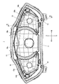
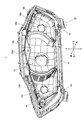
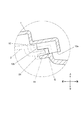
図1は、本実施形態における車両用灯具のハウジング(以下、単にハウジングという)1の正面図であり、図2は、ハウジング1の斜視図であり、図3は、図1のII−II線での断面図であり、図4は、図2のIII部を拡大した図であり、図5は、図3のIV部を拡大した図である。
FIG. 1 is a front view of a housing (hereinafter simply referred to as a housing) 1 of a vehicular lamp according to the present embodiment, FIG. 2 is a perspective view of the
図1〜図3に示すように、ハウジング1は、前面が開口した形状に形成され、その内部が左右方向に沿って3つのランプ室10,…に区分されている。各ランプ室10では、ハウジング1底面に穿設されたバルブ挿入孔10aが連通されており、このバルブ挿入孔10aの周囲のハウジング1底面が、当該バルブ挿入孔10aに挿入されるバルブ(図示せず)の光を反射させる反射面10bとなっている。
As shown in FIGS. 1 to 3, the
ハウジング1の前面開口の周縁には、前方に開口する断面コ字状の係合溝11が全周に亘って形成されている。この係合溝11は、内部にガスケットGが配置された状態で、ハウジング1の前面開口を覆うレンズ2の係合凸部21と係合される。そのため、係合溝11と係合凸部21とがガスケットGを挟みつつ係合されることにより、ハウジング1とレンズ2とで形成される灯室内がシールされる。
At the periphery of the front opening of the
係合溝11のうち、ハウジング1の下部の左右2箇所に位置する部分には、係合溝11の他の部分よりも後方へ深く且つ上側へ幅広に形成された拡大溝部12,12が設けられている。また、この拡大溝部12の下面のうち、係合溝11の他の部分よりも後方に位置する後端部分には、ハウジング1の外部と連通する連通孔12aが穿設されている。
Enlarged
そのため、図4及び図5に示すように、係合溝11の内部にガスケットGが配置されて当該ガスケットGを挟むようにレンズ2が係合溝11に係合された状態、つまり係合溝11がガスケットGで塞がれた状態であっても、拡大溝部12の上側部分及び後側部分と、連通孔12aとを通じて、灯室の内部が外部と連通される。これにより、ハウジング1とレンズ2とを車両用灯具として組み立てた状態において、拡大溝部12と連通孔12aとを通じて灯室内の水を灯室外へ排出することができる。
Therefore, as shown in FIGS. 4 and 5, the gasket G is disposed in the
以上のように、ハウジング1によれば、係合溝11の内部に配置されたガスケットGを挟むように当該係合溝11にレンズ2が係合された状態であっても、拡大溝部12の上側部分及び後側部分と連通孔12aとを通じて、ハウジング1及びレンズ2で形成される灯室の内部が外部と連通される。したがって、ガスケットの加工や位置合わせを必要とした従来に比べてガスケットGの組み込みを容易にしつつ、拡大溝部12と連通孔12aとを通じて灯室内の水を灯室外へ排出することができる。このようにガスケットGの組み込みが容易になることにより、組立時間や組立コストを低減させ、ひいてはメンテナンス性を改善することができる。
As described above, according to the
なお、本発明を適用可能な実施形態は、上述した実施形態に限定されることなく、本発明の趣旨を逸脱しない範囲で適宜変更可能である。 The embodiments to which the present invention can be applied are not limited to the above-described embodiments, and can be appropriately changed without departing from the spirit of the present invention.
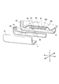
例えば、図6及び図7に示すように、拡大溝部12には、ガスケットGの当該拡大溝部12内への脱落を防止するためのリブ12bを設けてもよい。このリブ12bは、拡大溝部12のうち、係合溝11の他の部分よりも上側及び後側に位置する部分に、係合溝11の延在方向(略左右方向)に沿って拡大溝部12を仕切るように立設するのがよい。但し、当該リブ12bは、ガスケットGの脱落を防止することが可能であれば、拡大溝部12の上部及び/又は後部に部分的に設けることとしてもよい。このようなリブ12bを設けることにより、所望の排水性に応じて拡大溝部12を大きくした場合であっても、ガスケットGの脱落を防止することができる。
For example, as shown in FIGS. 6 and 7, the enlarged
1 ハウジング
11 係合溝
12 拡大溝部
12a 連通孔
12b リブ
2 レンズ
21 係合凸部
G ガスケット
DESCRIPTION OF
Claims (2)
前記係合溝のうち、当該ハウジングの下部に位置する部分には、当該係合溝の他の部分よりも後方へ深く且つ上側へ幅広に形成された拡大溝部が設けられ、
前記拡大溝部の下面のうち、前記係合溝の他の部分よりも後方に位置する後端部分には、当該ハウジングの外部と連通する連通孔が穿設されていることを特徴とする車両用灯具のハウジング。 In a vehicle lamp housing having a front surface formed in an opening shape and an engagement groove with which a lens covering the opening is engaged while sandwiching a gasket at the periphery of the opening,
Of the engaging groove, a portion located in the lower portion of the housing is provided with an enlarged groove portion formed deeper rearward and wider than the other portion of the engaging groove,
A communication hole that communicates with the outside of the housing is formed in a rear end portion located behind the other portion of the engagement groove in the lower surface of the enlarged groove portion. Light fixture housing.
Priority Applications (2)
| Application Number | Priority Date | Filing Date | Title |
|---|---|---|---|
| JP2011066877A JP2012204111A (en) | 2011-03-25 | 2011-03-25 | Housing of vehicular lamp |
| CN2012100741141A CN102692005A (en) | 2011-03-25 | 2012-03-20 | Shell of vehicle lamp |
Applications Claiming Priority (1)
| Application Number | Priority Date | Filing Date | Title |
|---|---|---|---|
| JP2011066877A JP2012204111A (en) | 2011-03-25 | 2011-03-25 | Housing of vehicular lamp |
Publications (1)
| Publication Number | Publication Date |
|---|---|
| JP2012204111A true JP2012204111A (en) | 2012-10-22 |
Family
ID=46857633
Family Applications (1)
| Application Number | Title | Priority Date | Filing Date |
|---|---|---|---|
| JP2011066877A Pending JP2012204111A (en) | 2011-03-25 | 2011-03-25 | Housing of vehicular lamp |
Country Status (2)
| Country | Link |
|---|---|
| JP (1) | JP2012204111A (en) |
| CN (1) | CN102692005A (en) |
Citations (3)
| Publication number | Priority date | Publication date | Assignee | Title |
|---|---|---|---|---|
| JPS6243402U (en) * | 1985-09-02 | 1987-03-16 | ||
| JPH01150307U (en) * | 1988-04-06 | 1989-10-18 | ||
| JPH11238406A (en) * | 1998-02-23 | 1999-08-31 | Honda Motor Co Ltd | Drainage passage structure for vehicular lighting |
Family Cites Families (2)
| Publication number | Priority date | Publication date | Assignee | Title |
|---|---|---|---|---|
| US4833572A (en) * | 1988-08-29 | 1989-05-23 | General Motors Corporation | Headlamp ventilation system |
| DE102004050744A1 (en) * | 2004-10-19 | 2006-05-24 | Hella Kgaa Hueck & Co. | Headlights for vehicles and manufacturing processes |
-
2011
- 2011-03-25 JP JP2011066877A patent/JP2012204111A/en active Pending
-
2012
- 2012-03-20 CN CN2012100741141A patent/CN102692005A/en active Pending
Patent Citations (3)
| Publication number | Priority date | Publication date | Assignee | Title |
|---|---|---|---|---|
| JPS6243402U (en) * | 1985-09-02 | 1987-03-16 | ||
| JPH01150307U (en) * | 1988-04-06 | 1989-10-18 | ||
| JPH11238406A (en) * | 1998-02-23 | 1999-08-31 | Honda Motor Co Ltd | Drainage passage structure for vehicular lighting |
Also Published As
| Publication number | Publication date |
|---|---|
| CN102692005A (en) | 2012-09-26 |
Similar Documents
| Publication | Publication Date | Title |
|---|---|---|
| JP2010052566A (en) | Vehicular lamp | |
| JP2006121880A (en) | Electrical junction box | |
| KR101626896B1 (en) | Pump for drainage and circulation | |
| JP6413335B2 (en) | Vehicle lighting | |
| JP2013050186A (en) | Mounting structure by clip | |
| EP2781825B1 (en) | Vehicle lighting unit | |
| JPH1131402A (en) | Vehicle lighting | |
| KR101786952B1 (en) | Camera with illumination sub assembly | |
| JP7161097B2 (en) | Lighting system and door trim | |
| CN102692005A (en) | Shell of vehicle lamp | |
| JP2010237473A (en) | Piezoelectric buzzer | |
| JP4597067B2 (en) | Vehicle lamp | |
| JP2018179264A (en) | Grommet | |
| JP3648426B2 (en) | Water drainage structure for vehicle lamps | |
| KR102262897B1 (en) | Cap for air breather | |
| EP3746704A1 (en) | Luminaire housing | |
| CN220171385U (en) | Shell and projector | |
| JP5956788B2 (en) | Vehicle lighting | |
| JP4701945B2 (en) | Electrical junction box positioning structure | |
| JP2560934Y2 (en) | Composite headlight shield plate | |
| JP4123434B2 (en) | Breather structure | |
| KR200148018Y1 (en) | Air vent devices for headlights for automobiles | |
| JP5669205B2 (en) | Anti-fogging structure for vehicular lamp | |
| KR200412956Y1 (en) | Lamp for the range hood | |
| JP2011060446A (en) | Vehicular lighting fixture |
Legal Events
| Date | Code | Title | Description |
|---|---|---|---|
| A621 | Written request for application examination |
Free format text: JAPANESE INTERMEDIATE CODE: A621 Effective date: 20140218 |
|
| A977 | Report on retrieval |
Free format text: JAPANESE INTERMEDIATE CODE: A971007 Effective date: 20141029 |
|
| A131 | Notification of reasons for refusal |
Free format text: JAPANESE INTERMEDIATE CODE: A131 Effective date: 20141104 |
|
| A02 | Decision of refusal |
Free format text: JAPANESE INTERMEDIATE CODE: A02 Effective date: 20150303 |