JP2012241981A - Solid fuel combustion device - Google Patents
Solid fuel combustion device Download PDFInfo
- Publication number
- JP2012241981A JP2012241981A JP2011112756A JP2011112756A JP2012241981A JP 2012241981 A JP2012241981 A JP 2012241981A JP 2011112756 A JP2011112756 A JP 2011112756A JP 2011112756 A JP2011112756 A JP 2011112756A JP 2012241981 A JP2012241981 A JP 2012241981A
- Authority
- JP
- Japan
- Prior art keywords
- fuel
- combustion
- supply
- combustion chamber
- furnace
- Prior art date
- Legal status (The legal status is an assumption and is not a legal conclusion. Google has not performed a legal analysis and makes no representation as to the accuracy of the status listed.)
- Withdrawn
Links
- 238000002485 combustion reaction Methods 0.000 title claims abstract description 159
- 239000004449 solid propellant Substances 0.000 title claims abstract description 29
- 239000000446 fuel Substances 0.000 claims abstract description 151
- 230000005484 gravity Effects 0.000 claims abstract description 18
- 238000007789 sealing Methods 0.000 claims abstract description 6
- 238000003780 insertion Methods 0.000 claims description 54
- 230000037431 insertion Effects 0.000 claims description 54
- 239000000567 combustion gas Substances 0.000 claims description 7
- 238000010438 heat treatment Methods 0.000 claims description 5
- 238000007599 discharging Methods 0.000 claims description 3
- 239000002023 wood Substances 0.000 abstract description 51
- 239000008188 pellet Substances 0.000 abstract description 12
- 239000000463 material Substances 0.000 abstract description 5
- 230000000694 effects Effects 0.000 description 5
- 230000002093 peripheral effect Effects 0.000 description 5
- 239000002028 Biomass Substances 0.000 description 3
- 239000004071 soot Substances 0.000 description 3
- 239000007789 gas Substances 0.000 description 2
- 230000014509 gene expression Effects 0.000 description 2
- 239000002184 metal Substances 0.000 description 2
- 238000000034 method Methods 0.000 description 2
- 238000005192 partition Methods 0.000 description 2
- 230000000903 blocking effect Effects 0.000 description 1
- 238000005266 casting Methods 0.000 description 1
- 239000003245 coal Substances 0.000 description 1
- 230000007423 decrease Effects 0.000 description 1
- 238000010586 diagram Methods 0.000 description 1
- 230000006698 induction Effects 0.000 description 1
- 238000009434 installation Methods 0.000 description 1
- 238000012986 modification Methods 0.000 description 1
- 230000004048 modification Effects 0.000 description 1
- 238000012856 packing Methods 0.000 description 1
- 230000002265 prevention Effects 0.000 description 1
- 238000007790 scraping Methods 0.000 description 1
- 238000000638 solvent extraction Methods 0.000 description 1
- 239000003381 stabilizer Substances 0.000 description 1
- 230000000087 stabilizing effect Effects 0.000 description 1
- 238000010792 warming Methods 0.000 description 1
Images
Landscapes
- Solid-Fuel Combustion (AREA)
- Air Supply (AREA)
Abstract
Description
本発明は、塊状燃料の供給に重力又は自然落下を利用する燃焼装置に係り、更に詳しくは、木質チップ、木質ペレット等の塊状燃料が積み重なっていても積み重なった塊状燃料の間に効果的に燃焼空気を供給できるようにし、また、塊状燃料の形状にあわせて火格子装置を取り替えできるようにした燃焼装置に関する。 The present invention relates to a combustion apparatus that uses gravity or natural fall for supplying bulk fuel, and more particularly, even when bulk fuel such as wood chips and wood pellets is stacked, it is effectively burned between the stacked bulk fuels. The present invention relates to a combustion apparatus in which air can be supplied and a grate apparatus can be replaced in accordance with the shape of the bulk fuel.
地球温暖化防止に寄与し、また、自給可能なエネルギーとして、林地残材、間伐材、枝条、製材端材などの木質材料から取り出す木質バイオマスエネルギーが着目されている。
木質バイオマスエネルギーとしては、木質チップや木質ペレット等がある。
As biomass that contributes to the prevention of global warming and can be self-sufficient, wood biomass energy extracted from woody materials such as forest residue, thinned wood, branches and sawn timber is drawing attention.
Woody biomass energy includes wood chips and wood pellets.
主として木質ペレットの供給に重力又は自然落下を利用する固形燃料ストーブが下記の特許文献1に開示されている。特許文献1記載の固形燃料ストーブは、固形燃料として木質ペレット、木材チップ或いは石炭を使用し、固形燃料の供給及び燃焼に電力を使用しないで電力供給に制限のある場所への固形燃料ストーブの設置を可能とするものである。
そして前記固形燃料ストーブは、燃焼室内に固形燃料を供給する量の調整ができる燃料調整機構を有している。
The solid fuel stove has a fuel adjustment mechanism capable of adjusting the amount of solid fuel supplied into the combustion chamber.
特許文献1には、ストーブの固形燃料として木質チップもあげられている。しかし、木材チップは木質ペレットと異なり形状の均一性に欠けるために流動性が低く、このため前記燃料調整機構が供給路中に装備されていると、供給阻害要素となって木材チップが供給されない可能性がある。
また、特許文献1記載の固形燃料ストーブは、火格子が下方に向けて突き出た湾曲状となって、いわば容器の形状を呈しているために、火格子中央部分には固形燃料が山積みになり易く、山積みになった固形燃料の内部では燃焼空気が不足し、燃焼継続が困難となる課題がある。
Moreover, since the solid fuel stove described in
(本発明の目的)
そこで本発明の目的は、塊状燃料の供給に重力又は自然落下を利用する固体燃料燃焼装置において、木質ペレットの他に、林地残材、間伐材、枝条、製材端材などの木質材料を破砕して製造する木質チップの供給を可能にすることにある。
また、本発明の他の目的は、塊状燃料が積み重なっていても効果的に燃焼空気を供給できるようにすることにある。
更に、本発明の他の目的は、塊状燃料の形状にあわせて火格子装置を取り替えできるようにすることにある。
(Object of the present invention)
Therefore, an object of the present invention is to crush wooden materials such as forest land residual materials, thinned wood, branches, and sawn timber, in addition to wood pellets, in a solid fuel combustion apparatus that uses gravity or natural fall for supplying bulk fuel. It is to enable supply of wood chips to be manufactured.
Another object of the present invention is to make it possible to supply combustion air effectively even when bulk fuel is stacked.
Furthermore, another object of the present invention is to make it possible to replace the grate apparatus in accordance with the shape of the bulk fuel.
上記課題を解決するために本発明が講じた手段は次のとおりである。
燃焼炉と、該燃焼炉の燃焼室に、重力によって塊状燃料を供給する燃料供給装置と、前記燃焼炉の燃焼室に設置される火格子装置と、前記燃焼室で発生した燃焼ガスを排出する煙突又は煙道と、を有する燃焼装置であって、
前記燃焼炉の炉壁は、
前記燃料供給装置の供給部を挿入する挿入口と、前記燃焼室に設置される火格子装置を搬入又は搬出する、扉を備えた出入口と、を有し、
前記燃料供給装置は、
塊状燃料を貯留する貯留部と、該貯留部の燃料搬入口を密閉する閉塞扉と、
前記貯留部の下に連設されており、前記燃焼炉の挿入口に挿入して燃焼室に塊状燃料を供給する供給部と、を有し、
前記火格子装置は、
燃料支持床と、該燃料支持床を支持する支脚と、前記燃料支持床に立設されており、筒壁に適宜数の空気供給孔が設けられている適宜数の空気供給筒と、を有し、
前記火格子装置は、前記燃焼炉内に搬入又は搬出可能であり、前記燃料供給装置の供給部を挿入する挿入口は供給部の外形よりも大きく形成され、挿入した供給部と前記挿入口の間には、空気誘引部が形成される、
固体燃料燃焼装置である。
Means taken by the present invention to solve the above problems are as follows.
A combustion furnace, a fuel supply device for supplying bulk fuel to the combustion chamber of the combustion furnace by gravity, a grate device installed in the combustion chamber of the combustion furnace, and a combustion gas generated in the combustion chamber A combustion device having a chimney or a flue,
The furnace wall of the combustion furnace is
An insertion port for inserting a supply part of the fuel supply device, and an entrance / exit with a door for carrying in or out a grate device installed in the combustion chamber,
The fuel supply device includes:
A storage section for storing bulk fuel, a closing door for sealing the fuel inlet of the storage section,
A supply section that is provided below the storage section and that is inserted into the insertion port of the combustion furnace and supplies a bulk fuel to the combustion chamber;
The grate device is
A fuel support floor, a supporting leg that supports the fuel support floor, and an appropriate number of air supply cylinders that are erected on the fuel support floor and in which an appropriate number of air supply holes are provided in the cylinder wall. And
The grate device can be carried into or out of the combustion furnace, and the insertion port for inserting the supply unit of the fuel supply device is formed larger than the outer shape of the supply unit, and the inserted supply unit and the insertion port In between, an air attracting part is formed,
Solid fuel combustion device.
本発明は、
燃焼炉と、該燃焼炉の燃焼室に、重力によって塊状燃料を供給する燃料供給装置と、前記燃焼炉の燃焼室に設置される火格子装置と、前記燃焼室で発生した燃焼ガスを排出する煙突又は煙道と、を有する燃焼装置であって、
前記燃焼炉の炉壁は、
前記燃料供給装置の供給部を挿入する第1の挿入口及び第2の挿入口と、前記燃焼室に設置される火格子装置を搬入又は搬出する、扉を備えた出入口と、を有し、
前記燃料供給装置は、
塊状燃料を貯留する貯留部と、該貯留部の燃料搬入口を密閉する閉塞扉と、前記貯留部の下に連設されており、前記燃焼炉の第1の挿入口又は第2の挿入口に挿入して燃焼室に塊状燃料を供給する供給部と、を有し、
前記火格子装置は、
燃料支持床と、該燃料支持床を支持する支脚と、前記燃料支持床に立設されており、筒壁に適宜数の空気供給孔が設けられている適宜数の空気供給筒と、を有し、
前記火格子装置は、前記燃焼炉内に搬入又は搬出可能であり、前記燃料供給装置の供給部を挿入する第1の挿入口及び第2の挿入口は供給部の外形よりも大きく形成され、挿入した供給部と前記挿入口の間には、空気誘引部が形成される、
固体燃料燃焼装置である。
The present invention
A combustion furnace, a fuel supply device for supplying bulk fuel to the combustion chamber of the combustion furnace by gravity, a grate device installed in the combustion chamber of the combustion furnace, and a combustion gas generated in the combustion chamber A combustion device having a chimney or a flue,
The furnace wall of the combustion furnace is
A first insertion port and a second insertion port for inserting the supply part of the fuel supply device, and an inlet / outlet with a door for carrying in or out a grate device installed in the combustion chamber,
The fuel supply device includes:
A storage section for storing bulk fuel, a closing door for sealing a fuel carry-in port of the storage section, and a first insertion port or a second insertion port of the combustion furnace, which are continuously provided below the storage unit. And a supply part for supplying the bulk fuel to the combustion chamber.
The grate device is
A fuel support floor, a supporting leg that supports the fuel support floor, and an appropriate number of air supply cylinders that are erected on the fuel support floor and in which an appropriate number of air supply holes are provided in the cylinder wall. And
The grate device can be carried into or out of the combustion furnace, and the first insertion port and the second insertion port for inserting the supply unit of the fuel supply device are formed larger than the outer shape of the supply unit, An air attracting part is formed between the inserted supply part and the insertion port.
Solid fuel combustion device.
前記固体燃料燃焼装置の燃料支持床として傾斜床又は水平床を有し、これらは択一的に使用されるのが好ましい。 The solid fuel combustion apparatus has an inclined bed or a horizontal bed as a fuel support bed, and these are preferably used alternatively.
前記固体燃料燃焼装置の燃焼炉の炉壁は、第1の扉を備えた第1の出入口に加えて、前記燃焼炉内に区画されている加熱室に物を搬入又は搬出する、第2の扉を備えた第2の出入口と、を有するのが好ましい。 The furnace wall of the combustion furnace of the solid fuel combustion apparatus is configured to carry in or out an object in a heating chamber defined in the combustion furnace, in addition to a first door provided with a first door. And a second doorway with a door.
特許請求の範囲及び明細書において、「密閉」の用語は、厳密な意味での気密性を含むほか、貯留部内に燃焼空気が入り、貯留部又は供給部内で貯留又は待機中の塊状燃料が燃焼するのを妨げる程度の気密性を確保できる場合も含むものとして使用している。 In the claims and the specification, the term “sealing” includes airtightness in a strict sense, combustion air enters the storage section, and bulk fuel that is stored or waiting in the storage section or supply section burns. It is used as including the case where the airtightness to the extent of hindering it can be secured.
(作用)
本発明に係る固体燃料燃焼装置の作用を説明する。
燃焼炉の扉を開けて燃焼室内に火格子装置を搬入し、燃焼室内に設置する。
(Function)
The operation of the solid fuel combustion apparatus according to the present invention will be described.
Open the door of the combustion furnace, carry the grate device into the combustion chamber, and install it in the combustion chamber.
燃料供給装置は、供給部の先端部を挿入口に挿入する。燃焼炉に燃料供給装置を装備した後、貯留部内に塊状燃料を搬入し、燃料搬入口を閉塞扉で閉じて、燃料搬入口から貯留部内に空気が入らないようにする。 The fuel supply device inserts the distal end portion of the supply portion into the insertion port. After the combustion furnace is equipped with the fuel supply device, the bulk fuel is carried into the reservoir, and the fuel inlet is closed with a closed door so that air does not enter the reservoir from the fuel inlet.
貯留部内の塊状燃料は重力で下方に流動し、燃焼室内に入る。燃焼室内に入った塊状燃料に適宜方法で着火し、塊状燃料を燃焼する。塊状燃料が燃え尽きると灰になって燃料支持床の貫通孔から落下し、それに伴って燃焼室内の塊状燃料の嵩が減ると重力によって順次貯留部側から塊状燃料が供給される。 The bulk fuel in the reservoir flows downward due to gravity and enters the combustion chamber. The bulk fuel entering the combustion chamber is ignited by an appropriate method, and the bulk fuel is burned. When the bulk fuel burns out, it becomes ash and falls from the through hole of the fuel support floor, and when the bulk of the bulk fuel in the combustion chamber decreases, the bulk fuel is sequentially supplied from the storage portion side by gravity.
塊状燃料の燃焼によって生じた燃焼ガスは煙突から排出され、排出される際の煙突効果によって、燃焼室内の圧力が低下するため、空気誘引部から空気が所要の流速で誘引される。このため塊状燃料の燃焼によって生じている火炎は、供給部先端の供給口から遠ざかる方向になびき動く。また、低温の外気によって雰囲気も冷却される。これらの作用によって供給部で待機中の塊状燃料が燃焼するのを防止する。 The combustion gas generated by the combustion of the bulk fuel is discharged from the chimney, and the pressure in the combustion chamber is lowered due to the chimney effect when being discharged, so that air is attracted from the air attracting portion at a required flow rate. For this reason, the flame generated by the combustion of the bulk fuel moves in a direction away from the supply port at the tip of the supply unit. In addition, the atmosphere is cooled by the low-temperature outside air. These actions prevent burning of the bulk fuel waiting in the supply section.
なお、燃焼室内で燃焼中の塊状燃料から貯留部内で供給待機中の塊状燃料までは、重力により供給されるべく連続しており、燃焼室側近傍の塊状燃料から貯留部内の塊状燃料に向かって延焼する可能性が無いわけではない。
しかし、貯留部内は、扉が閉じられて気密状態にあることから燃焼空気が不足し、燃焼室側近傍の塊状燃料から延焼することを防止している。
Note that the bulk fuel that is burning in the combustion chamber to the bulk fuel that is waiting to be supplied in the reservoir is continuous to be supplied by gravity, and from the bulk fuel in the vicinity of the combustion chamber toward the bulk fuel in the reservoir. It is not without the possibility of spreading fire.
However, since the door is closed and is in an airtight state, the storage portion is short of combustion air and prevents the spread of fuel from the bulk fuel near the combustion chamber.
貯留部とは異なり、第1の出入口と第1の扉との間は密閉状態ではないので、前記煙突効果の作用により、第1の出入口と第1扉との隙間から燃焼空気が燃焼室内に誘引される。
第1の出入口と第1の扉間の隙間から誘引された燃焼空気の一部は、燃料支持床下の空間を通り、燃料支持床の貫通孔から、また、空気供給筒内を通って筒壁の空気供給孔から、それぞれ燃焼室内に供給される。
Unlike the reservoir, the first entrance and the first door are not sealed, so that the combustion air is introduced into the combustion chamber from the gap between the first entrance and the first door by the action of the chimney effect. Attracted.
Part of the combustion air attracted from the gap between the first doorway and the first door passes through the space below the fuel support floor, passes through the through hole of the fuel support floor, and passes through the air supply cylinder to the cylinder wall. The air supply holes are supplied to the combustion chamber.
空気供給筒の周囲に集積された塊状燃料の中に埋もれている空気供給孔からは、集積された塊状燃料の中に燃焼空気が送られ(好ましくは放射状に)、塊状燃料を効率よく燃焼する。
空気供給孔のうち塊状燃料の上側に露出しているものは、空気供給孔から噴き出している空気と塊状燃料が可燃ガス化したガスが混合し、塊状燃料は効率良く燃焼する。
From the air supply hole buried in the bulk fuel accumulated around the air supply cylinder, combustion air is sent into the accumulated bulk fuel (preferably radially), and the bulk fuel is burned efficiently. .
Of the air supply holes, those exposed above the bulk fuel are mixed with the air ejected from the air supply holes and the gas in which the bulk fuel is combusted, and the bulk fuel burns efficiently.
本発明によれば、塊状燃料として木質ペレットの他、木質チップも重力又は自然落下を利用して供給可能である。
また、塊状燃料が積み重なっていても効果的に燃焼空気を供給できる。
According to the present invention, wooden chips as well as wooden pellets can be supplied as a bulk fuel using gravity or natural fall.
Moreover, even if the bulk fuel is stacked, the combustion air can be supplied effectively.
更に、塊状燃料の特性に合わせた少なくとも二種類の火格子装置を有するものは、塊状燃料の特性に合った燃料支持床を選択できるため、塊状燃料の形状に制限を受けない又は受けにくくなる燃焼装置が提供できる。 Further, those having at least two types of grate devices that match the characteristics of the bulk fuel can select a fuel support bed that matches the characteristics of the bulk fuel, so that combustion that is not limited or difficult to receive by the shape of the bulk fuel A device can be provided.
なお、塊状燃料が集積されると、集積された塊状燃料の内部は燃焼空気が不足した状態となる。しかし、火格子装置の燃料支持床に空気供給筒が立設されているので、燃焼空気は空気供給筒から塊状燃料に供給され、ブロワーなどを使用しなくても燃焼効率の向上を図ることができる。したがって、災害地のように電力が供給されない場合の燃焼装置や暖房器具として好適である。 When the bulk fuel is accumulated, the accumulated bulk fuel is in a state where the combustion air is insufficient. However, since the air supply cylinder is erected on the fuel support floor of the grate device, the combustion air is supplied to the bulk fuel from the air supply cylinder, and the combustion efficiency can be improved without using a blower or the like. it can. Therefore, it is suitable as a combustion device or a heating appliance when power is not supplied as in a disaster area.
本発明を図に示した実施の形態に基づき詳細に説明する。
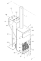
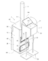
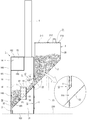
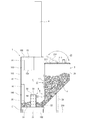
図1から図3に示すように、固体燃料燃焼装置は、燃焼炉1と、燃焼炉1の燃焼室11に重力によって塊状燃料Fを供給する燃料供給装置2と、燃焼室11内に設置される火格子装置3と、燃焼室11で発生した燃焼ガスを排出する煙突4又は煙道を有する。
The present invention will be described in detail based on the embodiments shown in the drawings.
As shown in FIGS. 1 to 3, the solid fuel combustion apparatus is installed in the
燃焼炉1は、例えば金属板や鋳造によって構築され、炉壁10と炉壁10で囲まれる燃焼室11を有する。炉壁10は、周壁101,天壁102,底壁103で構成される。
The
周壁101の背面側(図2,3,5では右側)には、後で説明する燃料供給装置2の供給部22を挿入する第1の挿入口12及び第2の挿入口13を有する。第1の挿入口12と第2の挿入口13は、何れか一方が使用されるものであり、使用されない他方の挿入口は、摺動する挿入口閉鎖扉17で閉じられる。挿入口閉鎖扉17は、第1の挿入口12及び第2の挿入口13の口縁の上下に設けられた案内により案内されて摺動する。
On the back side of the peripheral wall 101 (on the right side in FIGS. 2, 3, and 5), there are a
周壁101の正面側(図1では右側)の下方には、第1の出入口14を有する。第1の出入口14は、燃焼室11内に設置される火格子装置3の搬入、搬出、灰の掻きだし、又は薪を燃やすときに開閉される。第1の出入口14は第1の扉140を備える。
また、上方には、第2の出入口16を有する。第2の出入口16は、燃焼室11内を区画板150で区画して形成されている加熱室15に物を搬入・搬出するときに使用される。第2の出入口16は第2の扉160を備える。
A
In addition, a
燃料供給装置2は、塊状燃料Fを貯留する貯留部であるホッパ20を有する。
ホッパ20上面の略半分が閉塞板211で閉塞されており、残りの略半分は燃料搬入口21となっている。燃料搬入口21の縁部には、閉塞板211との間にヒンジ部212を介して閉塞扉210が取り付けられている。
The
About half of the upper surface of the
閉塞扉210は、例えば周縁にゴムパッキンを配し、燃料搬入口21の口縁と協働して燃料搬入口21を密閉できるように構成されており、ホッパ20内に燃焼空気が入るのを妨げてホッパ内部を気密状態とする。これにより、後で説明するように、ホッパ内の塊状燃料が燃焼室内で燃焼している塊状燃料からの延焼によって燃焼するのを防止する。
The closing
ホッパ20の下側には、燃焼炉1の第1の挿入口12又は第2の挿入口13に挿入して燃焼室11内に塊状燃料Fを供給する供給部22が連設されている。本実施の形態においては、供給部22は筒状に形成され、先端には供給口220を有する。
ホッパ20の対向する両側壁には、ホッパ20及び供給部22の高さを調整する支脚23,23を有する。支脚23,23は、径を異にする管体を入れ子式にした構造で、下端に安定板230,230を備えている。支脚23,23は、高さを調整した後に、例えば固定ピンなどで一定の高さを保持できるようになっている。支脚23,23の構造としては、公知の各種構造が採用できる。
A
Supporting
燃焼炉1の燃焼室11内には火格子装置3が設置される。
火格子装置3は、塊状燃料Fの落下を防止する燃料支持床30を有する。燃料支持床30は、多数の貫通孔301を有する。貫通孔301は、塊状燃料Fの燃焼後の灰を落下させ、また、燃焼空気を燃料支持床30の下側から燃焼室11内に取り入れる。
燃料支持床30の両側縁には、燃料支持床30を支持する支脚31,31を備える。本実施の形態では、燃料支持床30には、エキスパンドメタルを使用している。また、支脚31,31は板状となっているが、支柱状でも良い。
火格子装置3は、燃焼炉1とは別体となっており、燃焼炉1内に搬入し、また、燃焼炉1内から搬出可能となっている。
A
The
Supporting
The
燃料支持床30の略中央部には、空気供給筒5が立設されている。空気供給筒5は下端が開口され、上端は閉塞板52で閉塞されている。空気供給筒5の筒壁50には、全周面に亘って適宜数の空気供給孔51が設けられている。
空気供給筒5は、燃焼室11の空間部の大きさ、空気供給筒5の外径等の設置条件を加味して適宜数設置される。
An
An appropriate number of
前記した燃料供給装置2の供給部22を挿入する第1の挿入口12及び第2の挿入口13は、供給部22の外形よりも大きく形成されており、挿入した供給部22外周面と前記挿入口12,13の口縁の間で形成された隙間により、空気誘引部6が形成される。
空気誘引部6の面積(隙間部分の面積)は、供給部22の外形と挿入口12,13の口径によって決まる。また、空気誘引部6の面積が広いと誘引される空気の流速は遅くなり、空気誘引部6の面積が狭いと誘引される空気の流速は速くなる。
The
The area of the air attraction unit 6 (the area of the gap) is determined by the outer shape of the
空気誘引部6の形状は供給部22と挿入口12,13間の位置関係によって決まり、供給部22の外周面が挿入口12,13の縁部の何れの箇所にも接しないときには、「ロ」枠状に形成される。供給部22の外周面と挿入口12,13の縁部との接触の仕方によって「L」や「コ」状ともなる。
The shape of the
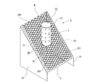
火格子装置3は、燃料支持床30の床面の状態による少なくとも二種類を有する。一つは木質チップ用に使用する、床面が傾斜している傾斜床32であり、他の一つは木質ペレット用に使用する、床面が水平状態の水平床33である。水平床33は、薪を燃焼する場合にも使用する。
傾斜床32は、水平床33に比べて面積が広く、燃料支持床30から燃焼室11内に流入する燃焼空気の量が多くなる効果がある。
The
The
木質チップは、形状が一定しておらず流動性に欠けるために燃料支持床30の全面に散在できるように傾斜床32が選択される。燃料供給装置2から供給された流動性に欠ける木質チップは傾斜床32の上を滑り又は転がり落ち、傾斜床32の全体に散在できるようになる。
Since the wood chips are not uniform in shape and lack fluidity, the
木質ペレットは,工業的に製造されるために基本的には形状が一定であり、木質チップに比べて流動性に富み、形状も転がりやすいので、水平床33が選択される。燃料供給装置2から供給された木質ペレットは、水平床33の床面を転がって全体に散在する。
このように火格子装置3は、供給される燃料によって択一的に使用されるものである。
なお、燃料として燃焼室11に直接薪を入れて燃やす場合もあるが、その場合は、水平床33が使用される。
Since the wood pellets are manufactured industrially, the shape is basically constant, the fluidity is higher than that of the wood chips, and the shape is easy to roll, so the horizontal floor 33 is selected. The wood pellets supplied from the
As described above, the
In some cases, soot is burned directly into the
(作用)
本実施の形態の作用を説明する。
塊状燃料Fの違いによって、火格子装置3の燃料支持床30が選択され、それによって燃料供給装置2の高さを変える。
(Function)
The operation of the present embodiment will be described.
The
まず、塊状燃料Fが木質チップの場合を説明する。
木質チップの場合は、火格子装置3として、傾斜床32を有するものを選択する。燃焼炉1の第1の扉140を開けて燃焼室11内に火格子装置3を搬入し、高端側Hを第1の挿入口12側に、低端側Lを第1の出入口14側にして燃焼室内11内に設置する。
First, the case where the bulk fuel F is a wood chip will be described.
In the case of a wood chip, a
燃料供給装置2は、供給部22の先端部の高さが第1の挿入口12に挿入できる高さになるよう支脚23,23の長さを設定し、供給部22の先端部を第1の挿入口12に挿入する。燃焼炉1に燃料供給装置2を装備した後、ホッパ20内に木質チップを搬入し、燃料搬入口21を閉塞扉210で閉じて、燃料搬入口21からホッパ20内に空気が入らないようにする。第2の挿入口13は、挿入口閉鎖扉17で閉じておく。
The
ホッパ20内の木質チップは重力で下方に流動し、燃焼室11内に入る。燃焼室11内に入った木質チップに適宜方法で着火し、木質チップを燃焼する。木質チップが燃え尽きると灰になって燃料支持床30の貫通孔301から落下し、それに伴って燃焼室11内の木質チップの嵩が減ると重力によって順次ホッパ20側から木質チップが供給される。
The wood chip in the
木質チップの燃焼によって生じた燃焼ガスは煙突4から排出され、排出される際の煙突効果によって、燃焼室11内の圧力が低下するため、空気誘引部6から空気が所要の流速を持って誘引される。このため木質チップの燃焼によって生じている火炎は、供給部22先端の供給口220から遠ざかる方向になびき動く。また、低温の外気によって雰囲気も冷却される。これらの作用によって供給部22で待機中の木質チップが燃焼するのを防止する。
The combustion gas generated by the combustion of the wood chip is discharged from the
なお、燃焼室11内で燃焼中の木質チップからホッパ20内で待機中の木質チップまでは、重力により供給されるべく連続しており、燃焼室11側近傍の木質チップからホッパ20内の木質チップに向かって延焼しようとする。
しかし、ホッパ20内は、閉塞扉210が閉じられて気密状態にあることから燃焼空気が不足し、燃焼室11側近傍の木質チップからの延焼を防止する。
Note that the wood chips burning in the
However, since the
第1の出入口14と第1の扉140との間は密閉状態ではないので、前記煙突効果の作用により、第1の出入口14と第1の扉140との隙間から燃焼空気が燃焼室11内に誘引される。第1の出入口14と第1の扉140間の隙間から誘引された燃焼空気の一部は、燃料支持床30と底壁103との間の空間を通り、燃料支持床30の貫通孔301から燃焼室11内に供給される。また、空気供給筒5内を通って筒壁50の空気供給孔51から燃焼室11内に供給される。
Since the space between the
空気供給筒5の周囲には木質チップが集積されており、木質チップの中に埋もれている空気供給孔51からは集積された木質チップの中に放射状に燃焼空気が送られ、木質チップは効率よく燃焼する。
空気供給孔51のうち木質チップの上側に露出しているものは、空気供給孔51から噴き出している空気と木質チップが可燃ガス化したガスが混合し、木質チップを効率良く燃焼させる。
Wood chips are accumulated around the
Of the air supply holes 51 that are exposed above the wood chips, the air blown out from the air supply holes 51 and the gas generated by combusting the wood chips are mixed to efficiently burn the wood chips.
次に、塊状燃料Fが木質ペレットの場合を説明する。
火格子装置3として、水平床33を有するものを選択し、第1の扉140を開けて燃焼室11内に搬入して燃焼室内11内に設置する。
Next, a case where the bulk fuel F is a wood pellet will be described.
A
燃料供給装置2は、供給部22の先端部の高さが第2の挿入口13に挿入できる高さに支脚23,23の高さを調整し、供給部22を第2の挿入口13に挿入する。このとき、第1の挿入孔12は、挿入口閉鎖扉17で閉じておく。
着火後の状況は、木質チップの場合と大体同じであるから、前記説明を援用する。
The
Since the situation after ignition is almost the same as in the case of wood chips, the above explanation is used.
なお、本明細書で使用している用語と表現は、あくまでも説明上のものであって、なんら限定的なものではなく、本明細書に記述された特徴およびその一部と等価の用語や表現を除外する意図はない。また、本発明の技術思想の範囲内で、種々の変形態様が可能であるということは言うまでもない。 Note that the terms and expressions used in this specification are merely explanatory and are not limiting at all, and terms and expressions equivalent to the features described in this specification and parts thereof. There is no intention to exclude. It goes without saying that various modifications are possible within the scope of the technical idea of the present invention.
F 塊状燃料
1 燃焼炉
10 炉壁
101 周壁
102 天壁
103 底壁
11 燃焼室
12 第1の挿入口
13 第2の挿入口
14 第1の出入り口
140 第1の扉
15 加熱室
150 区画板
16 第2の出入り口
160 第2の扉
17 挿入口閉鎖扉
2 燃料供給装置
20 ホッパ
21 燃料搬入口
210 閉塞扉
211 閉塞板
212 ヒンジ部
22 供給部
220 供給口
23 支脚
230 安定板
3 火格子装置
30 燃料支持床
301 貫通孔
31 支脚
32 傾斜床
33 水平床
4 煙突
5 空気供給筒
50 筒壁
51 空気供給孔
52 閉塞板
6 空気誘引部
H 高端側
L 低端側
Claims (4)
該燃焼炉(1)の燃焼室(11)に、重力によって塊状燃料(F)を供給する燃料供給装置(2)と、
前記燃焼炉(1)の燃焼室(11)に設置される火格子装置(3)と、
前記燃焼室(11)で発生した燃焼ガスを排出する煙突(4)又は煙道と、を有する燃焼装置であって、
前記燃焼炉(1)の炉壁(10)は、
前記燃料供給装置(2)の供給部(22)を挿入する挿入口(12,13)と、
前記燃焼室(11)に設置される火格子装置(3)を搬入又は搬出する、扉(140)を備えた出入口(14)と、
を有し、
前記燃料供給装置(2)は、
塊状燃料を貯留する貯留部(20)と、
該貯留部(20)の燃料搬入口(21)を密閉する閉塞扉(210)と、
前記貯留部(20)の下に連設されており、前記燃焼炉(1)の挿入口(12,13)に挿入して燃焼室(11)に塊状燃料を供給する供給部(22)と、
を有し、
前記火格子装置(3)は、
燃料支持床(30)と、
該燃料支持床(30)を支持する支脚(31)と、
前記燃料支持床(30)に立設されており、筒壁(50)に適宜数の空気供給孔(51)が設けられている適宜数の空気供給筒(5)と、
を有し、
前記火格子装置(3)は、前記燃焼炉(1)内に搬入又は搬出可能であり、
前記燃料供給装置(2)の供給部(22)を挿入する挿入口(12,13)は供給部(22)の外形よりも大きく形成され、挿入した供給部(22)と前記挿入口(12,13)の間には、空気誘引部(6)が形成される、
固体燃料燃焼装置。 A combustion furnace (1),
A fuel supply device (2) for supplying bulk fuel (F) by gravity to the combustion chamber (11) of the combustion furnace (1);
A grate device (3) installed in the combustion chamber (11) of the combustion furnace (1);
A combustion device having a chimney (4) or a flue for discharging combustion gas generated in the combustion chamber (11),
The furnace wall (10) of the combustion furnace (1),
Insertion ports (12, 13) for inserting the supply section (22) of the fuel supply device (2);
An entrance / exit (14) having a door (140) for carrying in or out a grate device (3) installed in the combustion chamber (11);
Have
The fuel supply device (2)
A reservoir (20) for storing bulk fuel; and
A closing door (210) for sealing the fuel inlet (21) of the reservoir (20);
A supply unit (22) that is provided below the storage unit (20), and that is inserted into the insertion ports (12, 13) of the combustion furnace (1) and supplies the bulk fuel to the combustion chamber (11); ,
Have
The grate device (3)
A fuel support floor (30);
A support leg (31) for supporting the fuel support floor (30);
An appropriate number of air supply cylinders (5) which are erected on the fuel support floor (30) and have an appropriate number of air supply holes (51) provided in the cylinder wall (50);
Have
The grate device (3) can be carried into or out of the combustion furnace (1),
The insertion ports (12, 13) for inserting the supply portion (22) of the fuel supply device (2) are formed larger than the outer shape of the supply portion (22), and the inserted supply portion (22) and the insertion port (12) , 13), an air attracting part (6) is formed,
Solid fuel combustion device.
該燃焼炉(1)の燃焼室(11)に、重力によって塊状燃料(F)を供給する燃料供給装置(2)と、
前記燃焼炉(1)の燃焼室(11)に設置される火格子装置(3)と、
前記燃焼室(11)で発生した燃焼ガスを排出する煙突(4)又は煙道と、を有する燃焼装置であって、
前記燃焼炉(1)の炉壁(10)は、
前記燃料供給装置(2)の供給部(22)を挿入する第1の挿入口(12)及び第2の挿入口(13)と、
前記燃焼室(11)に設置される火格子装置(3)を搬入又は搬出する、扉(140)を備えた出入口(14)と、
を有し、
前記燃料供給装置(2)は、
塊状燃料を貯留する貯留部(20)と、
該貯留部(20)の燃料搬入口(21)を密閉する閉塞扉(210)と、
前記貯留部(20)の下に連設されており、前記燃焼炉(1)の第1の挿入口(12)又は第2の挿入口(13)に挿入して燃焼室(11)に塊状燃料を供給する供給部(22)と、
を有し、
前記火格子装置(3)は、
燃料支持床(30)と、
該燃料支持床(30)を支持する支脚(31)と、
前記燃料支持床(30)に立設されており、筒壁(50)に適宜数の空気供給孔(51)が設けられている適宜数の空気供給筒(5)と、
を有し、
前記火格子装置(3)は、前記燃焼炉(1)内に搬入又は搬出可能であり、
前記燃料供給装置(2)の供給部(22)を挿入する第1の挿入口(12)及び第2の挿入口(13)は供給部(22)の外形よりも大きく形成され、挿入した供給部(22)と前記第1の挿入口(12)及び第2の挿入口(13)の間には、空気誘引部(6)が形成される、
固体燃料燃焼装置。 A combustion furnace (1),
A fuel supply device (2) for supplying bulk fuel (F) by gravity to the combustion chamber (11) of the combustion furnace (1);
A grate device (3) installed in the combustion chamber (11) of the combustion furnace (1);
A combustion device having a chimney (4) or a flue for discharging combustion gas generated in the combustion chamber (11),
The furnace wall (10) of the combustion furnace (1),
A first insertion port (12) and a second insertion port (13) for inserting the supply section (22) of the fuel supply device (2);
An entrance / exit (14) having a door (140) for carrying in or out a grate device (3) installed in the combustion chamber (11);
Have
The fuel supply device (2)
A reservoir (20) for storing bulk fuel; and
A closing door (210) for sealing the fuel inlet (21) of the reservoir (20);
It is continuously provided under the storage part (20), and is inserted into the first insertion port (12) or the second insertion port (13) of the combustion furnace (1) to form a lump in the combustion chamber (11). A supply section (22) for supplying fuel;
Have
The grate device (3)
A fuel support floor (30);
A support leg (31) for supporting the fuel support floor (30);
An appropriate number of air supply cylinders (5) which are erected on the fuel support floor (30) and have an appropriate number of air supply holes (51) provided in the cylinder wall (50);
Have
The grate device (3) can be carried into or out of the combustion furnace (1),
The first insertion port (12) and the second insertion port (13) into which the supply unit (22) of the fuel supply device (2) is inserted are formed larger than the outer shape of the supply unit (22) and are inserted. An air attraction part (6) is formed between the part (22) and the first insertion port (12) and the second insertion port (13).
Solid fuel combustion device.
請求項1又は2記載の固体燃料燃焼装置。 The fuel support floor (30) has an inclined floor (32) or a horizontal floor (33), which are used alternatively.
The solid fuel combustion apparatus according to claim 1 or 2.
第1の扉(140)を備えた第1の出入口(14)に加えて、前記燃焼炉(1)内に区画されている加熱室(15)に物を搬入又は搬出する、第2の扉(160)を備えた第2の出入口(16)と、
を有する、請求項1,2又は3記載の固体燃料燃焼装置。 The furnace wall (10) of the combustion furnace (1)
In addition to the 1st entrance / exit (14) provided with the 1st door (140), the 2nd door which carries an object in or out of the heating chamber (15) divided in the said combustion furnace (1). A second doorway (16) with (160);
The solid fuel combustion apparatus according to claim 1, 2, or 3.
Priority Applications (1)
| Application Number | Priority Date | Filing Date | Title |
|---|---|---|---|
| JP2011112756A JP2012241981A (en) | 2011-05-19 | 2011-05-19 | Solid fuel combustion device |
Applications Claiming Priority (1)
| Application Number | Priority Date | Filing Date | Title |
|---|---|---|---|
| JP2011112756A JP2012241981A (en) | 2011-05-19 | 2011-05-19 | Solid fuel combustion device |
Publications (1)
| Publication Number | Publication Date |
|---|---|
| JP2012241981A true JP2012241981A (en) | 2012-12-10 |
Family
ID=47463883
Family Applications (1)
| Application Number | Title | Priority Date | Filing Date |
|---|---|---|---|
| JP2011112756A Withdrawn JP2012241981A (en) | 2011-05-19 | 2011-05-19 | Solid fuel combustion device |
Country Status (1)
| Country | Link |
|---|---|
| JP (1) | JP2012241981A (en) |
Cited By (8)
| Publication number | Priority date | Publication date | Assignee | Title |
|---|---|---|---|---|
| JP2014234991A (en) * | 2013-06-04 | 2014-12-15 | 有限会社上原工業所 | Wood stove |
| CN105333416A (en) * | 2015-11-24 | 2016-02-17 | 石家庄市春燕采暖设备有限公司 | Coke particle clean combustion stove |
| KR101640029B1 (en) * | 2015-02-12 | 2016-07-19 | 김혜라 | Portable Burner |
| JP2018105610A (en) * | 2016-12-27 | 2018-07-05 | 中外炉工業株式会社 | Combustion device and biomass fuel |
| WO2018123108A1 (en) * | 2016-12-27 | 2018-07-05 | 中外炉工業株式会社 | Combustion device and biomass fuel |
| US10408459B2 (en) * | 2014-12-05 | 2019-09-10 | Richard L. Hill | Pellet stove with basket adjustment |
| CN111578264A (en) * | 2020-05-28 | 2020-08-25 | 湖北鑫星节能炉具有限公司 | A storage and combustion integrated combustion furnace |
| US11175047B2 (en) | 2014-12-05 | 2021-11-16 | Richard L. Hill | Pellet stove |
-
2011
- 2011-05-19 JP JP2011112756A patent/JP2012241981A/en not_active Withdrawn
Cited By (9)
| Publication number | Priority date | Publication date | Assignee | Title |
|---|---|---|---|---|
| JP2014234991A (en) * | 2013-06-04 | 2014-12-15 | 有限会社上原工業所 | Wood stove |
| US10408459B2 (en) * | 2014-12-05 | 2019-09-10 | Richard L. Hill | Pellet stove with basket adjustment |
| US11175047B2 (en) | 2014-12-05 | 2021-11-16 | Richard L. Hill | Pellet stove |
| KR101640029B1 (en) * | 2015-02-12 | 2016-07-19 | 김혜라 | Portable Burner |
| CN105333416A (en) * | 2015-11-24 | 2016-02-17 | 石家庄市春燕采暖设备有限公司 | Coke particle clean combustion stove |
| CN105333416B (en) * | 2015-11-24 | 2017-05-10 | 石家庄市春燕采暖设备有限公司 | A clean burning stove with blue charcoal particles |
| JP2018105610A (en) * | 2016-12-27 | 2018-07-05 | 中外炉工業株式会社 | Combustion device and biomass fuel |
| WO2018123108A1 (en) * | 2016-12-27 | 2018-07-05 | 中外炉工業株式会社 | Combustion device and biomass fuel |
| CN111578264A (en) * | 2020-05-28 | 2020-08-25 | 湖北鑫星节能炉具有限公司 | A storage and combustion integrated combustion furnace |
Similar Documents
| Publication | Publication Date | Title |
|---|---|---|
| EP0977965B1 (en) | Solid fuel burner for a heating apparatus | |
| JP6526499B2 (en) | Burner | |
| KR101587377B1 (en) | Reverse combustion firewood stove | |
| US9995489B2 (en) | Pellet stove | |
| JP2012073012A (en) | Pellet combustion equipment | |
| US8505471B2 (en) | Burning equipment | |
| KR101294697B1 (en) | Downward type combustion form adopted stove for using wood | |
| ITUD20110095A1 (en) | EQUIPMENT AND PROCEDURE FOR THE CONTINUOUS CYCLE THERMOCHEMICAL DECOMPOSITION OF A BIOMASS | |
| JP2008064370A (en) | Woody pellet burning steam boiler | |
| US10415821B2 (en) | Burner | |
| KR20180001506U (en) | Non-Powered Pallet Stove | |
| KR200498774Y1 (en) | Pellet stove with a V-shaped combustion plate | |
| KR20150125288A (en) | Horizontal type fuel wood and pellet gasification boilers | |
| JP2008298395A (en) | Groove type combustion pot | |
| JP2012242018A (en) | Hot air generation device | |
| JP5797039B2 (en) | Combustion device | |
| KR20160067328A (en) | Wood pellet stove | |
| JP2005195237A (en) | boiler | |
| RU2013113152A (en) | METHOD FOR PELLET BURNING AND DEVICE FOR ITS IMPLEMENTATION (PELLET BURNER) | |
| KR102852769B1 (en) | Pellet stove with a small combustion chamber | |
| RU143611U1 (en) | BIOFUEL COMBUSTION BURNER WITH COMBINED BURNER | |
| CN110748875A (en) | Biomass particle furnace | |
| JP2013108665A (en) | Combustion furnace and hot air generating apparatus having the same | |
| JP2006300493A (en) | Heating system | |
| KR20110092427A (en) | Burner for Wood Pellet Boiler |
Legal Events
| Date | Code | Title | Description |
|---|---|---|---|
| RD02 | Notification of acceptance of power of attorney |
Free format text: JAPANESE INTERMEDIATE CODE: A7422 Effective date: 20130402 |
|
| A300 | Withdrawal of application because of no request for examination |
Free format text: JAPANESE INTERMEDIATE CODE: A300 Effective date: 20140805 |