JP2012242018A - Hot air generation device - Google Patents
Hot air generation device Download PDFInfo
- Publication number
- JP2012242018A JP2012242018A JP2011113923A JP2011113923A JP2012242018A JP 2012242018 A JP2012242018 A JP 2012242018A JP 2011113923 A JP2011113923 A JP 2011113923A JP 2011113923 A JP2011113923 A JP 2011113923A JP 2012242018 A JP2012242018 A JP 2012242018A
- Authority
- JP
- Japan
- Prior art keywords
- combustion
- fuel
- air
- heat exchange
- combustion chamber
- Prior art date
- Legal status (The legal status is an assumption and is not a legal conclusion. Google has not performed a legal analysis and makes no representation as to the accuracy of the status listed.)
- Withdrawn
Links
- 238000002485 combustion reaction Methods 0.000 claims abstract description 135
- 239000000446 fuel Substances 0.000 claims abstract description 119
- 239000000567 combustion gas Substances 0.000 claims abstract description 40
- 238000007599 discharging Methods 0.000 claims abstract description 5
- 230000005764 inhibitory process Effects 0.000 claims description 8
- 230000000630 rising effect Effects 0.000 claims description 5
- 239000000428 dust Substances 0.000 claims description 3
- 238000007664 blowing Methods 0.000 claims description 2
- 230000002093 peripheral effect Effects 0.000 claims description 2
- 239000002023 wood Substances 0.000 abstract description 21
- 239000008188 pellet Substances 0.000 abstract description 7
- 238000009423 ventilation Methods 0.000 description 7
- 238000011144 upstream manufacturing Methods 0.000 description 5
- 229910000831 Steel Inorganic materials 0.000 description 4
- 239000010959 steel Substances 0.000 description 4
- 238000010438 heat treatment Methods 0.000 description 3
- 238000005192 partition Methods 0.000 description 3
- 230000000903 blocking effect Effects 0.000 description 2
- 239000007789 gas Substances 0.000 description 2
- 230000014509 gene expression Effects 0.000 description 2
- 238000007790 scraping Methods 0.000 description 2
- 239000004071 soot Substances 0.000 description 2
- XLYOFNOQVPJJNP-UHFFFAOYSA-N water Substances O XLYOFNOQVPJJNP-UHFFFAOYSA-N 0.000 description 2
- 238000012935 Averaging Methods 0.000 description 1
- 239000000470 constituent Substances 0.000 description 1
- 230000007797 corrosion Effects 0.000 description 1
- 238000005260 corrosion Methods 0.000 description 1
- 230000003111 delayed effect Effects 0.000 description 1
- 230000007613 environmental effect Effects 0.000 description 1
- 230000009970 fire resistant effect Effects 0.000 description 1
- 239000012530 fluid Substances 0.000 description 1
- 239000002803 fossil fuel Substances 0.000 description 1
- 239000011521 glass Substances 0.000 description 1
- 230000006698 induction Effects 0.000 description 1
- 230000001939 inductive effect Effects 0.000 description 1
- 230000002401 inhibitory effect Effects 0.000 description 1
- 239000007788 liquid Substances 0.000 description 1
- 238000012986 modification Methods 0.000 description 1
- 230000004048 modification Effects 0.000 description 1
- 244000144985 peep Species 0.000 description 1
- 238000000638 solvent extraction Methods 0.000 description 1
Images

Landscapes
- Air Supply (AREA)
- Solid-Fuel Combustion (AREA)
Abstract
Description
本発明は、温風発生装置に関するものである。更に詳しくは、例えば農業用ハウスの内部で暖房用として使用されるものであって、木質の破砕チップ(以下、「木質チップ」という)や木質ペレット等の塊状燃料を燃料として使用し、火格子上での均一な燃焼を可能とし、これにより温風を安定して発生させることができるようにした温風発生装置に関する。 The present invention relates to a warm air generator. More specifically, for example, it is used for heating in an agricultural house, and uses a block fuel such as a wood crushing chip (hereinafter referred to as “wood chip”) or a wood pellet as a fuel, and a grate The present invention relates to a warm air generating apparatus that enables uniform combustion above and thereby stably generates warm air.
環境負荷が大きい化石燃料を使用せず、木質チップや木質ペレット等の塊状燃料を燃料とし、燃料を自燃させる燃焼装置やボイラ装置等はすでに広く使用されている。
このような装置で、特に木質チップを燃料とする場合、原木の種類が様々であることや、チッパーにより裁断されたサイズの違い等によって、木質チップ中に含有される水分量のバラツキが大きく、火格子上での着火温度や燃焼完結温度が異なる。
Combustion devices, boiler devices, etc., which do not use fossil fuels with a large environmental load and use bulk fuel such as wood chips or wood pellets as fuel, have already been widely used.
With such a device, especially when wood chips are used as fuel, there are large variations in the amount of water contained in the wood chips due to various types of raw wood, differences in sizes cut by chippers, etc. The ignition temperature on the grate and the combustion completion temperature are different.
また、木質チップや木質ペレット中の水分が多すぎると、これら塊状燃料の乾燥のために多くの時間とエネルギーを要するため、着火が遅れ、火格子上に塊状燃料が局所的に多く堆積する。このように、塊状燃料が厚く堆積した部分では、塊状燃料に十分な空気が供給されず、一方、塊状燃料の堆積量が少なく層が薄い部分は多量の空気が流入するため、全体として燃焼にムラがあり不安定である。 In addition, if there is too much moisture in the wood chips or wood pellets, it takes a lot of time and energy to dry these bulk fuels, so that ignition is delayed and a lot of bulk fuel accumulates locally on the grate. In this way, in the portion where the bulk fuel is deposited thickly, sufficient air is not supplied to the bulk fuel, while on the other hand, a large amount of air flows into the portion where the amount of accumulated bulk fuel is small and the layer is thin. Uneven and unstable.
このような理由から、火格子上に塊状燃料の供給を行いながら、火格子上の塊状燃料を均一に燃焼させることは困難であった。この結果、燃焼効率が低下すると共に、火格子面の温度分布が不均一となり、火格子の歪や焼損が発生することが多いため、火格子を頻繁に交換する必要があった。 For these reasons, it has been difficult to uniformly burn the bulk fuel on the grate while supplying the bulk fuel on the grate. As a result, the combustion efficiency is lowered, the temperature distribution on the grate surface is non-uniform, and the grate is often distorted and burned, so that the grate has to be replaced frequently.
そこで、火格子上の木質チップ等の塊状燃料の燃焼が均一化しやすいように、火格子上の木質チップ等の塊状燃料の層の厚さを平均化するようにした燃焼装置としては、例えば特許文献1に記載の「塊状燃料燃焼装置」がある。
Therefore, as a combustion apparatus that averages the thickness of the bulk fuel such as wood chips on the grate so that the combustion of the bulk fuel such as wood chips on the grate is easy to be uniform, for example, a patent There is a “bulk fuel combustion device” described in
この装置は、塊状燃料を燃焼する燃焼室を有する燃焼炉と、塊状燃料を一方向に移動可能に載置する火格子台と、火格子台の下流側に至った塊状燃料に対して着火を行なう着火バーナと、火格子台の上流側に塊状燃料を供給するスクリューと、火格子台の上流側に供給された塊状燃料を下流側へ向けて移動させる移動機構と、燃焼室内に燃焼空気を供給する燃焼空気供給部と、火格子台の上方に設けられ燃焼ガスと流体との熱交換を行なうボイラとを備え、燃焼室内に、火格子台とボイラとの間を仕切るとともに上流側に燃焼ガスの通過口を形成する仕切壁を設けた構造を有し、塊状燃料の水分含有率が高くても、燃焼が円滑に行なわれるようにし、性能の向上を図るというものである。 This device ignites a combustion furnace having a combustion chamber for burning bulk fuel, a grate stand on which the bulk fuel is movably mounted in one direction, and the bulk fuel that reaches the downstream side of the grate stand. An ignition burner to be performed, a screw for supplying bulk fuel to the upstream side of the grate table, a moving mechanism for moving the bulk fuel supplied to the upstream side of the grate table toward the downstream side, and combustion air into the combustion chamber Combustion air supply unit to be supplied and a boiler provided above the grate table for exchanging heat between the combustion gas and fluid, partitioning the grate table and the boiler in the combustion chamber and burning upstream It has a structure in which a partition wall that forms a gas passage is provided, and even if the moisture content of the bulk fuel is high, combustion is performed smoothly and performance is improved.
しかしながら、前記特許文献1に記載の「塊状燃料燃焼装置」には、次のような課題があった。すなわち、この装置が有している、火格子台の上流側に供給された木質チップ等の塊状燃料を下流側へ向けて移動させる移動機構は、具体的には、傾斜面を有する傾斜台下部のプッシャを火格子台上で前後に移動させる構造であり、プッシャの移動によって塊状燃料を下流側へ順次押し出すことにより、火格子上の塊状燃料の層の厚さを平均化するようにしている。
However, the “bulk fuel combustion apparatus” described in
前記構造では、火格子台の上流側から下流側方向において、それぞれの箇所で燃焼温度の違いが生じるので、前記「全体として燃焼にムラがあり不安定である」という旧来の問題点については、十分に解消されていない。また、新しい塊状燃料を供給するために、プッシャを火格子台上で下流側に向け移動させるときに、斜面を滑り落ちた塊状燃料が火格子台上で燃焼している燃料の上に落ち、塊状燃料がほとんど燃焼しないまま灰と共に灰収容部(ピット)に落ちてしまうことがあり、この場合は十分に燃焼せず燃え残るという課題があった。 In the above structure, in the direction from the upstream side to the downstream side of the grate platform, there is a difference in the combustion temperature at each location. Therefore, the conventional problem of “unevenness in combustion as a whole and unstable” as described above, It has not been fully resolved. In addition, when the pusher is moved downstream on the grate table to supply new lump fuel, the lump fuel that has slid down the slope falls on the fuel burning on the grate table, The bulk fuel may fall into the ash accommodating part (pit) together with the ash with almost no combustion. In this case, there is a problem that the fuel does not burn sufficiently and remains unburned.
(本発明の目的)
本発明は、木質チップや木質ペレット等の塊状燃料の均一でムラのない安定的な燃焼を行うことができる、より高効率の温風発生装置を提供することを目的とする。
(Object of the present invention)
It is an object of the present invention to provide a more efficient hot air generator that can perform uniform and uniform combustion of lump fuel such as wood chips and wood pellets without unevenness.
(1)本発明は、
燃焼炉と、
該燃焼炉の燃焼室内に塊状燃料を空気によって吹き入れて供給する燃料供給装置と、
前記燃焼室内に設けられた火格子装置と、
前記燃焼室内に供給された前記火格子装置上の塊状燃料に着火させるバーナーと、
前記燃焼室から送られる燃焼ガスと送風機から送られる空気との熱交換を行う熱交換装置と、
該熱交換装置に送られて熱交換を行った燃焼ガスを集塵機を介し外部へ排出する排気装置と、
前記熱交換装置で熱交換によって得られた温風を外部へ排出する温風排出部と、
を備えており、
前記火格子装置は、
燃料支持床と、
該燃料支持床に立設されており、周壁に適宜数の空気供給孔が設けられている空気供給筒と、
を備えており、
前記燃料供給装置の供給部が前記燃焼室内の一方側へ偏って設けられ、供給部から供給される空気と塊状燃料が前記燃焼室内の燃焼ガスを旋回させるようにしてあり、
前記燃焼室の内壁部には、燃焼ガスが上方の排気側へ上昇するのを阻害する阻害部材が設けられている、
温風発生装置である。
(1) The present invention
A combustion furnace;
A fuel supply device for supplying bulk fuel by blowing air into the combustion chamber of the combustion furnace;
A grate device provided in the combustion chamber;
A burner for igniting the bulk fuel on the grate device supplied into the combustion chamber;
A heat exchange device for exchanging heat between the combustion gas sent from the combustion chamber and the air sent from the blower;
An exhaust device for discharging the combustion gas sent to the heat exchange device and exchanging heat to the outside through a dust collector;
A hot air discharger for discharging hot air obtained by heat exchange with the heat exchange device to the outside;
With
The grate device is
A fuel support floor;
An air supply cylinder which is erected on the fuel support floor and has an appropriate number of air supply holes in the peripheral wall;
With
A supply part of the fuel supply device is provided to be biased toward one side of the combustion chamber, and air and bulk fuel supplied from the supply part swirl the combustion gas in the combustion chamber;
The inner wall portion of the combustion chamber is provided with an inhibiting member that inhibits combustion gas from rising to the upper exhaust side.
It is a hot air generator.
(2)本発明は、
燃焼室内に燃料供給装置から供給される空気と塊状燃料の一部を空気供給筒の方向へ誘導する誘導体を備えている、
前記(1)の温風発生装置である。
(2) The present invention
It is provided with a derivative that guides part of the air supplied from the fuel supply device and the bulk fuel into the combustion chamber in the direction of the air supply cylinder.
It is a warm air generator of said (1).
(3)本発明は、
燃焼炉と熱交換装置を囲繞する送気空間部を有し、送気空間部は燃焼炉に沿って燃焼室とは区画されて設けられており、送風機から送られる空気は、燃焼炉に触れて熱交換を行った後で熱交換装置で熱交換が行われるようにしてある、
前記(1)又は(2)の温風発生装置である。
(3) The present invention
There is an air supply space that surrounds the combustion furnace and the heat exchange device, and the air supply space is provided along the combustion furnace and separated from the combustion chamber. Air sent from the blower touches the combustion furnace. After the heat exchange, the heat exchange is done in the heat exchange device.
The warm air generator of (1) or (2).
温風発生装置は、熱交換器にジャケットを設けて水等の液体を加温するボイラー構造としてもよい。 The hot air generator may have a boiler structure that heats a liquid such as water by providing a jacket in the heat exchanger.
本発明に係る温風発生装置の作用を説明する。なお、ここでは、説明で使用する各構成要件に、後述する実施の形態において各部に付与した符号を対応させて付与するが、この符号は、特許請求の範囲の各請求項に記載した符号と同様に、あくまで内容の理解を容易にするために付与するのであって、各構成要件の意味を上記各部に限定するものではない。 The operation of the hot air generator according to the present invention will be described. Here, the constituent elements used in the description are assigned in correspondence with the reference numerals given to the respective parts in the embodiments described later. These reference numerals are the same as the reference numerals described in the claims of the claims. Similarly, it is given only for easy understanding of the contents, and the meaning of each component is not limited to the above-mentioned parts.
温風発生装置においては、燃料供給装置(2)から燃焼炉(1)の燃焼室(10)内に塊状燃料が空気によって吹き入れられて供給される。供給された塊状燃料は、火格子装置(3)の上に堆積する。
そして、バーナー(4)によって塊状燃料に着火され、塊状燃料は自燃し、ある程度自燃が進み、燃焼炉(1)内の温度が十分に上昇したところで、燃料供給装置(2)から塊状燃料が空気と共に追加供給される。
In the hot air generator, the bulk fuel is blown in and supplied from the fuel supply device (2) into the combustion chamber (10) of the combustion furnace (1). The supplied bulk fuel is deposited on the grate device (3).
Then, the bulk fuel is ignited by the burner (4), the bulk fuel self-combusts, the self-combustion proceeds to some extent, and when the temperature in the combustion furnace (1) rises sufficiently, the bulk fuel is removed from the fuel supply device (2). It is additionally supplied with.
燃焼ガスは、燃料供給装置(2)から空気が供給されることにより火格子装置(3)の燃料支持床(30)の上方で空気供給筒(32)を中心に旋回し、空気供給筒(32)の空気供給孔(322)から空気が供給される。更に、燃焼ガスは阻害部材(15)により上方の排気側へ上昇するのが阻害される。これにより、燃焼室(10)内において阻害部材(15)よりも下方での滞留時間が比較的長くなり、未燃焼物の少ない完全燃焼に近い高効率での燃焼が行われ、未燃焼物が熱交換装置(5)に送られることを防止できる。また、燃焼ガスは燃焼炉(1)から熱交換装置(5)へ送られ、送気空間部(101)と熱交換をして加温した後、排気装置(6)によって外部へ排出される。 Combustion gas swirls around the air supply cylinder (32) above the fuel support floor (30) of the grate device (3) by supplying air from the fuel supply apparatus (2), and the air supply cylinder ( Air is supplied from the air supply hole (322) of 32). Further, the combustion gas is inhibited from rising upward by the inhibition member (15). As a result, the residence time below the blocking member (15) in the combustion chamber (10) is relatively long, combustion with high efficiency close to complete combustion with little unburned matter is performed, and unburned matter is It can prevent being sent to the heat exchange device (5). Further, the combustion gas is sent from the combustion furnace (1) to the heat exchange device (5), heated by exchanging heat with the air supply space (101), and then discharged to the outside by the exhaust device (6). .
燃料供給装置(2)から供給される空気と塊状燃料の一部を空気供給筒(32)の方向へ誘導する誘導体(14)を備えているものは、空気供給筒(32)の周りを旋回する燃焼ガスに乱れをつくり、燃焼ガスは効果的に撹拌され、未燃焼物への着火性が向上し、燃焼継続性の向上が図られる。また、塊状燃料も燃焼室(10)内でランダムに飛散して燃料支持床(30)上に落下し、内壁部の近くに偏って堆積することが防止される。したがって、燃焼室(10)内において、均一でムラのない安定的な燃焼が可能になる。 Those equipped with a derivative (14) for guiding part of the air supplied from the fuel supply device (2) and the bulk fuel in the direction of the air supply cylinder (32) swirl around the air supply cylinder (32) The combustion gas is turbulent, and the combustion gas is effectively agitated to improve the ignitability of unburned matter and improve the continuity of combustion. Also, the bulk fuel is prevented from randomly scattering in the combustion chamber (10), falling onto the fuel support floor (30), and being deposited near the inner wall portion. Accordingly, uniform and uniform combustion can be performed in the combustion chamber (10).
また、燃焼炉(1)と熱交換装置(5)を囲繞する送気空間部(101)を有し、送気空間部(101)は燃焼炉(1)に沿って燃焼室(10)とは区画されて設けられており、送風機から送られる空気は、燃焼炉(1)に触れて熱交換を行った後で熱交換装置(5)で熱交換が行われるようにしてあるものは、送風機(105)から送られた空気は、燃焼炉(1)に沿うように送気空間部(101)を移動しながら燃焼炉(1)内の燃焼ガスとの熱交換が行われ、更に熱交換装置(5)で燃焼ガスとの熱交換が行われ、温風となって温風排出部(103)から排出される。このように、一旦燃焼炉(1)で加温するようになっているので、熱をより無駄なく利用した高効率での熱交換を行うことができる。 The air supply space (101) surrounds the combustion furnace (1) and the heat exchange device (5), and the air supply space (101) extends along the combustion furnace (1) with the combustion chamber (10). The air sent from the blower is designed to be heat exchanged in the heat exchange device (5) after touching the combustion furnace (1) and exchanging heat. The air sent from the blower (105) exchanges heat with the combustion gas in the combustion furnace (1) while moving through the air supply space (101) along the combustion furnace (1). Heat exchange with the combustion gas is performed in the exchange device (5), and the hot air is discharged from the hot air discharge unit (103). As described above, since the heating is once performed in the combustion furnace (1), heat exchange can be performed with high efficiency using heat more efficiently.
本発明は、燃焼ガスが、燃料供給装置から空気が供給されることにより火格子装置の燃料支持床の上方で空気供給筒を中心に旋回し、空気供給筒の空気供給孔から空気が供給される。更に、燃焼ガスは、阻害部材により上方の排気側へ上昇するのが阻害される。これにより、燃焼室内において阻害部材より下方での滞留時間が比較的長くなり、未燃焼物の少ない完全燃焼に近い高効率での燃焼が行われる。したがって、木質チップや木質ペレット等の塊状燃料の均一でムラのない安定的な燃焼を行うことができる温風発生装置を提供することができる。 In the present invention, the combustion gas is swung around the air supply cylinder above the fuel support floor of the grate device by supplying air from the fuel supply apparatus, and the air is supplied from the air supply hole of the air supply cylinder. The Further, the combustion gas is inhibited from rising to the upper exhaust side by the inhibition member. As a result, the residence time below the blocking member in the combustion chamber is relatively long, and combustion with high efficiency close to complete combustion with little unburned matter is performed. Therefore, it is possible to provide a warm air generator capable of performing stable combustion with uniform and non-uniformity of bulk fuel such as wood chips and wood pellets.
〔実施の形態〕
本発明を図面に示した実施の形態に基づき詳細に説明する。
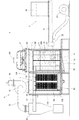
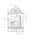
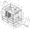
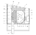
図1ないし図5を参照する。
Embodiment
The present invention will be described in detail based on the embodiments shown in the drawings.
Please refer to FIG. 1 to FIG.
温風発生装置Aは、燃焼炉1と、燃焼炉1の燃焼室10内に塊状燃料を空気によって吹き入れて供給する燃料供給装置2と、燃焼室10内に設けられた火格子装置3と、燃焼室10内に供給された火格子装置3上の塊状燃料に着火させるバーナー4と、燃焼室10から送られる燃焼ガスと送風機105から送られる空気との熱交換を行う熱交換装置5を備えている。
The hot air generator A includes a
また、熱交換装置5につながり、燃焼炉1に沿って燃焼室10とは区画されて設けられている送気空間部101と、熱交換装置5に送られて熱交換を行った燃焼ガスをサイクロン(集塵機)60を介し外部へ排出する排気装置6と、熱交換装置5で熱交換によって得られた温風を外部へ排出する温風排出口103とを備えている。以下、各部について詳細に説明する。
Further, the
(燃焼炉1)
燃焼炉1は、アングル部材で組み立てられたフレーム(符号省略)の前後(図1で右側が前、左側が後)、左右、上下の六面を鋼板製の外面板(側面側は図示省略)で囲んだ中空構造の筺体100内部の前側に設置されている。
燃焼炉1は、八面の側板11と八角形の天板12及び底板13によって構成され、各側板11でつくられた八角筒体の上端を天板12で、下端を底板13で閉塞した構造である。各側板11には、それぞれ多数の通気孔110が形成されている。燃焼炉1の底板13よりやや上方には、火格子装置3が設けられている。
(Combustion furnace 1)
The
The
(火格子装置3)
燃焼炉1の燃焼室10内には火格子装置3が設置されている。火格子装置3は、八角形の燃料支持床30を有している。燃料支持床30は鋼板で形成され、片側(後述する燃料供給装置2の供給管22側)の約1/2の広さの分だけ、塊状燃料の落下を防止し燃焼ガスを下側から取り入れる通孔31が多数形成されている。
(Grate device 3)
A
燃料支持床30の略中央部には、空気供給筒32が立設されている。空気供給筒32は下端が開口され、上端は天板320で閉塞されている。空気供給筒32の筒壁321には、全周面に亘って適宜数の空気供給孔322が設けられている。空気供給筒32の大きさ(高さ、直径)は、燃焼室10の空間部の大きさ等を加味して適宜設定される。燃料支持床30の下方は、底板13を底とする燃焼灰を溜める内部ピット33を構成する空間となっている。
An
(バーナー4)
また、燃焼炉1の図2において右側の側板11には、バーナー4が火炎口40を前記燃料支持床30のやや上側の燃焼室10内に導入して設置されている。バーナー4は、運転初期(温風発生装置起動時)において、燃焼炉1内の温度を上昇させると共に火格子装置3の燃料支持床30上に堆積した塊状燃料に早期に着火するためのオイルバーナーである。
(Burner 4)
Further, the
燃焼炉1の燃焼室10内において、バーナー4と後述する燃料供給装置2の供給管22の間の幅狭の側板11内面には、誘導板14が内方へ突出して取り付けられている。誘導板14は、燃焼室10内に燃料供給装置2から供給されて燃焼室10内で旋回する空気と塊状燃料の一部を火格子装置3の空気供給筒32の方向に、かつ斜め下方向に誘導するように傾斜させてある。
In the
また、燃焼室10において、各側板11の内面側には、燃焼ガスや燃え滓が後述する上方の排気側へ上昇するのを阻害又は邪魔をする阻害板15が取り付けられている。阻害板15は、八角環状のフランジ形状であり、前記燃料支持床30と平行に所要の同幅で内方向へ突出させて、全内周にわたり設けられている。
なお、燃焼炉1の後部側(熱交換装置5側)の側板11の上部は開口され、この開口部(符号省略)には、燃焼ガスを誘導する導出排気路16が後方の熱交換装置5側へ延長して設けてある。
Further, in the
In addition, the upper part of the
燃焼炉1の前部には、前記燃料支持床30より上側に、前記筺体100の前部外面板106に通じる四角形の覗き窓17が形成されている。覗き窓17は、耐火ガラス(符号省略)を有し、燃焼室10内を視認することができる。また、前記内部ピット33の前部には、蓋(符号省略)を有する灰掻き出し口18が形成されている。なお、燃焼炉1内に塊状燃料を供給する燃料供給装置については、後述する。
At the front part of the
(熱交換装置5)
筺体100内において、燃焼炉1の後方には熱交換装置5が設置されている。筺体100内には、燃焼炉1と熱交換装置5を囲繞するように送気空間部101が設けられている。
熱交換装置5は、上部に導入排気路50を有している。導入排気路50には、前記燃焼炉1から延長された導出排気路16が接続されている。
(Heat exchange device 5)
A
The
導入排気路50の後方には、燃焼ガスを熱交換装置5内に導入する導入排気路50と、導入排気路50とは区画板59で区画され、燃焼ガスを熱交換装置5内から排出する導出排気路51が設けられている。導出排気路51には、後述するサイクロン60に繋がる吸引排気路52が接続されている。また、熱交換装置5は、下部に中継排気路53を有している。
Behind the
熱交換装置5は、所要の間隔を設けて送気空間部101に接して垂直に配され、外面に多数のフィンを設けた多数の通風管54を備えている。各通風管54の上端の開口部(符号省略)は、前記導入排気路50と導出排気路51の内部に導入されている。また、各通風管54の下端の開口部(符号省略)は、前記中継排気路53の内部に導入されている。
The
前記筺体100の後部外面板102には、その口縁部分に円管が取り付けられた温風排出口103が形成されている。筺体100の天部には、前側の一部(燃焼炉1の上方)が円形に開口された天部外面板104が取り付けてある。天部外面板104には、送気空間部101に外部空気を送風できるようにして送風機105が取り付けられている。送風機105から送気空間部101内に送られる外部空気は、後で説明するように燃焼炉1や熱交換装置5で加温されて温風排出口103から装置外部へ温風として排出される。
The rear
(排気装置6)
筺体100の天部外面板104の後側には、排気装置6が設置されている。排気装置6は、天部外面板104に固定されている排気ブロワ61を備えている。排気ブロワ61の吸引管62は、サイクロン60に接続されており、更にサイクロン60には前記したように熱交換装置5からの吸引排気路52が接続されている。また、排気ブロワ61の排気管63は、例えば農業用ハウス内での使用において、燃焼ガスをハウス外に排気するように配管することができる。
(Exhaust device 6)
An
なお、筺体100内に送気空間部101が設けられることにより、燃焼炉1と熱交換装置5の周りは、鋼板で形成された二重構造となっており、燃焼炉1の壁面は送気空間部101を通る空気により常時冷却されて各外面板102、104、106(図示していない側面側の外面板を含む)の壁面温度が鋼板の許容温度以上に上昇しないようにしてあり、安全を図っている。
In addition, by providing the
(燃料供給装置2)
燃焼炉1の覗き窓17側には、塊状燃料を燃焼炉1内に供給する燃料供給装置2が設けられている。燃料供給装置2は、塊状燃料を貯留するホッパ20を有し、その下部の排出部(符号省略)には、燃焼炉1方向へ向けてスクリューコンベヤ21が設けられている。
(Fuel supply device 2)
On the
スクリューコンベヤ21の排出部(符号省略)は、覗き窓17の横の側板11を貫通して燃焼室10内に導入されている供給管22の中間部に接続されている。また、供給管22の前端には、給気ブロワ23が接続されている。これにより、給気ブロワ23から送られた空気は、スクリューコンベヤ21を通り供給される塊状燃料と共に燃焼室10内に吹き入れられるようになっている。
A discharge portion (reference numeral omitted) of the
(作用)
図3を主に参照する。
温風発生装置Aは、例えば農業用ハウス内に設置してハウス内を温めるために使用される。温風発生装置Aの運転においては、まず、燃料供給装置2から燃焼炉1の燃焼室10内に木質チップや木質ペレット等の塊状燃料9が空気によって吹き入れられて供給される。供給された塊状燃料9は、火格子装置3の燃料支持床30上に堆積する。なお、あらかじめ手作業で、燃焼炉1内の燃料支持床30上に塊状燃料9を適量堆積させておいてもよい。
(Function)
Refer mainly to FIG.
The hot air generator A is used, for example, for installing in an agricultural house and heating the house. In the operation of the hot air generator A, first, the
そして、バーナー4によって塊状燃料9に着火され、給気ブロワ23と排気ブロワ61が作動し、燃焼炉1内に空気が送られることにより塊状燃料9は自燃する。そして、ある程度自燃が進んで燃焼炉1内の温度が十分に上昇したところで、燃料供給装置2から塊状燃料9が空気と共に追加供給される。
Then, the
燃焼ガスは、燃料供給装置2の給気ブロワ23から供給管22を通り空気が供給されることにより火格子装置3の燃料支持床30の上方で空気供給筒32を中心に旋回し、旋回する空気を含む燃焼ガスと塊状燃料9の一部は、誘導板14によって火格子装置3の空気供給筒32の方向、かつ斜め下方向へ誘導される。
The combustion gas swirls around the
これにより、空気供給筒32の周囲には塊状燃料9が集積され、塊状燃料9の中にある空気供給筒32の空気供給孔322からは、塊状燃料9に対して放射状に空気が送られると共に、誘導板14により炎を含む燃焼ガスが空気供給筒32方向へ誘導される。更に、燃焼ガスは、上方の排気側である導出排気路16へ直ちに上昇するのではなく、阻害板15があることにより上昇するのが阻害又は邪魔される。
As a result, the
これにより、燃焼ガスは、燃焼室10内において誘導板14と阻害板15により、阻害板15よりも下方での滞留時間が比較的長くなり、未燃焼物の少ない完全燃焼に近い高効率での燃焼が行われ、未燃焼物が熱交換装置5に送られて各排気路50、51、52や各通風管54に溜まり、熱交換の効率が低下したり部材の腐蝕の原因になること等を防止できる。
Thereby, the residence time in the
なお、前記誘導板14によれば、空気供給筒32の周りを旋回する燃焼ガスに乱れをつくり、燃焼ガスは効果的に撹拌されるので、未燃焼物への着火性が向上し、燃焼継続性の向上が図られるようである。また、塊状燃料9も燃焼室10内でランダムに飛散して燃料支持床30上に落下し、各側板11の近くに偏って堆積することが防止される。したがって、燃焼室10内において、均一でムラのない安定的な燃焼が可能になる。
According to the
送風機105から送られる空気(外気)は、燃焼炉1に触れて熱交換を行った後で熱交換装置5で熱交換が行われ、温風排出口103から農業用ハウス内に排出され、ハウス内の空気を温める。なお、ハウス内に排出される温風は、一旦燃焼炉1に触れて熱交換が行われ加温されることにより、熱をより無駄なく利用した高効率での熱交換を行うことができる。
The air (outside air) sent from the
また、燃焼炉1から排出された高温の燃焼ガスは、導出排気路16から導入排気路50に導入され、所要の通風管54を通り、中継排気路53を通り、所要の通風管54を通って、前記送気空間部101を通る空気との熱交換を行い、導出排気路51から吸引排気路52を通ってサイクロン60に導入される。
Further, the high-temperature combustion gas discharged from the
燃焼ガスはサイクロン60によって集塵が行われ、燃え滓が回収される。また、集塵が行われた燃焼ガスは、冷却されながら排気ブロワ61から排気管63を通って、農業用ハウス外部へ排出される。
The combustion gas is collected by the
なお、本明細書で使用している用語と表現は、あくまでも説明上のものであって、なんら限定的なものではなく、本明細書に記述された特徴およびその一部と等価の用語や表現を除外する意図はない。また、本発明の技術思想の範囲内で、種々の変形が可能であることは言うまでもない。 Note that the terms and expressions used in this specification are merely explanatory and are not limiting at all, and terms and expressions equivalent to the features described in this specification and parts thereof. There is no intention to exclude. It goes without saying that various modifications are possible within the scope of the technical idea of the present invention.
A 温風発生装置
1 燃焼炉
10 燃焼室
11 側板
110 通気孔
12 天板
13 底板
14 誘導板
15 阻害板
16 導出排気路
17 覗き窓
18 灰掻き出し口
2 燃料供給装置
20 ホッパ
21 スクリューコンベヤ
22 供給管
23 給気ブロワ
3 火格子装置
30 燃料支持床
31 通孔
32 空気供給筒
320 天板
321 筒壁
322 空気供給孔
33 内部ピット
4 バーナー
40 火炎口
5 熱交換装置
50 導入排気路
51 導出排気路
52 吸引排気路
53 中継排気路
54 通風管
59 区画板
6 排気装置
60 サイクロン
61 排気ブロワ
62 吸引管
63 排気管
100 筺体
101 送気空間部
102 後部外面板
103 温風排出口
104 天部外面板
105 送風機
106 前部外面板
9 塊状燃料
DESCRIPTION OF SYMBOLS A
Claims (3)
該燃焼炉(1)の燃焼室(10)内に塊状燃料を空気によって吹き入れて供給する燃料供給装置(2)と、
前記燃焼室(10)内に設けられた火格子装置(3)と、
前記燃焼室(10)内に供給された前記火格子装置(3)上の塊状燃料に着火させるバーナー(4)と、
前記燃焼室(10)から送られる燃焼ガスと送風機(105)から送られる空気との熱交換を行う熱交換装置(5)と、
該熱交換装置(5)に送られて熱交換を行った燃焼ガスを集塵機(60)を介し外部へ排出する排気装置(6)と、
前記熱交換装置(5)で熱交換によって得られた温風を外部へ排出する温風排出部(103)と、
を備えており、
前記火格子装置(3)は、
燃料支持床(30)と、
該燃料支持床(30)に立設されており、周壁(321)に適宜数の空気供給孔(322)が設けられている空気供給筒(32)と、
を備えており、
前記燃料供給装置(2)の供給部(22)が前記燃焼室内の一方側へ偏って設けられ、供給部(22)から供給される空気と塊状燃料が前記燃焼室(10)内の燃焼ガスを旋回させるようにしてあり、
前記燃焼室(10)の内壁部には、燃焼ガスが上方の排気側へ上昇するのを阻害する阻害部材(15)が設けられている、
温風発生装置。 A combustion furnace (1),
A fuel supply device (2) for supplying bulk fuel by blowing air into the combustion chamber (10) of the combustion furnace (1);
A grate device (3) provided in the combustion chamber (10);
A burner (4) for igniting the bulk fuel on the grate device (3) supplied into the combustion chamber (10);
A heat exchange device (5) for exchanging heat between the combustion gas sent from the combustion chamber (10) and the air sent from the blower (105);
An exhaust device (6) that exhausts the combustion gas sent to the heat exchange device (5) and subjected to heat exchange through the dust collector (60);
A hot air discharger (103) for discharging the hot air obtained by heat exchange in the heat exchange device (5) to the outside;
With
The grate device (3)
A fuel support floor (30);
An air supply cylinder (32) which is erected on the fuel support floor (30) and has an appropriate number of air supply holes (322) provided on the peripheral wall (321);
With
A supply unit (22) of the fuel supply device (2) is provided to be biased toward one side of the combustion chamber, and air and bulk fuel supplied from the supply unit (22) are combustion gases in the combustion chamber (10). Is made to turn,
The inner wall of the combustion chamber (10) is provided with an inhibition member (15) that inhibits combustion gas from rising to the upper exhaust side.
Hot air generator.
請求項1記載の温風発生装置。 The combustion chamber (10) includes a derivative (14) that guides a part of the air and the bulk fuel supplied from the fuel supply device (2) in the direction of the air supply cylinder (32).
The warm air generator according to claim 1.
請求項1又は2記載の温風発生装置。 It has an air supply space (101) surrounding the combustion furnace (1) and the heat exchange device (5), and the air supply space (101) is separated from the combustion chamber (10) along the combustion furnace (1). The air sent from the blower (105) is configured so that heat exchange is performed in the heat exchange device (5) after performing heat exchange by touching the combustion furnace (1).
The warm air generator according to claim 1 or 2.
Priority Applications (1)
| Application Number | Priority Date | Filing Date | Title |
|---|---|---|---|
| JP2011113923A JP2012242018A (en) | 2011-05-20 | 2011-05-20 | Hot air generation device |
Applications Claiming Priority (1)
| Application Number | Priority Date | Filing Date | Title |
|---|---|---|---|
| JP2011113923A JP2012242018A (en) | 2011-05-20 | 2011-05-20 | Hot air generation device |
Publications (1)
| Publication Number | Publication Date |
|---|---|
| JP2012242018A true JP2012242018A (en) | 2012-12-10 |
Family
ID=47463917
Family Applications (1)
| Application Number | Title | Priority Date | Filing Date |
|---|---|---|---|
| JP2011113923A Withdrawn JP2012242018A (en) | 2011-05-20 | 2011-05-20 | Hot air generation device |
Country Status (1)
| Country | Link |
|---|---|
| JP (1) | JP2012242018A (en) |
Cited By (2)
| Publication number | Priority date | Publication date | Assignee | Title |
|---|---|---|---|---|
| CN102798118A (en) * | 2012-07-17 | 2012-11-28 | 胡光 | Cyclone boiler |
| JP2019158190A (en) * | 2018-03-09 | 2019-09-19 | 宏和 平井 | Air gradual increasing type biomass combustion gas generating device and biomass steam power generating system using the same |
-
2011
- 2011-05-20 JP JP2011113923A patent/JP2012242018A/en not_active Withdrawn
Cited By (3)
| Publication number | Priority date | Publication date | Assignee | Title |
|---|---|---|---|---|
| CN102798118A (en) * | 2012-07-17 | 2012-11-28 | 胡光 | Cyclone boiler |
| CN102798118B (en) * | 2012-07-17 | 2015-02-25 | 胡光 | Cyclone boiler |
| JP2019158190A (en) * | 2018-03-09 | 2019-09-19 | 宏和 平井 | Air gradual increasing type biomass combustion gas generating device and biomass steam power generating system using the same |
Similar Documents
| Publication | Publication Date | Title |
|---|---|---|
| CN106537037B (en) | Smokeless incinerator and the system using the smokeless incinerator | |
| KR101587377B1 (en) | Reverse combustion firewood stove | |
| WO2016201740A1 (en) | Flue gas recirculation combustion apparatus | |
| RU2619434C1 (en) | Installation for solid fuel combustion | |
| CN105889901A (en) | Fixed grate boiler allowing square bundle of stalks to be combusted | |
| JP2012241981A (en) | Solid fuel combustion device | |
| JP2012017872A (en) | Incineration device | |
| JP4766562B2 (en) | Wood pellet fired steam boiler | |
| CN104006376A (en) | Curing barn combustion chamber with double layers of inclined fire grates | |
| PL224288B1 (en) | Central heating boiler | |
| RU2363888C1 (en) | Water-heating solid-propellant boiler | |
| JP5281806B2 (en) | Wood pellet combustion equipment | |
| CN102261739B (en) | Biomass energy hot blast stove | |
| CN201322439Y (en) | Pulverized-coal burnt horizontal-type hot fume generating furnace | |
| CN205102108U (en) | Biomass particle combustion furnace | |
| KR20180080055A (en) | Firewood boiler | |
| RU2419050C1 (en) | Heat generator operating on straw | |
| KR20130000688U (en) | Combustion apparatus with improved combustion efficiency | |
| RU2661516C2 (en) | Solid-fuel gas-generated boiler | |
| JP6621028B2 (en) | Rice husk combustion hot water boiler and combustion method | |
| JP2016166723A (en) | Compound steam boiler employing chain stoker fore grate for solid fuel | |
| KR101369605B1 (en) | Boiler | |
| JP2011080614A (en) | Warm air heater | |
| KR101323388B1 (en) | Pellet combustion device | |
| KR101344606B1 (en) | Combusion apparatus of pellet fuel |
Legal Events
| Date | Code | Title | Description |
|---|---|---|---|
| RD02 | Notification of acceptance of power of attorney |
Free format text: JAPANESE INTERMEDIATE CODE: A7422 Effective date: 20130402 |
|
| A300 | Withdrawal of application because of no request for examination |
Free format text: JAPANESE INTERMEDIATE CODE: A300 Effective date: 20140805 |