JP2012251380A - Hinge structure for swing door - Google Patents

Hinge structure for swing door Download PDF

Info

Publication number
JP2012251380A
JP2012251380A JP2011125682A JP2011125682A JP2012251380A JP 2012251380 A JP2012251380 A JP 2012251380A JP 2011125682 A JP2011125682 A JP 2011125682A JP 2011125682 A JP2011125682 A JP 2011125682A JP 2012251380 A JP2012251380 A JP 2012251380A
Authority
JP
Japan
Prior art keywords
hinged door
support shaft
hinge
hinges
door
Prior art date
Legal status (The legal status is an assumption and is not a legal conclusion. Google has not performed a legal analysis and makes no representation as to the accuracy of the status listed.)
Granted
Application number
JP2011125682A
Other languages
Japanese (ja)
Other versions
JP5715888B2 (en
Inventor
Hayato Yagi
準人 八木
Current Assignee (The listed assignees may be inaccurate. Google has not performed a legal analysis and makes no representation or warranty as to the accuracy of the list.)
Yagi KK
Original Assignee
Yagi KK
Priority date (The priority date is an assumption and is not a legal conclusion. Google has not performed a legal analysis and makes no representation as to the accuracy of the date listed.)
Filing date
Publication date
Application filed by Yagi KK filed Critical Yagi KK
Priority to JP2011125682A priority Critical patent/JP5715888B2/en
Publication of JP2012251380A publication Critical patent/JP2012251380A/en
Application granted granted Critical
Publication of JP5715888B2 publication Critical patent/JP5715888B2/en
Expired - Fee Related legal-status Critical Current
Anticipated expiration legal-status Critical

Links

Images

Landscapes

  • Hinges (AREA)

Abstract

【課題】開き戸を固定する蝶番の構造を工夫するだけの簡単な構造で自動的に開き戸を閉めることができる開き戸の蝶番構造を提供する。
【解決手段】枠体3の一面に開き戸4の一面を2組の蝶番1、2で固定し、下側蝶番1の支持軸11および上側蝶番2の支持軸21の周りに開き戸4を回転させる構造になっており、2組の蝶番1、2のうち、開き戸4の上側で固定する上側蝶番2は、開き戸4が閉まった状態で、その支持軸21の位置が、開き戸4の平面と平行なy軸方向で、開き戸4の取付け側の端部4aからの距離y2が、下側蝶番1の支持軸11の端部4aからの距離y1(図1の例では、y1=0)よりも大きくなるように形成されている。
【選択図】図1
A hinge structure for a hinged door capable of automatically closing the hinged door with a simple structure that only devise the structure of the hinge for fixing the hinged door is provided.
One side of a hinged door 4 is fixed to one surface of a frame 3 with two pairs of hinges 1 and 2, and the hinged door 4 is rotated around a support shaft 11 of a lower hinge 1 and a support shaft 21 of an upper hinge 2. Of the two sets of hinges 1 and 2, the upper hinge 2 fixed on the upper side of the hinged door 4 is in a state where the hinged door 4 is closed and the position of the support shaft 21 is parallel to the plane of the hinged door 4. In the y-axis direction, the distance y2 from the end 4a on the attachment side of the hinged door 4 is greater than the distance y1 from the end 4a of the support shaft 11 of the lower hinge 1 (y1 = 0 in the example of FIG. 1). It is formed to be large.
[Selection] Figure 1

Description

本発明は、柱などを含む枠体の一面に蝶番により開き戸が固定され、蝶番の回転軸(支持軸)の周りに開き戸を開閉する開き戸の蝶番構造に関する。さらに詳しくは、蝶番の簡易な構造だけで開けた開き戸が自動的に閉まる構造の開き戸の蝶番構造に関する。   The present invention relates to a hinge structure of a hinged door in which a hinged door is fixed to one surface of a frame including a pillar or the like by a hinge, and the hinged door is opened and closed around a rotation axis (support shaft) of the hinge. More specifically, the present invention relates to a hinge structure of a hinged door having a structure in which a hinged door that is opened only by a simple hinge structure is automatically closed.

従来の開き戸は、1個または複数個の蝶番で枠体に固定して、蝶番の回転軸の周りに開き戸を回転させることにより開閉する構造に形成されている。このような開き戸は、一般の家屋、事務所、工場、公衆トイレなど幅広い分野で用いられている。   A conventional hinged door is formed in a structure that is fixed to a frame with one or a plurality of hinges and is opened and closed by rotating the hinged door around a rotation axis of the hinge. Such hinged doors are used in a wide range of fields such as general houses, offices, factories, and public toilets.

このような開き戸を開けた後に、自動的に閉まるようにするためには、たとえば図10に示されるように、枠体51の上部に駆動装置52を取り付け、駆動装置52に設けられている回転軸53に、たとえば伸縮式または折畳み式としたアーム54の一端を固定し、他端を開き戸55に固定して、回転軸53のトルクにより、開き戸55を自動的に閉める装置などが知られている(たとえば特許文献1参照)。56は通常の蝶番で、一定の長さを有する支持軸の周りに開き戸55が回転するため、上下の蝶番56の支持軸は一直線上にある。   In order to automatically close after opening such a hinged door, for example, as shown in FIG. 10, a driving device 52 is attached to the upper portion of the frame 51, and the rotation provided in the driving device 52. For example, a device is known in which one end of a telescopic or foldable arm 54 is fixed to the shaft 53, the other end is fixed to the hinged door 55, and the hinged door 55 is automatically closed by the torque of the rotating shaft 53. (For example, refer to Patent Document 1). Reference numeral 56 denotes a normal hinge. Since the hinged door 55 rotates around a support shaft having a certain length, the support shafts of the upper and lower hinges 56 are in a straight line.

特開2008−208645号公報JP 2008-208645 A

前述のように、事務所や工場などの厳密に開き戸の閉鎖を必要とする場所であれば、駆動装置を取り付けて必ず閉鎖することができるようにする必要があるが、この場合扉を開ける動作には弱者(お年寄り、子供)の力では困難な場合が多々ある。また、家庭の洗面所とか、公衆トイレで不使用時に扉が閉まっていることが美観的に好ましいという程度の場合には、ある程度力を要する駆動装置を取り付ける値打ちはなく、弱者でも容易に開けられる簡単な構造で開き戸を閉鎖することができることが好ましい。   As mentioned above, it is necessary to install a drive device to ensure that the door is strictly closed, such as in an office or factory, but in this case, the door is opened. In many cases, it is difficult for the weak (old people, children). Also, if it is aesthetically preferable that the door is closed when not in use at a bathroom or in a public toilet, there is no value for attaching a drive device that requires some force, and even the weak can easily open it. It is preferable that the hinged door can be closed with a simple structure.

本発明は、このような状況に鑑みてなされたもので、開き戸を固定する蝶番の構造を工夫するだけの簡単な構造で自動的に開き戸を閉めることができ、かつ、小さな力で容易に開けることができる開き戸の蝶番構造を提供することを目的とする。   The present invention has been made in view of such a situation, and can automatically close the opening door with a simple structure simply by devising the structure of a hinge for fixing the opening door, and can be easily opened with a small force. It aims to provide hinge structure of hinged door that can.

本発明による開き戸の蝶番構造は、枠体の一面に開き戸の一面を2組の蝶番で固定し、該蝶番の支持軸の周りに開き戸を回転させることにより該開き戸を開閉する開き戸の蝶番構造であって、前記2組の蝶番のうち、開き戸の上側で固定する上側蝶番の支持軸の位置の、前記開き戸の取付け側の端部からの距離が、該開き戸の平面と平行な方向で、前記2組の蝶番のうち下側で固定する下側蝶番の支持軸の前記端部からの距離よりも大きくなるように、前記2組の蝶番が形成されている。   The hinge structure of the hinged door according to the present invention is a hinge structure of the hinged door that opens and closes the hinged door by fixing the one face of the hinged door to one surface of the frame with two sets of hinges and rotating the hinged door around the support shaft of the hinge. In the two sets of hinges, the position of the support shaft of the upper hinge fixed on the upper side of the hinged door from the end on the attachment side of the hinged door is in a direction parallel to the plane of the hinged door, The two sets of hinges are formed so as to be larger than the distance from the end portion of the support shaft of the lower hinge fixed at the lower side of the two sets of hinges.

ここに枠体とは、開き戸を固定するものを意味し、柱や他のドアなど開き戸の取付けを可能にする全てのものを含む意味である。また、開き戸の平面とは、開き戸の側面とは異なる平面で、幅広面を意味している。   A frame means here what fixes a hinged door, and the meaning including all things which enable attachment of a hinged door, such as a pillar and other doors. Moreover, the plane of a hinged door is a plane different from the side surface of a hinged door, and means the wide surface.

前記2組の蝶番のそれぞれは、2枚の羽根の一方の羽根に形成される支持軸が突棒で形成され、他方の羽根に形成される該支持軸に対向する部分が、該突棒を受け入れる凹部で形成され、該支持軸の先端部と前記凹部の底部との突き当てで前記開き戸を支持する構造に形成され、かつ、少なくとも前記支持軸の先端部が凸状曲面に形成されていることが、上下の蝶番構造で支持軸が一致しないことにより開き戸が傾いた状態になっても、点接触になって開き戸の回転を自由に行うことができるため好ましい。   In each of the two sets of hinges, a support shaft formed on one of the two blades is formed with a projecting rod, and a portion facing the support shaft formed on the other blade has the projecting rod. It is formed with a recess to receive, is formed in a structure that supports the hinged door by abutting the tip of the support shaft and the bottom of the recess, and at least the tip of the support shaft is formed in a convex curved surface Even when the hinged door is tilted because the support shafts do not coincide with each other in the upper and lower hinge structures, it is preferable because the hinged door can be freely rotated by the point contact.

また、前記2組の蝶番のうち、前記下側蝶番の支持軸の前記開き戸の平面からの距離が、前記上側蝶番の支持軸の前記開き戸の平面からの距離よりも大きくなるように前記2組の蝶番が形成されていることにより、開き戸を自動的に閉める力がさらに大きくなるため好ましい。   Further, of the two sets of hinges, the distance between the support shaft of the lower hinge and the plane of the hinged door is larger than the distance of the support shaft of the upper hinge from the plane of the hinged door. This is preferable because the force for automatically closing the hinged door is further increased.

前記2組の蝶番のそれぞれが、支持軸を有する支持部材と、該支持軸を受ける円筒部が形成された受け部材とからなり、該支持部材および受け部材が前記開き戸の内部に設けられるグレビティ型の蝶番構造であり、前記下側蝶番の支持部材は、先端部が凸状曲面に形成された支持軸を有し、該支持軸の先端と前記受け部材の円筒部頂部との突き当てで前記開き戸が支持され、前記上側蝶番は、前記支持軸と前記円筒部とが前記開き戸の傾きを許容できる隙間を有するように形成される構造にすることもできる。すなわち、グレビティ型構造の蝶番構造でも、上下の蝶番で支持軸の位置をオフセットさせることにより、自動的に開き戸を閉めることができる。   Each of the two sets of hinges includes a support member having a support shaft and a receiving member in which a cylindrical portion for receiving the support shaft is formed, and the support member and the receiving member are provided inside the hinged door. The support member of the lower hinge has a support shaft having a tip formed in a convex curved surface, and abutting between the tip of the support shaft and the top of the cylindrical portion of the receiving member A hinged door is supported, and the upper hinge may be structured such that the support shaft and the cylindrical portion have a gap that allows the tilt of the hinged door. In other words, even in the case of a hinge structure of a gravitational structure, the hinged door can be automatically closed by offsetting the position of the support shaft with the upper and lower hinges.

本発明の開き戸の蝶番構造によれば、開き戸を枠体などに固定する2組の蝶番構造のうち、開き戸の上側で固定する上側蝶番は、その支持軸の位置が、開き戸の平面と平行な方向で、開き戸の取付け側の端部からの距離が、2組の蝶番のうち下側で固定する下側蝶番の支持軸の開き戸の取付け側の端部からの距離よりも大きくなるように形成されているため、開き戸が開かれると、開き戸の底面側が枠体に近い側で支持され、上部側は枠体から離れた位置で支持されているため、開けられた開き戸は閉まろうとする力が働く。その結果、開き戸を開けると必ずその開き戸の重力の一部により開き戸を閉めようとする力が作用し、自動的に閉鎖する。その結果、公衆トイレのように、公衆が使用してトイレから出るときに、きちんとドアを閉めなくても、自動的にドアが閉まり、美観の面からも非常に好ましい。   According to the hinge structure of the hinged door of the present invention, of the two hinge structures for securing the hinged door to the frame or the like, the upper hinge secured on the upper side of the hinged door has a support shaft parallel to the plane of the hinged door. In the direction, the distance from the end of the hinged door is larger than the distance of the hinged support shaft of the lower hinge that is fixed at the lower of the two hinges. Therefore, when the hinged door is opened, the bottom side of the hinged door is supported on the side close to the frame, and the upper side is supported at a position away from the frame, so that the opened hinged door has a force to close. work. As a result, whenever the hinged door is opened, a force to close the hinged door acts by a part of the gravity of the hinged door, and the door is automatically closed. As a result, like a public toilet, when the public uses and exits the toilet, the door is automatically closed without being properly closed, which is also preferable from the viewpoint of aesthetics.

この自動的に閉鎖する力は、下側蝶番の支持軸の開き戸の平面からの距離が、上側蝶番の支持軸の開き戸の平面からの距離よりも大きくなるように前記2組の蝶番を形成することにより、より一層ドアが閉まる側に傾き、容易に開き戸を自動的に閉めることができる。下側蝶番および上側蝶番の両方をオフセットすることにより、速いスピードで開き戸を確実に閉鎖することができるのみならず、開き戸を90°より大きく開いた場合(たとえば150°程度)でも、自動的に閉鎖することができる。   This automatically closing force forms the two sets of hinges such that the distance of the lower hinge support shaft from the plane of the hinged door is greater than the distance of the upper hinge support shaft from the plane of the hinged door. Thus, the door can be further tilted and the door can be easily closed automatically. By offsetting both the lower and upper hinges, not only can the hinged door be reliably closed at a fast speed, but also automatically when the hinged door is opened more than 90 ° (eg around 150 °). Can be closed.

さらに、蝶番の支持軸で開き戸を支持しながら、その接点を凸状の曲面に形成することにより、開き戸を支える支持部が殆ど点接触になり、開き戸に傾きが生じてもスムースに開き戸を回転させることができる。   Furthermore, by supporting the hinged door with the hinge support shaft and forming the contact point on the convex curved surface, the support part that supports the hinged door is almost point contact, and even if the hinged door tilts, the hinged door rotates smoothly. Can be made.

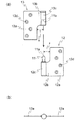
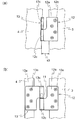
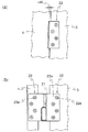
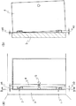
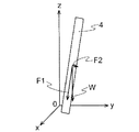
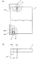
(a)は本発明の開き戸の蝶番構造の一実施形態を示す正面説明図、(b)はそのB−B断面説明図である。(A) is front explanatory drawing which shows one Embodiment of the hinge structure of the hinged door of this invention, (b) is the BB cross-section explanatory drawing. 図1の下側蝶番の分解説明図である。It is decomposition | disassembly explanatory drawing of the lower hinge of FIG. 図2の蝶番を図1の枠体3および開き戸4に取り付けて90°開いたとき(a)および180°開いたとき(b)の蝶番取付け側から見た説明図である。It is explanatory drawing seen from the hinge attachment side when attaching the hinge of FIG. 2 to the frame 3 and the hinged door 4 of FIG. 1 and opening 90 degrees (a) and 180 degrees (b). 図1の上側蝶番の分解説明図、上面説明図および(a)のC−C断面説明図である。It is an exploded explanatory view of the upper hinge of FIG. 1, an upper surface explanatory drawing, and CC sectional explanatory drawing of (a). 図4の蝶番を図1の枠体3および開き戸4に取り付けて90°開いたとき(a)および180°開いたとき(b)の蝶番取付け側から見た説明図である。It is explanatory drawing seen from the hinge attachment side when attaching the hinge of FIG. 4 to the frame 3 and the hinged door 4 of FIG. 1 and opening 90 degrees (a) and 180 degrees (b). 図1の状態で、開き戸を90°開いたときの正面図(a)およびそのB−B断面説明図(b)である。It is the front view (a) when the hinged door is opened 90 degrees in the state of FIG. 1, and its BB cross-section explanatory drawing (b). 図6(a)の状態で開き戸が自動的に閉まる理由を説明するための、図6(a)の開き戸の傾きを誇張して力の関係を示した説明図である。It is explanatory drawing which exaggerated the inclination of the hinged door of Fig.6 (a), and showed the relationship of force for demonstrating the reason a hinged door closes automatically in the state of Fig.6 (a). 本発明の開き戸の蝶番構造の他の実施形態を示す正面説明図(a)および上面説明図(b)である。It is front explanatory drawing (a) and upper surface explanatory drawing (b) which show other embodiment of the hinge structure of the hinged door of this invention. 図8の上側蝶番および下側蝶番の全体斜視図である。FIG. 9 is an overall perspective view of the upper hinge and the lower hinge of FIG. 8. 従来の開き戸を自動的に閉める構造例の説明図である。It is explanatory drawing of the structural example which closes the conventional hinged door automatically.

つぎに、図面を参照しながら本発明の開き戸の蝶番構造について説明をする。本発明による開き戸の蝶番構造は、図1に開き戸を閉めた状態の正面説明図およびそのB−B断面説明図が、図6に開き戸を90°開いたときの同様の正面説明図および断面説明図が示されるように、枠体3の一面に開き戸4の一面を2組の蝶番1、2で固定し、下側蝶番1の支持軸11および上側蝶番2の支持軸21の周りに開き戸4を回転させる構造になっている。そして、2組の蝶番1、2のうち、開き戸4の上側で固定する上側蝶番2は、開き戸4が閉まった状態(図1の状態)で、その支持軸21の位置が、開き戸4の平面と平行なy軸方向で、開き戸4の取付け側の端部4aからの距離y2が、下側蝶番1の支持軸11の端部4aからの距離y1(図1の例では、y1=0)よりも大きくなるように(図1(a)参照)形成されている。なお、図1で5は、開き戸4を開閉するための取っ手であるが、簡易な構造にする場合には、無くてもよいし、設ける場合には、通常の簡単なロック機構を有していても良いが、とくに制限されない。また、図1に示されるように、開き戸4を閉めた状態で開き戸4の平面と垂直な方向をx軸、開き戸4の平面と平行な方向をy軸、開き戸4の高さ方向をz軸として以下の説明をする。   Next, the hinge structure of the hinged door of the present invention will be described with reference to the drawings. The hinge structure of the hinged door according to the present invention is the same as the front explanatory view and the sectional explanation when the hinged door is opened 90 degrees in FIG. As shown in the figure, one surface of the hinged door 4 is fixed to one surface of the frame 3 with two sets of hinges 1 and 2, and the hinged door 4 is rotated around the support shaft 11 of the lower hinge 1 and the support shaft 21 of the upper hinge 2. It is structured to rotate. Of the two sets of hinges 1 and 2, the upper hinge 2 fixed on the upper side of the hinged door 4 is in a state where the hinged door 4 is closed (the state of FIG. 1), and the position of the support shaft 21 is the plane of the hinged door 4. Is a distance y2 from the end 4a on the mounting side of the hinged door 4 in the y-axis direction parallel to the distance y1 from the end 4a of the support shaft 11 of the lower hinge 1 (y1 = 0 in the example of FIG. 1). (See FIG. 1A). In FIG. 1, 5 is a handle for opening and closing the hinged door 4. However, in the case of a simple structure, it may be omitted, and when provided, it has a normal simple lock mechanism. However, it is not particularly limited. Further, as shown in FIG. 1, with the hinged door 4 closed, the direction perpendicular to the plane of the hinged door 4 is the x axis, the direction parallel to the plane of the hinged door 4 is the y axis, and the height direction of the hinged door 4 is the z axis. The following explanation will be given.

図1に示される例では、上側蝶番1の支持軸21のy軸方向への距離y2が、下側蝶番1のy軸方向へのオフセットy1より大きいだけではなく、下側蝶番2は、その支持軸11の位置が、開き戸4の平面と垂直なx軸方向への突出距離x1が、上側蝶番2のx軸方向への突出距離x2より大きくなる(図1(b)参照)ように2組の蝶番1、2が形成されている。しかし、後述するように、この下側蝶番1の支持軸11の突出距離x1を大きくすることと、上側蝶番2の開き戸4と平行方向へのずれ(オフセット)y2を大きくすることの両方を具備する必要はなく、y軸方向へのオフセットy2をy1よりも大きくするだけで、開き戸4を自動的に閉めることができる。   In the example shown in FIG. 1, the distance y2 in the y-axis direction of the support shaft 21 of the upper hinge 1 is not only larger than the offset y1 in the y-axis direction of the lower hinge 1, but the lower hinge 2 The position of the support shaft 11 is 2 so that the protrusion distance x1 in the x-axis direction perpendicular to the plane of the hinged door 4 is larger than the protrusion distance x2 of the upper hinge 2 in the x-axis direction (see FIG. 1B). A pair of hinges 1, 2 is formed. However, as will be described later, both the projection distance x1 of the support shaft 11 of the lower hinge 1 and the deviation (offset) y2 of the upper hinge 2 in the direction parallel to the hinged door 4 are increased. The hinged door 4 can be automatically closed simply by making the offset y2 in the y-axis direction larger than y1.

下側蝶番1は、たとえば図2(a)に分解正面説明図、図2(b)にその上面説明図が示されるような構造になっている。すなわち、第1羽根部材12は、枠体3などに取り付ける取付け部12aと、その高さの半分程度の長さ部分だけ延長する延出部12bと、その先端部分が円筒状に丸められて形成される円筒部12cとを有し、その円筒部12cの内部に支持軸11が固定されている。この延出部12bは、支持軸11を開き戸4の平面から突出させるために、たとえば支持軸の中心までの距離が所望の長さxになるように形成されている。球面でも良いが、球面に限定されず、点接触のように小さい面積で相手方と接触できる構造であればよい。支持軸11は図2(a)に示されるように、先端部が凸状曲面11aに形成されている。第2羽根部材13も同様の構造に形成され、たとえば開き戸4の側面に固定する取付け部13aと、延出部13bと、その先端部に形成される円筒部13cとにより形成され、その円筒部13c内にストッパ部11bが形成されている。その円筒部13cとストッパ部11bとにより形成される凹部が支持軸11に嵌め合されることにより、第2羽根部材13に固定された開き戸4を、枠体3に固定された第1羽根部材12の支持軸11で回転自在に支持し得る構造になっている。すなわち、支持軸11の外径と凹部の内径とは、開き戸4が傾き得るスペースが形成されている。なお、12d、13dは、ネジ12e、13eで第1羽根部材12などを枠体3などに固定するための取付け孔である。   The lower hinge 1 has a structure, for example, as shown in an exploded front view in FIG. 2 (a) and a top view in FIG. 2 (b). That is, the first blade member 12 is formed by attaching a mounting portion 12a to be attached to the frame 3 or the like, an extending portion 12b extending by about half of its height, and a tip portion thereof being rounded into a cylindrical shape. The support shaft 11 is fixed to the inside of the cylindrical portion 12c. The extending portion 12b is formed such that the distance to the center of the support shaft is a desired length x, for example, in order to cause the support shaft 11 to protrude from the plane of the hinged door 4. Although it may be a spherical surface, it is not limited to a spherical surface, and any structure that can contact the other party with a small area such as point contact may be used. As shown in FIG. 2A, the support shaft 11 is formed with a convex curved surface 11a at the tip. The second blade member 13 is also formed in the same structure, and is formed by, for example, an attachment portion 13a that is fixed to the side surface of the hinged door 4, an extension portion 13b, and a cylindrical portion 13c that is formed at the tip portion thereof. A stopper portion 11b is formed in 13c. A first blade member fixed to the frame body 3 with the hinged door 4 fixed to the second blade member 13 by fitting a recess formed by the cylindrical portion 13 c and the stopper portion 11 b to the support shaft 11. The twelve support shafts 11 can be rotatably supported. That is, a space in which the hinged door 4 can tilt is formed between the outer diameter of the support shaft 11 and the inner diameter of the recess. In addition, 12d and 13d are attachment holes for fixing the first blade member 12 and the like to the frame body 3 and the like with screws 12e and 13e.

この第1羽根部材12や第2羽根部材13を、たとえば枠体3と開き戸4とが対向する面にそれぞれ取り付けるのではなく、枠体3および開き戸4の正面に取り付ける構造であれば、延出部12b、13bは取付け部12a、22aと同一面ではなく、90°曲げる構造にして延出部を形成することもできる。図1に示される例では、支持軸11の中心位置が、開き戸4の平面から距離x1だけオフセットして形成されている。なお、蝶番1、2をいずれの面に取り付ける場合でも、その取付け面には、蝶番1、2の形状に合せた窪みを形成し、枠体3や開き戸4などの表面に蝶番1、2の羽根部材12、22が出っ張らないようにすることができる。   If the first blade member 12 and the second blade member 13 are attached to the front surface of the frame 3 and the hinged door 4 instead of being attached to the surface where the frame 3 and the hinged door 4 face each other, for example, the extension The portions 12b and 13b are not flush with the attachment portions 12a and 22a, and the extending portions can be formed by bending 90 °. In the example shown in FIG. 1, the center position of the support shaft 11 is offset from the plane of the hinged door 4 by a distance x1. In addition, even when hinges 1 and 2 are attached to either surface, a recess corresponding to the shape of hinges 1 and 2 is formed on the attachment surface, and hinges 1 and 2 are formed on the surface of frame 3 or hinged door 4. It is possible to prevent the blade members 12 and 22 from protruding.

この第1羽根部材12の支持軸11に、第2羽根部材13の円筒部13cを嵌め合せることにより、支持軸11の凸状曲面11aで第2羽根部材13、すなわち開き戸4をほぼ点接触で支持しながら、開き戸4の開閉を自由に行うことができる。なお、第2羽根部材13の円筒部13c内に形成されるストッパ部11bは、図2に示される例では平面状であるが、凸曲面、凹曲面など他の形状でも構わない。この円筒部13cの内径と、支持軸11の凸部の最大径の部分とでは、前述のように、0.5〜1mm程度の隙間が形成されているため、第1羽根部材12の筒状部12cと第2羽部材13の筒状部13cとの芯が傾いても確実に支持しながら相互に自由に回転することができる。   By fitting the cylindrical portion 13c of the second blade member 13 to the support shaft 11 of the first blade member 12, the convex surface 11a of the support shaft 11 makes the second blade member 13, that is, the hinged door 4 almost point contact. The hinged door 4 can be freely opened and closed while being supported. In addition, although the stopper part 11b formed in the cylindrical part 13c of the 2nd blade | wing member 13 is planar shape in the example shown by FIG. 2, other shapes, such as a convex curved surface and a concave curved surface, may be sufficient. As described above, a gap of about 0.5 to 1 mm is formed between the inner diameter of the cylindrical portion 13c and the maximum diameter portion of the convex portion of the support shaft 11, and thus the cylindrical shape of the first blade member 12 is formed. Even if the cores of the portion 12c and the cylindrical portion 13c of the second wing member 13 are inclined, they can rotate freely while being reliably supported.

この第1羽根部材12を枠体3の内壁(開き戸と対向する面)に取付け孔12dを介して、ネジ12eにより固定し、第2羽根部材13を開き戸4の側面(枠体3と対向する面)に、取付け孔13を介して、ネジ13eにより固定して第1羽根部材12の支持軸11に第2羽根部材13の筒状部13cを嵌め合せ、開き戸4を90°回転させた状態の図が図3(a)に、また、180°回転させた状態の図が図3(b)に、それぞれ示されているように、枠体3の表面(開き戸4の表面と同じ)から、一定の距離x1の位置を軸として開き戸4が回転するように形成されている。すなわち、開き戸4の平面部から前方にx1の距離だけ突出する位置の支持軸11との接合点を軸として回転するように形成されている。そのため、たとえば図3(a)に示されるように、90°開き戸4を回転したとき、枠体3の面と開き戸4の端部(支持軸11の凸状曲面11aの支持点の高さにおける端部)との距離がx3になる。   The first blade member 12 is fixed to the inner wall of the frame 3 (the surface facing the hinged door) via a mounting hole 12d with screws 12e, and the second blade member 13 is fixed to the side surface of the hinged door 4 (opposed to the frame 3). And the cylindrical portion 13c of the second blade member 13 is fitted to the support shaft 11 of the first blade member 12, and the hinged door 4 is rotated by 90 °. 3 (a), and the figure after 180 ° rotation is shown in FIG. 3 (b), from the surface of the frame 3 (same as the surface of the hinged door 4). The hinged door 4 is formed so as to rotate around the position of a certain distance x1. That is, it is formed so as to rotate around the joint point with the support shaft 11 at a position protruding forward from the flat portion of the hinged door 4 by a distance of x1. Therefore, for example, as shown in FIG. 3A, when the hinged door 4 is rotated by 90 °, the surface of the frame 3 and the end of the hinged door 4 (at the height of the support point of the convex curved surface 11a of the support shaft 11). The distance to the end) is x3.

上側蝶番2は、図4〜5に図2〜3と同様の図が示されるように、第3羽根部材22と、第4羽根部材23とからなっており、第3羽根部材22は、第1羽部材12と同様に、取付け部22a、延出部22b、円筒部22c、取付け孔22dとで構成され、この筒状部22c内に支持軸21が固定されている。この支持軸21も、前述の支持軸11と同様に、表面が凸状の曲面21aに形成されている。第1羽根部材12と異なるのは、延出部22bが、取付け部22aの面に対して90°折り曲げられた方向に延出していると共に、図4(c)に(a)のC−C断面説明図が示されるように、円筒部22cより上側の延出部22bがテーパ状に形成されている点である。これは、この蝶番2が、枠体3の開き戸4と対向する面に取り付けられる構造に形成され、しかも、支持軸21を開き戸4の端部から中心部側にオフセットさせる構造にしているためである。また、延出部22bがテーパ状に形成されているのは、通常の開き戸4が自動的に閉まる程度の開け方ならテーパ状にする必要はないが、180°近くまで開けると、開き戸4の傾きが閉まる方向ではなく、逆方向に傾くため、その傾きを許容できるスペースとするためである。この第3羽根部材22や第4羽部材23を、たとえば枠体3と開き戸4とが対向する面にそれぞれ取り付けるのではなく、枠体3および開き戸4の正面に取り付ける構造であれば、延出部22b、23bは90°曲げる必要はなく、平面のまま延出部を形成することもできる。図4に示される例では、支持軸21の中心位置が、開き戸4の端部から距離y2だけオフセットされている。   The upper hinge 2 is composed of a third blade member 22 and a fourth blade member 23, as shown in FIGS. 4 to 5 in the same manner as FIGS. As with the single blade member 12, the mounting portion 22a, the extending portion 22b, the cylindrical portion 22c, and the mounting hole 22d are configured, and the support shaft 21 is fixed in the cylindrical portion 22c. Similarly to the support shaft 11 described above, the support shaft 21 is also formed with a convex curved surface 21a. The first blade member 12 is different from the first blade member 12 in that the extending portion 22b extends in a direction bent by 90 ° with respect to the surface of the mounting portion 22a, and FIG. As shown in the cross-sectional explanatory view, the extending portion 22b above the cylindrical portion 22c is tapered. This is because the hinge 2 is formed in a structure that is attached to the surface of the frame 3 that faces the hinged door 4, and the support shaft 21 is offset from the end of the hinged door 4 toward the center side. is there. Further, the extension portion 22b is formed in a tapered shape so that it does not need to be tapered if the normal hinged door 4 is automatically opened. This is because the inclination is not the direction in which the inclination is closed but in the opposite direction, so that the inclination can be allowed. If the third blade member 22 and the fourth blade member 23 are attached to the front surface of the frame body 3 and the hinged door 4 instead of being attached to the surface where the frame body 3 and the hinged door 4 face each other, for example, the extension It is not necessary to bend the portions 22b and 23b by 90 °, and it is also possible to form an extending portion while maintaining a flat surface. In the example shown in FIG. 4, the center position of the support shaft 21 is offset from the end of the hinged door 4 by a distance y2.

前述の下側蝶番1の構造と同様に、第3羽根部材22の支持軸21に、第4羽根部材23の円筒部23cを嵌め合せることにより、支持軸21の凸状曲面21aで第4羽根部材23、すなわち開き戸4をほぼ点接触で支持しながら、開き戸4の開閉を自由に行うことができる。なお、第4羽根部材23の円筒部23c内に形成されるストッパ部21bは、図4に示される例では平面状であるが、下側蝶番1と同様に、凸曲面、凹曲面など他の形状でも構わない。この円筒部23cの内径と、支持軸21の凸部の最大径の部分には、下側蝶番1と同様の隙間を有し、開き戸4が傾いても点接触をして回転することができることは同じである。   Similar to the structure of the lower hinge 1 described above, by fitting the cylindrical portion 23c of the fourth blade member 23 to the support shaft 21 of the third blade member 22, the fourth blade The hinged door 4 can be freely opened and closed while the member 23, that is, the hinged door 4 is supported by substantially point contact. The stopper portion 21b formed in the cylindrical portion 23c of the fourth blade member 23 is planar in the example shown in FIG. 4, but, like the lower hinge 1, other stoppers such as a convex curved surface and a concave curved surface are used. It does not matter in shape. The inner diameter of the cylindrical portion 23c and the maximum diameter portion of the convex portion of the support shaft 21 have a clearance similar to that of the lower hinge 1, and can rotate by making point contact even if the hinged door 4 is tilted. Are the same.

この第3羽根部材22を枠体3の内壁(開き戸と対向する面)に取付け孔22dを介して、ネジ22eにより固定し、第4羽根部材23を開き戸4の側面(枠体3と対向する面)にネジ23eにより固定して第3羽根部材22の支持軸21に第4羽根部材23の筒状部23cを嵌め合せた状態で、開き戸4を90°回転させた状態の図を図5(a)に、また、180°回転させた状態の図を図5(b)に、それぞれ示されているように、開き戸4を90°開いたときは、x軸方向の開き戸4の端部(支持軸21の凸状曲面21aの支点となる位置での端部)は、枠体3の内壁から−x4(前述のx3に対して、開き戸4の端部のx座標が枠体3の面に対して逆方向になっていることを示すため、マイナス符号を付してある)の距離の位置になっている。   The third blade member 22 is fixed to the inner wall of the frame body 3 (the surface facing the hinged door) via a mounting hole 22d with a screw 22e, and the fourth blade member 23 is opposed to the side surface of the hinged door 4 (opposed to the frame member 3). FIG. 5 shows a state in which the hinged door 4 is rotated by 90 ° in a state in which the cylindrical portion 23c of the fourth blade member 23 is fitted to the support shaft 21 of the third blade member 22 with the screw 23e fixed to the surface). As shown in FIG. 5A and FIG. 5B, respectively, when the hinged door 4 is opened by 90 °, the end of the hinged door 4 in the x-axis direction is shown in FIG. (The end of the support shaft 21 at the position serving as the fulcrum of the convex curved surface 21a) is −x4 from the inner wall of the frame 3 (the x coordinate of the end of the hinged door 4 with respect to x3 described above is To indicate that it is in the opposite direction relative to the surface) There.

図1に示される開き戸4の下側蝶番1および上側蝶番2は、それぞれ上述の構造に形成されている。この状態で、開き戸4を90°開いたときの正面図およびそのB−B断面図が図6に示されている。すなわち、この状態では、下側蝶番1は、図6(b)に示されるように、開き戸4を90°回転したときの、枠体3と開き戸4の端部とのx軸方向の距離x3は、開き戸4を閉めた状態のx=0よりも大きくなる。また、上側蝶番2のx軸方向の距離は−x4で、開き戸4の下側はx軸の正側にオフセットし、開き戸4の上側は、x軸の負側にオフセットしているため、開き戸4としては、x軸の負側に倒れようとする力が働きながら、支持軸11および21の凸状曲面11a、21aで支持されている。また、y軸方向の枠体3と開き戸4の端部との距離y4は、図6(a)に示されるように、y3より大きくなり、開き戸4が閉まる方向の傾きを生じる。   The lower hinge 1 and the upper hinge 2 of the hinged door 4 shown in FIG. 1 are each formed in the above-described structure. FIG. 6 shows a front view and a BB cross-sectional view when the hinged door 4 is opened 90 degrees in this state. That is, in this state, as shown in FIG. 6B, the lower hinge 1 has a distance x3 in the x-axis direction between the frame 3 and the end of the hinged door 4 when the hinged door 4 is rotated by 90 °. Is larger than x = 0 when the hinged door 4 is closed. Further, the distance in the x-axis direction of the upper hinge 2 is −x4, the lower side of the hinged door 4 is offset to the positive side of the x-axis, and the upper side of the hinged door 4 is offset to the negative side of the x-axis. 4 is supported by the convex curved surfaces 11a and 21a of the support shafts 11 and 21 while a force to fall to the negative side of the x-axis is working. Further, the distance y4 between the frame body 3 in the y-axis direction and the end of the hinged door 4 is larger than y3 as shown in FIG. 6A, and an inclination in the direction in which the hinged door 4 is closed is generated.

その結果、図6(a)の状態の開き戸4の部分だけの傾きが、誇張して図7に示されるように、開き戸4の重心Wが、開き戸4の面に平行な成分F1と、面と垂直な方向の成分F2に分解され、開き戸4の面と垂直な方向の力F2が常に働いている。そのため、開き戸4が開いていると、常に開き戸4が閉まろうとする力F2が開き戸4に働き、開き戸4を自動的に閉めることができる。   As a result, the inclination of only the portion of the hinged door 4 in the state of FIG. 6A is exaggerated and the center of gravity W of the hinged door 4 has a component F1 parallel to the surface of the hinged door 4, as shown in FIG. The force F2 in the direction perpendicular to the surface of the hinged door 4 is always working. Therefore, when the hinged door 4 is open, a force F2 that always tries to close the hinged door 4 acts on the hinged door 4, and the hinged door 4 can be automatically closed.

具体例として、たとえば図1に示される開き戸4の縦方向の長さを1420mm、横方向の幅を634mmに形成して、下側蝶番1のx1=21mm、x2=14mm、y1=0、上側蝶番2のy2=20mmで形成した。この寸法で、開き戸4を90°開いたとき(図4の状態のとき)、x3=24mm、−x4=−6mm、y3=22mm、y4=33mmであった。   As a specific example, for example, the hinged door 4 shown in FIG. 1 has a vertical length of 1420 mm and a horizontal width of 634 mm, and the lower hinge 1 has x1 = 21 mm, x2 = 14 mm, y1 = 0, upper side The hinge 2 was formed with y2 = 20 mm. With this dimension, when the hinged door 4 was opened 90 ° (in the state shown in FIG. 4), x3 = 24 mm, −x4 = −6 mm, y3 = 22 mm, and y4 = 33 mm.

上記実施形態では、上側蝶番2の支持点をy軸方向にオフセットさせると共に、下側蝶番1の支持点をx軸方向にもオフセットする例で示されているが、必ずしもこの両方を具備する必要はない。すなわち、たとえば上側蝶番2のy軸方向へのオフセットだけで、下側蝶番1は、通常のオフセットしない蝶番にした場合(この場合でも、支持軸11による支点は、先端部の点接触にする)でも、上側蝶番2の支点が、y軸方向にオフセットしているため、開き戸4としては、y軸の正側に傾こうとする力が働き、一方で、開き戸4の端部側は蝶番1、2で固定されているため、y軸方向の力が回転力となって自動的に閉まろうとする作用をする。   In the above embodiment, an example is shown in which the support point of the upper hinge 2 is offset in the y-axis direction and the support point of the lower hinge 1 is also offset in the x-axis direction. There is no. That is, for example, when the upper hinge 2 is only offset in the y-axis direction and the lower hinge 1 is a normal hinge that does not offset (even in this case, the fulcrum by the support shaft 11 is point contact of the tip). However, since the fulcrum of the upper hinge 2 is offset in the y-axis direction, as the hinged door 4, a force is exerted to incline toward the positive side of the y-axis, while the end of the hinged door 4 is hinged 1. Since the force is fixed at 2, the force in the y-axis direction becomes a rotational force and acts to automatically close.

たとえば、図1に示されるように、下側蝶番1および上側蝶番2の両方をオフセットさせることにより、その回転力は大きく、上述の寸法で、90°以上に開き戸4を開いて、130°〜150°程度開いた状態でも、自動的に閉まった。   For example, as shown in FIG. 1, by offsetting both the lower hinge 1 and the upper hinge 2, the rotational force is large. With the above-described dimensions, the hinged door 4 is opened at 90 ° or more, and 130 ° to Even when opened about 150 °, it closed automatically.

前述の例では、蝶番の構造として、2枚の羽根部材を支持軸で結合する構造の例であったが、たとえば開き戸4の上端部または下端部から開き戸の内部に支持軸を有する支持部材とその支持部材を保持する受け部材とで構成し、開き戸などの内部に同心状に設けるグレビティ型の蝶番を用いる場合でも、同様に上側蝶番の支持軸を下側蝶番の支持軸の位置よりもy軸方向にオフセットさせることにより、同様に開き戸を自動的に閉めることができる。その例が、図8〜9に示されている。   In the above-described example, the hinge structure is an example of a structure in which two blade members are coupled by a support shaft. For example, a support member having a support shaft inside the hinged door from the upper end or the lower end of the hinged door 4; Even when using a gravity-type hinge that is concentrically provided inside a hinged door or the like that is configured with a receiving member that holds the support member, similarly, the support shaft of the upper hinge is more than the position of the support shaft of the lower hinge. Similarly, the hinged door can be automatically closed by offsetting in the axial direction. Examples are shown in FIGS.

図8(a)は、図1(a)と同様の正面説明図であるが、枠体を省略し、しかも蝶番部分では一部断面図とした図であり、図8(b)はその上面説明図である。下側蝶番6は、その斜視説明図が図9の下側に示されるように、下部支持部材62と下部受け部材63とからなっており、下部支持部材62に取り付けられた支持軸61が、下部受け部材63の円筒部63cのストッパ部63bで支持する構造になっており、開き戸4の底面に形成された孔部に取り付けられる下部受け部材63を介して支持軸61により開き戸を支持する構造になっている。また、上側蝶番7は、同様に、上部支持部材72の支持軸71と、その支持軸71を受け入れる円筒状に形成された上部受け部材73とにより構成され、開き戸4に固定された上部受け部材73の円筒部73c内に上部支持部材72の支持軸71が抜け出ないように保持することにより、開き戸4が取り付けられ、開き戸4の回転により開閉できる構造になっている。   FIG. 8 (a) is a front explanatory view similar to FIG. 1 (a), except that the frame is omitted and the hinge part is a partial cross-sectional view, and FIG. 8 (b) is a top view thereof. It is explanatory drawing. The lower hinge 6 is composed of a lower support member 62 and a lower receiving member 63 as shown in the lower side of FIG. 9, and a support shaft 61 attached to the lower support member 62 has The structure is supported by the stopper portion 63b of the cylindrical portion 63c of the lower receiving member 63, and the opening door is supported by the support shaft 61 via the lower receiving member 63 attached to the hole formed in the bottom surface of the opening door 4. It has become. Similarly, the upper hinge 7 is constituted by a support shaft 71 of the upper support member 72 and an upper receiving member 73 formed in a cylindrical shape for receiving the support shaft 71, and is fixed to the hinged door 4. The hinged door 4 is attached by holding the support shaft 71 of the upper support member 72 in the cylindrical portion 73 c of the 73 so as not to come out, and can be opened and closed by the rotation of the hinged door 4.

下側蝶番6は、たとえば図9にその全体斜視図が示されるような構造になっている。すなわち、下部支持部材62は、図示しない枠体などに固定する取付け部62aと、そこから90°曲げられて延伸する延出部62bと、その先端部分に形成される支持軸61(図8参照)とから形成され、その支持軸61は、たとえば図2(a)に示される支持軸11と同様に、先端部が凸状曲面に形成されている。一方、下部受け部材63は、開き戸4に固定する取付け部63aと、その先端部に形成される円筒部63cとから形成され、その円筒部63c内には、たとえば図8(a)に示されるように、ストッパ部63bが形成されている。そのストッパ部63bは、平面状に限られず、凸曲面、凹曲面など他の形状でも構わない。円筒部63cとストッパ部63bにより形成される凹部が支持軸に嵌め合されることにより、下部受け部材63に固定された開き戸4を、枠体などに固定された下部支持部材62の支持軸61で回転自在に支持し得る構造になっている。なお、62d、63dは、ネジで下部支持部材62や下部受け部材63などを枠体や開き戸4などに固定するための取付け孔である。この円筒部63cの内径と、下部支持部材62に形成される支持軸61の凸部の最大径の部分には、図1に示される例と同様に隙間を有し、開き戸4が傾いても点接触をして回転できる構造になっている。   The lower hinge 6 has a structure as shown in an overall perspective view in FIG. 9, for example. That is, the lower support member 62 includes an attachment portion 62a that is fixed to a frame (not shown), an extension portion 62b that is bent and extended 90 ° therefrom, and a support shaft 61 that is formed at the tip portion (see FIG. 8). The support shaft 61 has a tip portion formed in a convex curved surface, for example, like the support shaft 11 shown in FIG. On the other hand, the lower receiving member 63 is formed of an attachment portion 63a that is fixed to the hinged door 4 and a cylindrical portion 63c that is formed at the tip thereof, and the cylindrical portion 63c is shown, for example, in FIG. Thus, the stopper portion 63b is formed. The stopper portion 63b is not limited to a planar shape, and may have other shapes such as a convex curved surface and a concave curved surface. The recessed portion formed by the cylindrical portion 63c and the stopper portion 63b is fitted to the support shaft, so that the hinged door 4 fixed to the lower receiving member 63 is supported by the support shaft 61 of the lower support member 62 fixed to the frame or the like. It has a structure that can be supported rotatably. In addition, 62d and 63d are attachment holes for fixing the lower support member 62, the lower receiving member 63, and the like to the frame body, the hinged door 4, and the like with screws. There is a gap between the inner diameter of the cylindrical portion 63c and the maximum diameter portion of the convex portion of the support shaft 61 formed on the lower support member 62, as in the example shown in FIG. It has a structure that can rotate by making point contact.

また、上側蝶番7は、たとえば図9の上部にその全体斜視図が示されるように、上部支持部材72と、上部受け部材73とから形成され、上部支持部材72は、図示しない枠体などに取り付ける取付け部72aと、そこから90°曲げる構造にして延伸する延出部72bと、その先端部分に形成される支持軸71(図8参照)とから形成され、取付け部72aには取付け孔72dが形成されている。一方、上部受け部材73は、開き戸4に固定する取付け部73aと、その先端部に形成される円筒部73cとにより形成され、取付け部73aには、取付け孔73dが形成されている。この円筒部73cの内径と、上部支持部材72に形成される支持軸71は、受け部材73が固定される開き戸4などが外れないように保持するためのものであるため、先端の形状もとくに制約されず、また、開き戸4の傾きを許容できる程度の隙間、たとえば1mm程度の隙間を有するように形成されている。なお、図8に示される例では、上部支持部材72と上部受け部材73との間にギャップが形成されているが、たとえばトイレの開き戸のように、開き戸4が枠体にはめ込まれる構造ではなく、開き戸4の上部と枠体との間に隙間がある場合の例を示しているもので、開き戸4を枠体にはめ込むように設ける場合には、このギャップはなくなる。   Further, the upper hinge 7 is formed of an upper support member 72 and an upper receiving member 73, as shown in an overall perspective view in the upper part of FIG. 9, for example, and the upper support member 72 is attached to a frame or the like (not shown). A mounting portion 72a to be attached, an extending portion 72b extending in a structure bent by 90 ° therefrom, and a support shaft 71 (see FIG. 8) formed at the tip portion thereof, are formed in the mounting portion 72a. Is formed. On the other hand, the upper receiving member 73 is formed by an attachment portion 73a that is fixed to the hinged door 4 and a cylindrical portion 73c that is formed at the tip portion thereof, and an attachment hole 73d is formed in the attachment portion 73a. The inner diameter of the cylindrical portion 73c and the support shaft 71 formed on the upper support member 72 are for holding the hinged door 4 and the like to which the receiving member 73 is fixed so that the shape of the tip is particularly good. It is not restricted and is formed so as to have a clearance that allows the tilt of the hinged door 4 to be allowed, for example, a clearance of about 1 mm. In the example shown in FIG. 8, a gap is formed between the upper support member 72 and the upper receiving member 73, but the hinged door 4 is not a structure that fits into the frame like a toilet door, for example. The example shows a case where there is a gap between the upper portion of the hinged door 4 and the frame. When the hinged door 4 is provided so as to be fitted in the frame, this gap is eliminated.

このような下側蝶番6と上側蝶番7の下側受け部材63と上側受け部材73が開き戸4の底面および上面から、開き戸4の厚さ方向の中心部で、しかも、開き戸4の端部からの下部受け部材63の位置y5より、上部受け部材73の位置y6が大きくなるように、両蝶番6、7が取り付けられている。その結果、図4〜5に示される例と同様に、開き戸4を開いたとき、y軸の正の方向に倒れようとする力が働き、自動的に開き戸4が閉まる。   The lower receiving member 63 and the upper receiving member 73 of the lower hinge 6 and the upper hinge 7 are formed from the bottom surface and the upper surface of the hinged door 4 at the center in the thickness direction of the hinged door 4 and from the end of the hinged door 4. Both hinges 6 and 7 are attached so that the position y6 of the upper receiving member 73 is larger than the position y5 of the lower receiving member 63. As a result, as in the example shown in FIGS. 4 to 5, when the hinged door 4 is opened, a force that tends to fall in the positive direction of the y-axis acts and the hinged door 4 is automatically closed.

具体例では、下側蝶番6の支持軸61の位置が、枠体からy5=34mmの位置で、下側蝶番6の受け部材63の外径が21mmで、その高さが43mmであり、上側蝶番7の支持軸71の位置が、枠体からの距離がy6=65mmまたは115mmの位置で、上側蝶番7の受け部材73の外形が12mmで形成した結果、上述のように容易に自動的に開き戸が閉まった。なお、y6=115mmのときは、y6=65mmのときよりも閉まる力が強く早く閉まった。   In a specific example, the position of the support shaft 61 of the lower hinge 6 is a position of y5 = 34 mm from the frame, the outer diameter of the receiving member 63 of the lower hinge 6 is 21 mm, and the height is 43 mm. The position of the support shaft 71 of the hinge 7 is such that the distance from the frame is y6 = 65 mm or 115 mm, and the outer shape of the receiving member 73 of the upper hinge 7 is 12 mm. The hinged door closed. In addition, when y6 = 115 mm, the closing force was stronger and faster than when y6 = 65 mm.

本発明の蝶番構造は、前述の図2〜5に示されるように、2枚の羽根12、13が支持軸部分で結合され、一方の羽根12の支持軸11が突棒で形成され、他方の羽根13が支持軸11の突棒を受け入れる凹部で形成され、支持軸11の先端部(凸状曲面11a)との底部との突き当てで前記他方の羽根に固定される開き戸を支持する構造に形成され、かつ、少なくとも前記支持軸の先端部が凸状曲面に形成されている。この構造にすることにより、ドアが傾いた状態で支持しても、点接触で支持することができるため、その回転を自由に行うことができる。   In the hinge structure of the present invention, as shown in FIGS. 2 to 5 described above, two blades 12 and 13 are coupled by a support shaft portion, the support shaft 11 of one blade 12 is formed by a projecting rod, and the other The blade 13 of the support shaft 11 is formed as a recess for receiving the projecting rod of the support shaft 11 and supports the hinged door fixed to the other blade by abutting against the bottom of the support shaft 11 (convex curved surface 11a). And at least the tip of the support shaft is formed in a convex curved surface. By adopting this structure, even if the door is supported in an inclined state, it can be supported by point contact, so that the rotation can be performed freely.

1 下側蝶番
2 上側蝶番
3 枠体
4 開き戸
6 下側蝶番
7 上側蝶番
11 支持軸
11a 凸状曲面
12 第1羽根部材
12b 延出部
13 第2羽根部材
13b 延出部
21 支持軸
21a 凸状曲面
22 第3羽根部材
22b 延出部
23 第4羽根部材
23b 延出部
62 下部支持部材
63 下部受け部材
72 上部支持部材
73 上部受け部材
DESCRIPTION OF SYMBOLS 1 Lower hinge 2 Upper hinge 3 Frame 4 Opening door 6 Lower hinge 7 Upper hinge 11 Support shaft 11a Convex curved surface 12 First blade member 12b Extension part 13 Second blade member 13b Extension part 21 Support shaft 21a Convex shape Curved surface 22 Third blade member 22b Extension portion 23 Fourth blade member 23b Extension portion 62 Lower support member 63 Lower support member 72 Upper support member 73 Upper support member

Claims (4)

枠体の一面に開き戸の一面を2組の蝶番で固定し、該蝶番の支持軸の周りに開き戸を回転させることにより該開き戸を開閉する開き戸の蝶番構造であって、前記2組の蝶番のうち、開き戸の上側で固定する上側蝶番の支持軸の位置の、前記開き戸の取付け側の端部からの距離が、該開き戸の平面と平行な方向で、前記2組の蝶番のうち下側で固定する下側蝶番の支持軸の前記端部からの距離よりも大きくなるように、前記2組の蝶番が形成されてなる開き戸の蝶番構造。 A hinge structure of a hinged door that opens and closes the hinged door by fixing one surface of the hinged door to one surface of the frame with two pairs of hinges and rotating the hinged door around a support shaft of the hinge. Among them, the distance of the position of the support shaft of the upper hinge fixed on the upper side of the hinged door from the end portion on the attachment side of the hinged door is in the direction parallel to the plane of the hinged door, on the lower side of the two sets of hinges. A hinge structure of a hinged door in which the two sets of hinges are formed so as to be larger than the distance from the end of the support shaft of the lower hinge to be fixed. 前記2組の蝶番のそれぞれは、2枚の羽根の一方の羽根に形成される支持軸が突棒で形成され、他方の羽根に形成される該支持軸に対向する部分が、該突棒を受け入れる凹部で形成され、該支持軸の先端部と前記凹部の底部との突き当てで前記開き戸を支持する構造に形成され、かつ、少なくとも前記支持軸の先端部が凸状曲面に形成されてなる請求項1記載の開き戸の蝶番構造。 In each of the two sets of hinges, a support shaft formed on one of the two blades is formed with a projecting rod, and a portion facing the support shaft formed on the other blade has the projecting rod. It is formed with a recess to receive, and is formed in a structure that supports the hinged door by abutting the tip of the support shaft and the bottom of the recess, and at least the tip of the support shaft is formed in a convex curved surface The hinge structure of the hinged door according to claim 1. 前記2組の蝶番のうち、前記下側蝶番の支持軸の前記開き戸の平面からの距離が、前記上側蝶番の支持軸の前記開き戸の平面からの距離よりも大きくなるように前記2組の蝶番が形成されてなる請求項1または2記載の開き戸の蝶番構造。 Of the two sets of hinges, the distance between the support shaft of the lower hinge and the plane of the hinged door is greater than the distance of the support shaft of the upper hinge from the plane of the hinged door. The hinge structure of a hinged door according to claim 1 or 2, wherein the hinge is formed. 前記2組の蝶番のそれぞれが、支持軸を有する支持部材と、該支持軸を受ける円筒部が形成された受け部材とからなり、該支持部材および受け部材が前記開き戸の内部に設けられるグレビティ型の蝶番構造であり、前記下側蝶番の支持部材は、先端部が凸状曲面に形成された支持軸を有し、該支持軸の先端と前記受け部材の円筒部頂部との突き当てで前記開き戸が支持され、前記上側蝶番は、前記支持軸と前記円筒部とが前記開き戸の傾きを許容できる隙間を有するように形成されてなる請求項1記載の開き戸の蝶番構造。 Each of the two sets of hinges includes a support member having a support shaft and a receiving member in which a cylindrical portion for receiving the support shaft is formed, and the support member and the receiving member are provided inside the hinged door. The support member of the lower hinge has a support shaft having a tip formed in a convex curved surface, and abutting between the tip of the support shaft and the top of the cylindrical portion of the receiving member The hinge structure of the hinged door according to claim 1, wherein the hinged door is supported, and the upper hinge is formed such that the support shaft and the cylindrical portion have a gap that allows the inclination of the hinged door.
JP2011125682A 2011-06-03 2011-06-03 Hinged hinge structure Expired - Fee Related JP5715888B2 (en)

Priority Applications (1)

Application Number Priority Date Filing Date Title
JP2011125682A JP5715888B2 (en) 2011-06-03 2011-06-03 Hinged hinge structure

Applications Claiming Priority (1)

Application Number Priority Date Filing Date Title
JP2011125682A JP5715888B2 (en) 2011-06-03 2011-06-03 Hinged hinge structure

Publications (2)

Publication Number Publication Date
JP2012251380A true JP2012251380A (en) 2012-12-20
JP5715888B2 JP5715888B2 (en) 2015-05-13

Family

ID=47524429

Family Applications (1)

Application Number Title Priority Date Filing Date
JP2011125682A Expired - Fee Related JP5715888B2 (en) 2011-06-03 2011-06-03 Hinged hinge structure

Country Status (1)

Country Link
JP (1) JP5715888B2 (en)

Citations (4)

* Cited by examiner, † Cited by third party
Publication number Priority date Publication date Assignee Title
JPS4812185Y1 (en) * 1969-03-08 1973-04-02
JPS54104152U (en) * 1978-01-05 1979-07-23
JPS6294272U (en) * 1985-12-04 1987-06-16
JPH0463791U (en) * 1990-10-16 1992-05-29

Patent Citations (4)

* Cited by examiner, † Cited by third party
Publication number Priority date Publication date Assignee Title
JPS4812185Y1 (en) * 1969-03-08 1973-04-02
JPS54104152U (en) * 1978-01-05 1979-07-23
JPS6294272U (en) * 1985-12-04 1987-06-16
JPH0463791U (en) * 1990-10-16 1992-05-29

Also Published As

Publication number Publication date
JP5715888B2 (en) 2015-05-13

Similar Documents

Publication Publication Date Title
JP5715888B2 (en) Hinged hinge structure
JP6034088B2 (en) Anti-finger structure in door body
JP5118387B2 (en) Hidden hinge with four links
JP2008008015A (en) Hidden hinge
KR101321121B1 (en) Hinge installed without protruding
JP6785466B2 (en) Door device
JP6366442B2 (en) Folding door bracket
JP2011202428A (en) Joint device for ceiling
JP2012021277A (en) Adjusting hinge
JP6451105B2 (en) Display hanger
JP2011102465A (en) Pivot hinge
KR102641887B1 (en) Universal toilet locking device
JP4828346B2 (en) Left and right pivot hinge
JP5917874B2 (en) Attaching structure of the window ridge to the stay in the extended window
WO2004038147A1 (en) Hinge device
JP2010248892A (en) Restrainable wc hinge device
JP6713835B2 (en) Orido
JP2020105848A (en) Frame for folding door, frame structure and folding door
JP2014091983A (en) Door hinge device and door device
CN220584497U (en) Glasses hinge mechanism
JP3394459B2 (en) Hinge
JP3206967U (en) Magnetic repulsive hinge
KR20210003558A (en) Pivot hinge for door
JP4429869B2 (en) Storage shelf with door
JP5627115B2 (en) Joinery

Legal Events

Date Code Title Description
A621 Written request for application examination

Free format text: JAPANESE INTERMEDIATE CODE: A621

Effective date: 20140117

A977 Report on retrieval

Free format text: JAPANESE INTERMEDIATE CODE: A971007

Effective date: 20140722

A131 Notification of reasons for refusal

Free format text: JAPANESE INTERMEDIATE CODE: A131

Effective date: 20140729

A521 Request for written amendment filed

Free format text: JAPANESE INTERMEDIATE CODE: A523

Effective date: 20140820

RD02 Notification of acceptance of power of attorney

Free format text: JAPANESE INTERMEDIATE CODE: A7422

Effective date: 20140820

TRDD Decision of grant or rejection written
A01 Written decision to grant a patent or to grant a registration (utility model)

Free format text: JAPANESE INTERMEDIATE CODE: A01

Effective date: 20150303

A61 First payment of annual fees (during grant procedure)

Free format text: JAPANESE INTERMEDIATE CODE: A61

Effective date: 20150316

R150 Certificate of patent or registration of utility model

Ref document number: 5715888

Country of ref document: JP

Free format text: JAPANESE INTERMEDIATE CODE: R150

R250 Receipt of annual fees

Free format text: JAPANESE INTERMEDIATE CODE: R250

R250 Receipt of annual fees

Free format text: JAPANESE INTERMEDIATE CODE: R250

LAPS Cancellation because of no payment of annual fees