JP2012502702A - Implants for insertion between vertebral bodies of the spine - Google Patents
Implants for insertion between vertebral bodies of the spine Download PDFInfo
- Publication number
- JP2012502702A JP2012502702A JP2011527200A JP2011527200A JP2012502702A JP 2012502702 A JP2012502702 A JP 2012502702A JP 2011527200 A JP2011527200 A JP 2011527200A JP 2011527200 A JP2011527200 A JP 2011527200A JP 2012502702 A JP2012502702 A JP 2012502702A
- Authority
- JP
- Japan
- Prior art keywords
- implant
- plate
- circular
- round
- shape
- Prior art date
- Legal status (The legal status is an assumption and is not a legal conclusion. Google has not performed a legal analysis and makes no representation as to the accuracy of the status listed.)
- Pending
Links
- 239000007943 implant Substances 0.000 title claims abstract description 60
- 230000037431 insertion Effects 0.000 title claims abstract description 4
- 238000003780 insertion Methods 0.000 title claims abstract description 4
- 230000002093 peripheral effect Effects 0.000 claims abstract description 13
- 230000007423 decrease Effects 0.000 claims description 5
- 210000000988 bone and bone Anatomy 0.000 description 3
- 230000036544 posture Effects 0.000 description 3
- 230000015572 biosynthetic process Effects 0.000 description 2
- 230000003993 interaction Effects 0.000 description 1
- 239000000463 material Substances 0.000 description 1
- 230000011164 ossification Effects 0.000 description 1
- 230000008961 swelling Effects 0.000 description 1
Images

Classifications
-
- A—HUMAN NECESSITIES
- A61—MEDICAL OR VETERINARY SCIENCE; HYGIENE
- A61F—FILTERS IMPLANTABLE INTO BLOOD VESSELS; PROSTHESES; DEVICES PROVIDING PATENCY TO, OR PREVENTING COLLAPSING OF, TUBULAR STRUCTURES OF THE BODY, e.g. STENTS; ORTHOPAEDIC, NURSING OR CONTRACEPTIVE DEVICES; FOMENTATION; TREATMENT OR PROTECTION OF EYES OR EARS; BANDAGES, DRESSINGS OR ABSORBENT PADS; FIRST-AID KITS
- A61F2/00—Filters implantable into blood vessels; Prostheses, i.e. artificial substitutes or replacements for parts of the body; Appliances for connecting them with the body; Devices providing patency to, or preventing collapsing of, tubular structures of the body, e.g. stents
- A61F2/02—Prostheses implantable into the body
- A61F2/30—Joints
- A61F2/44—Joints for the spine, e.g. vertebrae, spinal discs
-
- A—HUMAN NECESSITIES
- A61—MEDICAL OR VETERINARY SCIENCE; HYGIENE
- A61F—FILTERS IMPLANTABLE INTO BLOOD VESSELS; PROSTHESES; DEVICES PROVIDING PATENCY TO, OR PREVENTING COLLAPSING OF, TUBULAR STRUCTURES OF THE BODY, e.g. STENTS; ORTHOPAEDIC, NURSING OR CONTRACEPTIVE DEVICES; FOMENTATION; TREATMENT OR PROTECTION OF EYES OR EARS; BANDAGES, DRESSINGS OR ABSORBENT PADS; FIRST-AID KITS
- A61F2/00—Filters implantable into blood vessels; Prostheses, i.e. artificial substitutes or replacements for parts of the body; Appliances for connecting them with the body; Devices providing patency to, or preventing collapsing of, tubular structures of the body, e.g. stents
- A61F2/02—Prostheses implantable into the body
- A61F2/30—Joints
- A61F2/30721—Accessories
- A61F2/30744—End caps, e.g. for closing an endoprosthetic cavity
-
- A—HUMAN NECESSITIES
- A61—MEDICAL OR VETERINARY SCIENCE; HYGIENE
- A61F—FILTERS IMPLANTABLE INTO BLOOD VESSELS; PROSTHESES; DEVICES PROVIDING PATENCY TO, OR PREVENTING COLLAPSING OF, TUBULAR STRUCTURES OF THE BODY, e.g. STENTS; ORTHOPAEDIC, NURSING OR CONTRACEPTIVE DEVICES; FOMENTATION; TREATMENT OR PROTECTION OF EYES OR EARS; BANDAGES, DRESSINGS OR ABSORBENT PADS; FIRST-AID KITS
- A61F2/00—Filters implantable into blood vessels; Prostheses, i.e. artificial substitutes or replacements for parts of the body; Appliances for connecting them with the body; Devices providing patency to, or preventing collapsing of, tubular structures of the body, e.g. stents
- A61F2/02—Prostheses implantable into the body
- A61F2/30—Joints
- A61F2/44—Joints for the spine, e.g. vertebrae, spinal discs
- A61F2/442—Intervertebral or spinal discs, e.g. resilient
-
- A—HUMAN NECESSITIES
- A61—MEDICAL OR VETERINARY SCIENCE; HYGIENE
- A61F—FILTERS IMPLANTABLE INTO BLOOD VESSELS; PROSTHESES; DEVICES PROVIDING PATENCY TO, OR PREVENTING COLLAPSING OF, TUBULAR STRUCTURES OF THE BODY, e.g. STENTS; ORTHOPAEDIC, NURSING OR CONTRACEPTIVE DEVICES; FOMENTATION; TREATMENT OR PROTECTION OF EYES OR EARS; BANDAGES, DRESSINGS OR ABSORBENT PADS; FIRST-AID KITS
- A61F2/00—Filters implantable into blood vessels; Prostheses, i.e. artificial substitutes or replacements for parts of the body; Appliances for connecting them with the body; Devices providing patency to, or preventing collapsing of, tubular structures of the body, e.g. stents
- A61F2/02—Prostheses implantable into the body
- A61F2/30—Joints
- A61F2002/30001—Additional features of subject-matter classified in A61F2/28, A61F2/30 and subgroups thereof
- A61F2002/30108—Shapes
- A61F2002/3011—Cross-sections or two-dimensional shapes
- A61F2002/30112—Rounded shapes, e.g. with rounded corners
- A61F2002/30113—Rounded shapes, e.g. with rounded corners circular
- A61F2002/3012—Rounded shapes, e.g. with rounded corners circular intersecting circles
-
- A—HUMAN NECESSITIES
- A61—MEDICAL OR VETERINARY SCIENCE; HYGIENE
- A61F—FILTERS IMPLANTABLE INTO BLOOD VESSELS; PROSTHESES; DEVICES PROVIDING PATENCY TO, OR PREVENTING COLLAPSING OF, TUBULAR STRUCTURES OF THE BODY, e.g. STENTS; ORTHOPAEDIC, NURSING OR CONTRACEPTIVE DEVICES; FOMENTATION; TREATMENT OR PROTECTION OF EYES OR EARS; BANDAGES, DRESSINGS OR ABSORBENT PADS; FIRST-AID KITS
- A61F2/00—Filters implantable into blood vessels; Prostheses, i.e. artificial substitutes or replacements for parts of the body; Appliances for connecting them with the body; Devices providing patency to, or preventing collapsing of, tubular structures of the body, e.g. stents
- A61F2/02—Prostheses implantable into the body
- A61F2/30—Joints
- A61F2002/30001—Additional features of subject-matter classified in A61F2/28, A61F2/30 and subgroups thereof
- A61F2002/30316—The prosthesis having different structural features at different locations within the same prosthesis; Connections between prosthetic parts; Special structural features of bone or joint prostheses not otherwise provided for
- A61F2002/30329—Connections or couplings between prosthetic parts, e.g. between modular parts; Connecting elements
- A61F2002/30476—Connections or couplings between prosthetic parts, e.g. between modular parts; Connecting elements locked by an additional locking mechanism
- A61F2002/30495—Connections or couplings between prosthetic parts, e.g. between modular parts; Connecting elements locked by an additional locking mechanism using a locking ring
-
- A—HUMAN NECESSITIES
- A61—MEDICAL OR VETERINARY SCIENCE; HYGIENE
- A61F—FILTERS IMPLANTABLE INTO BLOOD VESSELS; PROSTHESES; DEVICES PROVIDING PATENCY TO, OR PREVENTING COLLAPSING OF, TUBULAR STRUCTURES OF THE BODY, e.g. STENTS; ORTHOPAEDIC, NURSING OR CONTRACEPTIVE DEVICES; FOMENTATION; TREATMENT OR PROTECTION OF EYES OR EARS; BANDAGES, DRESSINGS OR ABSORBENT PADS; FIRST-AID KITS
- A61F2/00—Filters implantable into blood vessels; Prostheses, i.e. artificial substitutes or replacements for parts of the body; Appliances for connecting them with the body; Devices providing patency to, or preventing collapsing of, tubular structures of the body, e.g. stents
- A61F2/02—Prostheses implantable into the body
- A61F2/30—Joints
- A61F2002/30001—Additional features of subject-matter classified in A61F2/28, A61F2/30 and subgroups thereof
- A61F2002/30316—The prosthesis having different structural features at different locations within the same prosthesis; Connections between prosthetic parts; Special structural features of bone or joint prostheses not otherwise provided for
- A61F2002/30535—Special structural features of bone or joint prostheses not otherwise provided for
- A61F2002/30537—Special structural features of bone or joint prostheses not otherwise provided for adjustable
- A61F2002/3055—Special structural features of bone or joint prostheses not otherwise provided for adjustable for adjusting length
-
- A—HUMAN NECESSITIES
- A61—MEDICAL OR VETERINARY SCIENCE; HYGIENE
- A61F—FILTERS IMPLANTABLE INTO BLOOD VESSELS; PROSTHESES; DEVICES PROVIDING PATENCY TO, OR PREVENTING COLLAPSING OF, TUBULAR STRUCTURES OF THE BODY, e.g. STENTS; ORTHOPAEDIC, NURSING OR CONTRACEPTIVE DEVICES; FOMENTATION; TREATMENT OR PROTECTION OF EYES OR EARS; BANDAGES, DRESSINGS OR ABSORBENT PADS; FIRST-AID KITS
- A61F2/00—Filters implantable into blood vessels; Prostheses, i.e. artificial substitutes or replacements for parts of the body; Appliances for connecting them with the body; Devices providing patency to, or preventing collapsing of, tubular structures of the body, e.g. stents
- A61F2/02—Prostheses implantable into the body
- A61F2/30—Joints
- A61F2002/30001—Additional features of subject-matter classified in A61F2/28, A61F2/30 and subgroups thereof
- A61F2002/30316—The prosthesis having different structural features at different locations within the same prosthesis; Connections between prosthetic parts; Special structural features of bone or joint prostheses not otherwise provided for
- A61F2002/30535—Special structural features of bone or joint prostheses not otherwise provided for
- A61F2002/30601—Special structural features of bone or joint prostheses not otherwise provided for telescopic
-
- A—HUMAN NECESSITIES
- A61—MEDICAL OR VETERINARY SCIENCE; HYGIENE
- A61F—FILTERS IMPLANTABLE INTO BLOOD VESSELS; PROSTHESES; DEVICES PROVIDING PATENCY TO, OR PREVENTING COLLAPSING OF, TUBULAR STRUCTURES OF THE BODY, e.g. STENTS; ORTHOPAEDIC, NURSING OR CONTRACEPTIVE DEVICES; FOMENTATION; TREATMENT OR PROTECTION OF EYES OR EARS; BANDAGES, DRESSINGS OR ABSORBENT PADS; FIRST-AID KITS
- A61F2/00—Filters implantable into blood vessels; Prostheses, i.e. artificial substitutes or replacements for parts of the body; Appliances for connecting them with the body; Devices providing patency to, or preventing collapsing of, tubular structures of the body, e.g. stents
- A61F2/02—Prostheses implantable into the body
- A61F2/30—Joints
- A61F2002/30001—Additional features of subject-matter classified in A61F2/28, A61F2/30 and subgroups thereof
- A61F2002/30316—The prosthesis having different structural features at different locations within the same prosthesis; Connections between prosthetic parts; Special structural features of bone or joint prostheses not otherwise provided for
- A61F2002/30535—Special structural features of bone or joint prostheses not otherwise provided for
- A61F2002/30604—Special structural features of bone or joint prostheses not otherwise provided for modular
- A61F2002/30616—Sets comprising a plurality of prosthetic parts of different sizes or orientations
-
- A—HUMAN NECESSITIES
- A61—MEDICAL OR VETERINARY SCIENCE; HYGIENE
- A61F—FILTERS IMPLANTABLE INTO BLOOD VESSELS; PROSTHESES; DEVICES PROVIDING PATENCY TO, OR PREVENTING COLLAPSING OF, TUBULAR STRUCTURES OF THE BODY, e.g. STENTS; ORTHOPAEDIC, NURSING OR CONTRACEPTIVE DEVICES; FOMENTATION; TREATMENT OR PROTECTION OF EYES OR EARS; BANDAGES, DRESSINGS OR ABSORBENT PADS; FIRST-AID KITS
- A61F2220/00—Fixations or connections for prostheses classified in groups A61F2/00 - A61F2/26 or A61F2/82 or A61F9/00 or A61F11/00 or subgroups thereof
- A61F2220/0025—Connections or couplings between prosthetic parts, e.g. between modular parts; Connecting elements
-
- A—HUMAN NECESSITIES
- A61—MEDICAL OR VETERINARY SCIENCE; HYGIENE
- A61F—FILTERS IMPLANTABLE INTO BLOOD VESSELS; PROSTHESES; DEVICES PROVIDING PATENCY TO, OR PREVENTING COLLAPSING OF, TUBULAR STRUCTURES OF THE BODY, e.g. STENTS; ORTHOPAEDIC, NURSING OR CONTRACEPTIVE DEVICES; FOMENTATION; TREATMENT OR PROTECTION OF EYES OR EARS; BANDAGES, DRESSINGS OR ABSORBENT PADS; FIRST-AID KITS
- A61F2230/00—Geometry of prostheses classified in groups A61F2/00 - A61F2/26 or A61F2/82 or A61F9/00 or A61F11/00 or subgroups thereof
- A61F2230/0002—Two-dimensional shapes, e.g. cross-sections
- A61F2230/0004—Rounded shapes, e.g. with rounded corners
- A61F2230/0006—Rounded shapes, e.g. with rounded corners circular
Landscapes
- Health & Medical Sciences (AREA)
- Orthopedic Medicine & Surgery (AREA)
- Engineering & Computer Science (AREA)
- Biomedical Technology (AREA)
- Heart & Thoracic Surgery (AREA)
- Cardiology (AREA)
- Oral & Maxillofacial Surgery (AREA)
- Transplantation (AREA)
- Neurology (AREA)
- Vascular Medicine (AREA)
- Life Sciences & Earth Sciences (AREA)
- Animal Behavior & Ethology (AREA)
- General Health & Medical Sciences (AREA)
- Public Health (AREA)
- Veterinary Medicine (AREA)
- Prostheses (AREA)
Abstract
脊柱から取り外された椎間板、椎骨、または椎骨の一部に代わって、スペース保持体として、脊柱の椎体の間に差し込むためのインプラント1であって、該インプラント1の長さを変更すべく軸線方向に互いに位置シフト可能な第1及び第2のインプラント部分2,3と、前記軸線に対し実質的に垂直に向けられて、取り外し可能に固定するための手段によってインプラント部分2,3の自由端に接続可能な継ぎ付け板5a,5bとを備えたものにおいて、継ぎ付け板5a,5bが円形または丸形のベース形状8を備えており、該円形または丸形のベース形状8の周縁形状が、実質的に円形または丸形の複数の板延長部9,10を、部分的に重ね合わせた平面形状をなすように変形されており、前記複数の板延長部9,10は、互いに相異なる径を有しているか、または、前記円形または丸形のベース形状8との相異なる重ね合わせ度合いで重ね合わせられている。
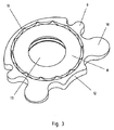
【選択図】図3An implant 1 for insertion between the vertebral bodies of the vertebral column as a space retainer instead of an intervertebral disc, vertebra, or part of a vertebra removed from the spinal column, the axis of which is to change the length of the implant 1 Free ends of the implant parts 2, 3 by means of first and second implant parts 2, 3 which are positionally shiftable relative to each other and means for being removably fixed substantially perpendicular to the axis And the connecting plates 5a and 5b connectable to each other, the connecting plates 5a and 5b have a circular or round base shape 8, and the peripheral shape of the circular or round base shape 8 is The plurality of substantially circular or round plate extensions 9, 10 are deformed so as to form a planar shape that is partially overlapped, and the plurality of plate extensions 9, 10 are different from each other. Have a diameter or Wherein they are superimposed at different overlapping degree between base shape 8 of a circular or round.
[Selection] Figure 3
Description
本発明は、脊柱から取り外された椎間板、椎骨、または椎骨の一部に代わって、スペース保持体として、脊柱の椎体の間に差し込むためのインプラントに関する The present invention relates to an implant for insertion between vertebral bodies of the spinal column as a space retainer in place of an intervertebral disc, vertebra, or part of a vertebra removed from the spinal column.
インプラントには、第1のインプラント部分と、第2のインプラント部分とが備えられ、これらのインプラント部分が、これらの共軸の長手方向軸の方向に、インプラントの長さを変化させるべく、互いに位置・姿勢をシフト可能である。 The implant includes a first implant portion and a second implant portion that are positioned relative to each other to change the length of the implant in the direction of their coaxial longitudinal axis.・ The posture can be shifted.
このようなインプラントは、例えばDE 103 11 477 A1から公知である。このようなインプラントは、実務を通じて良好なものとして確かめられており、椎体間における骨形成を、局所的に存在する状況に個々に合わせて、それぞれ顕著に助けるという特徴を有している。この特徴は、第1及び第2のインプラント部分が、これらの共軸の長手方向軸の方向にて、位置・姿勢をシフト可能であること、及び、継ぎ付け板が、解除可能な固定手段により、少なくとも一方の自由端に取り付け可能であることによって実現されている。 Such an implant is known, for example, from DE 103 11 477 A1. Such implants have been proven good through practice and have the characteristic of significantly assisting bone formation between vertebral bodies, individually tailored to the local conditions. This feature is that the first and second implant parts are shiftable in position and orientation in the direction of the longitudinal axis of their co-axes, and the connecting plate is fixed by a releasable fixing means. This is realized by being attachable to at least one free end.
良好なものとして確かめられている上記のインプラントについて、脊柱に極限的な荷重が加わる条件のためのものへとさらに改良すべく努力する中、本出願人は、インプラントの継ぎ付け板と、椎体のベースプレート、ないし、椎体のカバープレートとの間で生じる相互作用について調べた。この際、椎体のベースプレート、ないし、椎体のカバープレートの耐荷重性についての特別な依存性を確かめることができた。 In an effort to further improve the above-mentioned implants, which have been confirmed as being good, to conditions for extreme loads on the spinal column, the Applicant has determined that the implant's joint plate, vertebral body, The interaction between the base plate and the vertebral body cover plate was examined. At this time, it was possible to confirm the special dependence on the load resistance of the base plate of the vertebral body or the cover plate of the vertebral body.
本発明の根底をなす課題は、導入部で述べたインプラントについて、極限荷重条件のインプラントに用いても、椎体に対して、より良好な保護を得ることができるような具合に構成することにある。 The problem that forms the basis of the present invention is to configure the implant described in the introduction section so that better protection can be obtained for the vertebral body even if it is used for an implant under an extreme load condition. is there.
上記課題は、導入部で述べたインプラントにおいて、以下のようであることにより解決される。継ぎ付け板が円形または丸形のベース形状を有し、この円形または丸形のベース形状は、周面が、実質上円形または丸形の複数の板延長部(建て増し部)により変形されており、この複数の板延長部は、相異なる径、及び/または、円形または丸形の基本形状に対する相異なる重なり度合い(すなわち相異なる径、及び、相異なる重なり度合いの少なくとも一方)を有するということにより解決される。 The above-described problem is solved by the following in the implant described in the introduction section. The connecting plate has a circular or round base shape, and the circular or round base shape has a peripheral surface deformed by a plurality of plate extensions (built-up portions) that are substantially circular or round. The plurality of plate extensions have different diameters and / or different degrees of overlap (i.e., different diameters and / or different degrees of overlap) with respect to a circular or round basic shape. Solved.
このようなインプラントは、以下のような利点と結びついている。円形または丸形の複数の板延長部を追加することで、円形または丸形の形状により、特には、椎体のベースプレートまたはカバープレートにおける荷重印加が可能な領域に対して、局所的に、より良好な荷重の分布・割り当てを実現することができる。この際、継ぎ付け板に関する重なり度合いを不必要に増すことがなく、したがって、インプラント内への骨物質の成長を阻害することなしに実現することができる。特に、椎体のベースプレートまたはカバープレートにおける縁領域は、ベースプレートまたはカバープレートの内側領域に比べて強度が向上する。したがって、この縁領域にて椎体に対する比較的強い荷重を受けても、より温和なものとなる。 Such implants are associated with the following advantages. By adding a plurality of circular or round plate extensions, the circular or round shape makes it more locally, especially for areas of the vertebral body base plate or cover plate where load can be applied. Good load distribution and assignment can be realized. This does not unnecessarily increase the degree of overlap with respect to the connecting plate and can thus be realized without hindering the growth of bone material in the implant. In particular, the edge region of the base plate or cover plate of the vertebral body has improved strength compared to the inner region of the base plate or cover plate. Therefore, even if a relatively strong load is applied to the vertebral body in this edge region, it becomes milder.
上記の理由から、複数の円形または丸形の板延長部は、これらのうちの一部をなす複数の円形または丸形の板延長部が、幅広のくびれ部を、前記円形または丸形のベース形状の側に備えるならば、特に好ましい。このようであると、前記縁領域での荷重の支持をさらに改善することが可能になる。 For the reasons described above, the plurality of circular or round plate extensions include a plurality of circular or round plate extensions that form part of the circular or round base extension. It is particularly preferred if it is provided on the shape side. In this case, it becomes possible to further improve the load support in the edge region.
椎体のベースプレートまたはカバープレートの形状に対するインプラントの適合性を向上させるとともに、椎体のベースプレートまたはカバープレートの圧力荷重をより温和なものとするためには、幅広のくびれ部を有する円形の板延長部は、幅広のくびれ部から端面へと向かって高さ寸法が減少するというものとすることできる。このようであると、楔状の横断面を実現することができる。 Circular plate extension with wide constriction to improve implant compatibility with vertebral body base plate or cover plate shape and to make pressure load on vertebral body base plate or cover plate more gentle The portion may be such that the height dimension decreases from the wide constricted portion toward the end surface. In such a case, a wedge-shaped cross section can be realized.
インプラントには、好ましくは、円形または丸形のベース形状に、内側リングが備えられており、実質的に円形または丸形の板延長部を重ね合わせることで、適宜に変形が加えられたた外側リングを形成している。この構成の利点は、特には、継ぎ付け板の中心にある開口部が、椎体間での骨結合の形成を促進させることにある。 The implant is preferably provided with an inner ring in a circular or round base shape, and an appropriately deformed outer by overlapping substantially circular or round plate extensions. A ring is formed. The advantage of this configuration is that, in particular, the opening in the center of the connecting plate promotes the formation of bone bonds between the vertebral bodies.
特に、円形または丸形の板延長部は、少なくとも部分的に、継ぎ付け板の周端面に沿って高さ寸法が大きくなって行くように、または、高さ寸法が小さくなって行くように設けられているならば好ましいことが知られた。このような継ぎ付け板の変形により、継ぎ付け板の面積を大きくする必要なしに、加圧面の分布・割り当てを適したものとすることができる。その結果、インプラントに対する骨結合の形成を、望ましい具合に促進することができる。 In particular, the circular or round plate extension is provided at least partially so that the height dimension increases along the peripheral end surface of the connecting plate or the height dimension decreases. It has been found to be preferred if By such deformation of the joining plate, it is possible to make the distribution and assignment of the pressing surfaces suitable without having to increase the area of the joining plate. As a result, the formation of bone bonds to the implant can be facilitated in a desired manner.
インプラントの好ましい一実施形態によると、継ぎ付け板は、その周縁に、80゜〜120゜の角度だけ延びる膨出状ベース面を有している。これに代えて、または、これに加えて、継ぎ付け板は、その周縁に、5゜〜40゜の角度だけ延びる湾入状端面を有している。インプラントにおいて、さらには、継ぎ付け板が湾入状端面の中心から膨出状ベース面の中心へ延びる対称軸線に関してミラー対称に構成されていれば合目的である。 According to a preferred embodiment of the implant, the splicing plate has a bulging base surface at its periphery that extends by an angle between 80 ° and 120 °. Alternatively or in addition, the splicing plate has a bay-like end surface extending at an angle of 5 ° to 40 ° at its periphery. In the implant, it is also appropriate if the connecting plate is configured to be mirror-symmetric with respect to an axis of symmetry extending from the center of the bay-like end surface to the center of the bulging base surface.
円形または丸形の板延長部は、膨出状ベース面から湾入状端面へ向けて高さ寸法が大きくなって行くように設けられているならば、荷重挙動に対する適合性が特に良好となる。 If the circular or round plate extension is provided so that the height dimension increases from the bulging base surface to the bayed end surface, the compatibility with the load behavior is particularly good. .
本発明は、さらに、上記の態様のいずれかによる、インプラントのための継ぎ付け板に関する。 The invention further relates to a joining plate for an implant according to any of the above aspects.
以下、本発明を、図示の実施例により詳細に説明する。 Hereinafter, the present invention will be described in detail with reference to the illustrated embodiments.
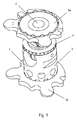
図1と図2には、不図示の脊柱の椎体の間で、脊柱から引き離された椎間板、椎骨または椎骨の一部分のためのスペース保持体として用いるインプラント1が図示されている。インプラント1は、第1のインプラント部分2と、第2のインプラント部分3とを含み、これらのインプラント部分はインプラント1の長さを変更・調整するために、これら2つのインプラント部分についての同軸の縦軸線の方向へと、互いに位置または姿勢(位置・姿勢)をシフト可能である。長さの変更は、例えば第2のインプラント部分3に割り当てられて設けられている回転可能なネジ付きリング4を通じて行うことができる。
FIGS. 1 and 2 illustrate an implant 1 used as a space holder for an intervertebral disc, a vertebra or a portion of a vertebra separated from the spine between vertebral bodies (not shown). The implant 1 comprises a first implant part 2 and a
インプラント1は、さらに、少なくとも1つ(図示の実施例では1つ)の上部継ぎ付け板5aと、1つの下部継ぎ付け板5bとを備える。これらの上部及び下部の継ぎ付け板は、両インプラント部分2,3の自由端に対し、取り外し可能に固定するための手段によって、インプラント1の縦軸線に対し実質的に垂直を向くようにして、交換可能に接続されている。ここで、上部継ぎ付け板5aと、下部継ぎ付け板5bとは、椎体のベースプレートの形状に適合させるべく、または、椎体のカバープレートの形状に適合させるべく、互いに異なる形状とすることができる。
The implant 1 further includes at least one (one in the illustrated example)
図3及び図4は、本発明による上部継ぎ付け板5aについて、上面または下面を、他から引き離した状態で示す斜視図である。上部継ぎ付け板5aは円形または丸形のベース形状8を有し、その周縁の端面は、実質上円形または丸形の第1の板延長部9および第2の板延長部10をオーバーラップさせた平面形状とすることによって変形されている。第2の板延長部10は、第1の板延長部9よりも大きな径を有し、第1の板延長部9と第2の板延長部10とは、上部継ぎ付け板5aにおける円形または丸形のベース形状8とのオーバーラップの度合いが異なっていてよい。
3 and 4 are perspective views showing the upper connecting
インプラント1は、円形または丸形のベース形状8が、開口部13を備えた内側リングを含むことができる。第1の板延長部9および第2の板延長部10の重ね合わせにより、対応して変形された外側リングが形成される。この外側リングにおいては、第2の板延長部10の外側部分が外側リングから突出している。さらに、第2の板延長部10は幅広のくびれ部を有していてよく、この幅広のくびれ部から周縁の端面へと向けて高さ寸法が小さくなっている。その結果、先端部が、外側リングから突き出す楔状の横断面をなしている。
The implant 1 can include an inner ring with a circular or round base shape 8 with an
上部継ぎ付け板5aは、周縁の端面に、80゜〜120゜の角度にわたって膨出状ベース面11を有している。膨出状ベース面11の逆側には、5゜〜40゜の角度にわたって湾入状端面12が設けられている。好ましくは、継ぎ付け板5aが、湾入状端面12の中心から膨出状ベース面の中心11へと延びる対称軸線に関しミラー対称に設けられる。特には、第1の板延長部9及び第2の板延長部10について、膨出状ベース面11から湾入状端面12へ向かって高さ寸法が増大していくように、継ぎ付け板5aの周縁部に設けることができる。
The upper connecting
1 インプラント 2 第1のインプラント部分 3 第2のインプラント部分
4 回転可能なネジ切りリング 5a 上方の継ぎ付け板
5b 下方の継ぎ付け板 6 継ぎ付け板の開口
7 椎体側の表面 8 継ぎ付け板における円形または丸形の基本形状
9 第1の円形状または丸形の延長部(建て増し部)
10 くびれ部を有する第2の円形状または丸形の延長部(建て増し部)
11 湾入状のベース面 12 膨出状の前方面 13 開口
DESCRIPTION OF SYMBOLS 1 Implant 2
5b Lower connecting plate 6 Opening of connecting plate
7 Surface on the vertebral body side 8 Basic shape of circular or round shape on the connecting
10 Second circular or round extension with constricted part (built-up part)
11 Bay-
Claims (10)
該インプラント(1)の長さを変更すべく、共軸の縦軸線の方向に互いに位置シフトが可能である第1のインプラント部分(2)及び第2のインプラント部分(3)と、
前記縦軸線に対し実質的に垂直に向けられて、取り外し可能に固定するための手段によって両インプラント部分(2,3)の少なくとも一方の自由端に接続可能な継ぎ付け板(5a,5b)とを備えたものにおいて、
継ぎ付け板(5a,5b)が円形または丸形のベース形状(8)を備えており、
該円形または丸形のベース形状(8)の周縁形状が、実質的に円形または丸形の複数の板延長部(9,10)を、部分的に重ね合わせた平面形状をなすように変形されており、前記複数の板延長部(9,10)は、互いに相異なる径を有しているか、前記円形または丸形のベース形状(8)との相異なる重ね合わせ度合いで重ね合わせられているかの少なくとも一方であることを特徴とするインプラント。 An implant (1) for insertion between the vertebral bodies of the vertebral column as a space retainer instead of an intervertebral disc, vertebrae or part of a vertebra removed from the vertebral column,
A first implant part (2) and a second implant part (3) which are positionally shiftable relative to each other in the direction of the longitudinal axis of the co-axial axis in order to change the length of the implant (1);
A joining plate (5a, 5b) oriented substantially perpendicular to said longitudinal axis and connectable to at least one free end of both implant parts (2, 3) by means for releasably securing; In those with
The connecting plate (5a, 5b) has a circular or round base shape (8),
The peripheral shape of the circular or round base shape (8) is deformed to form a planar shape in which a plurality of substantially circular or round plate extensions (9, 10) are partially overlapped. Whether the plurality of plate extensions (9, 10) have different diameters or are overlapped with each other in a different overlapping degree with the circular or round base shape (8). An implant characterized by being at least one of the following.
前記板延長部(9,10)が、膨出状ベース面(11)から湾入状端面(12)へ向けて高さ寸法が大きくなって行くように、前記周縁部に設けられていることを特徴とする請求項6に記載のインプラント(1)。 The joining plate (5a, 5b) has a bay-like end surface (12) extending over an angle of 5 ° to 40 ° at the periphery thereof,
The said board extension part (9,10) is provided in the said peripheral part so that a height dimension may become large toward a bay-like end surface (12) from a bulging base surface (11). Implant (1) according to claim 6, characterized in that
Applications Claiming Priority (1)
| Application Number | Priority Date | Filing Date | Title |
|---|---|---|---|
| PCT/DE2008/001563 WO2010031365A1 (en) | 2008-09-19 | 2008-09-19 | Implant for insertion between vertebral bodies of the spinal column |
Publications (1)
| Publication Number | Publication Date |
|---|---|
| JP2012502702A true JP2012502702A (en) | 2012-02-02 |
Family
ID=40668264
Family Applications (1)
| Application Number | Title | Priority Date | Filing Date |
|---|---|---|---|
| JP2011527200A Pending JP2012502702A (en) | 2008-09-19 | 2008-09-19 | Implants for insertion between vertebral bodies of the spine |
Country Status (5)
| Country | Link |
|---|---|
| US (1) | US20110184524A1 (en) |
| EP (1) | EP2323592A1 (en) |
| JP (1) | JP2012502702A (en) |
| TW (1) | TW201023841A (en) |
| WO (1) | WO2010031365A1 (en) |
Families Citing this family (15)
| Publication number | Priority date | Publication date | Assignee | Title |
|---|---|---|---|---|
| KR101496197B1 (en) | 2008-09-04 | 2015-02-26 | 신세스 게엠바하 | Adjustable intervertebral implant |
| US8721723B2 (en) | 2009-01-12 | 2014-05-13 | Globus Medical, Inc. | Expandable vertebral prosthesis |
| US9301850B2 (en) | 2010-04-12 | 2016-04-05 | Globus Medical, Inc. | Expandable vertebral implant |
| US8591585B2 (en) | 2010-04-12 | 2013-11-26 | Globus Medical, Inc. | Expandable vertebral implant |
| US9579211B2 (en) | 2010-04-12 | 2017-02-28 | Globus Medical, Inc. | Expandable vertebral implant |
| US8870880B2 (en) | 2010-04-12 | 2014-10-28 | Globus Medical, Inc. | Angling inserter tool for expandable vertebral implant |
| US11426287B2 (en) | 2010-04-12 | 2022-08-30 | Globus Medical Inc. | Expandable vertebral implant |
| WO2014144570A2 (en) | 2013-03-15 | 2014-09-18 | Medsmart Innovation, Inc. | Dynamic spinal segment replacement |
| US9566167B2 (en) | 2013-08-22 | 2017-02-14 | K2M, Inc. | Expandable spinal implant |
| US9211193B2 (en) | 2013-08-30 | 2015-12-15 | Aesculap Implant Systems, Llc | Prosthesis, system and method |
| US10363142B2 (en) | 2014-12-11 | 2019-07-30 | K2M, Inc. | Expandable spinal implants |
| US9775719B2 (en) | 2015-03-23 | 2017-10-03 | Musc Foundation For Research Development | Expandable vertebral body replacement device and method |
| AU2017363425B2 (en) | 2016-11-28 | 2023-06-22 | Musc Foundation For Research Development | Expandable vertebral body replacement device and method |
| US10441430B2 (en) | 2017-07-24 | 2019-10-15 | K2M, Inc. | Expandable spinal implants |
| AU2021226916A1 (en) | 2020-02-24 | 2022-10-06 | Musc Foundation For Research Development | Expandable vertebral body replacement device and method |
Citations (6)
| Publication number | Priority date | Publication date | Assignee | Title |
|---|---|---|---|---|
| JP2004275764A (en) * | 2003-03-15 | 2004-10-07 | Ulrich Gmbh & Co Kg | Implant for charging into interbody in backbone |
| WO2006116306A2 (en) * | 2005-04-26 | 2006-11-02 | Synthes (U.S.A) | Spinal implant |
| JP2006528525A (en) * | 2003-05-14 | 2006-12-21 | キリアン クラウス | Height adjustable implant for insertion between vertebral bodies and corresponding operating tools |
| US20080177387A1 (en) * | 2006-11-01 | 2008-07-24 | Warsaw Orthopedic, Inc. | Implants and Related Devices for Monitoring Bony Fusion |
| WO2008106912A1 (en) * | 2007-03-07 | 2008-09-12 | Ulrich Gmbh & Co. Kg | Intervertebral implant having an elastic component |
| JP2010521242A (en) * | 2007-03-13 | 2010-06-24 | ジンテス ゲゼルシャフト ミット ベシュレンクテル ハフツング | Adjustable intervertebral implant |
Family Cites Families (2)
| Publication number | Priority date | Publication date | Assignee | Title |
|---|---|---|---|---|
| US6296665B1 (en) * | 2000-03-20 | 2001-10-02 | Electro-Biology, Inc. | Method and apparatus for spinal fixation |
| DE202005007810U1 (en) * | 2005-05-19 | 2005-07-28 | Aesculap Ag & Co. Kg | Vertebral implant for introducing between two vertebrae comprises support plates, support elements, and a clamping device |
-
2008
- 2008-09-19 JP JP2011527200A patent/JP2012502702A/en active Pending
- 2008-09-19 WO PCT/DE2008/001563 patent/WO2010031365A1/en not_active Ceased
- 2008-09-19 EP EP08874923A patent/EP2323592A1/en not_active Withdrawn
- 2008-09-19 US US12/990,961 patent/US20110184524A1/en not_active Abandoned
-
2009
- 2009-08-05 TW TW098126303A patent/TW201023841A/en unknown
Patent Citations (8)
| Publication number | Priority date | Publication date | Assignee | Title |
|---|---|---|---|---|
| JP2004275764A (en) * | 2003-03-15 | 2004-10-07 | Ulrich Gmbh & Co Kg | Implant for charging into interbody in backbone |
| JP2006528525A (en) * | 2003-05-14 | 2006-12-21 | キリアン クラウス | Height adjustable implant for insertion between vertebral bodies and corresponding operating tools |
| WO2006116306A2 (en) * | 2005-04-26 | 2006-11-02 | Synthes (U.S.A) | Spinal implant |
| JP2008539013A (en) * | 2005-04-26 | 2008-11-13 | ジンテス ゲゼルシャフト ミット ベシュレンクテル ハフツング | Spine implant |
| US20080177387A1 (en) * | 2006-11-01 | 2008-07-24 | Warsaw Orthopedic, Inc. | Implants and Related Devices for Monitoring Bony Fusion |
| WO2008106912A1 (en) * | 2007-03-07 | 2008-09-12 | Ulrich Gmbh & Co. Kg | Intervertebral implant having an elastic component |
| JP2010519985A (en) * | 2007-03-07 | 2010-06-10 | ウルリッヒ ゲーエムベーハー・アンド・カンパニー カーゲー | Intervertebral implant with elastic part |
| JP2010521242A (en) * | 2007-03-13 | 2010-06-24 | ジンテス ゲゼルシャフト ミット ベシュレンクテル ハフツング | Adjustable intervertebral implant |
Also Published As
| Publication number | Publication date |
|---|---|
| TW201023841A (en) | 2010-07-01 |
| EP2323592A1 (en) | 2011-05-25 |
| WO2010031365A1 (en) | 2010-03-25 |
| US20110184524A1 (en) | 2011-07-28 |
Similar Documents
| Publication | Publication Date | Title |
|---|---|---|
| JP2012502702A (en) | Implants for insertion between vertebral bodies of the spine | |
| JP4471969B2 (en) | Spinal fixation device and spinal fixation device kit | |
| CN1985780B (en) | multi-wall position support | |
| JP4959345B2 (en) | Spinal intervertebral joint implant | |
| JP4119123B2 (en) | Bone screw for variable angle connection to longitudinal retainer | |
| US8147519B2 (en) | Variable angle rod connectors and the methods of use | |
| JP4731482B2 (en) | Anterior spinal instrument | |
| US7744650B2 (en) | Vertebral body replacement implant | |
| JP2672082B2 (en) | Device for holding bone parts in a desired spatial relationship | |
| JP4634055B2 (en) | Biological implants inserted between vertebral bodies of the spinal column | |
| KR101166605B1 (en) | Orthopedic spinal devices fabricated from two or more materials | |
| US7875059B2 (en) | Variable stiffness support members | |
| US20080177316A1 (en) | Apparatus and methods for spinal implant | |
| JP6343352B2 (en) | Fixing device for open wedge high tibial osteotomy | |
| JP2009523571A5 (en) | ||
| US20080262553A1 (en) | Spinal connector | |
| TWI544895B (en) | Fixation assembly for spinal vertebrae | |
| JP4551929B2 (en) | Cervical spine prosthesis | |
| EP1205152A1 (en) | Spinal column deformity correction procedure and device for putting it into practice | |
| JP2007530181A (en) | Modular intervertebral implant or modular disc prosthesis | |
| US20080200985A1 (en) | Spinal implant | |
| FR3038218A1 (en) | SACRO-ILIAC FIXING IMPLANT FOR INTERVERTEBRAL CONNECTION BAR | |
| JP2008538088A (en) | Spinal rod connector | |
| JP2007522886A (en) | Artificial intervertebral disc with universal joint | |
| JP2012504477A (en) | Surgical connector for attaching an elongated member to a bone |
Legal Events
| Date | Code | Title | Description |
|---|---|---|---|
| A977 | Report on retrieval |
Free format text: JAPANESE INTERMEDIATE CODE: A971007 Effective date: 20120927 |
|
| A131 | Notification of reasons for refusal |
Free format text: JAPANESE INTERMEDIATE CODE: A131 Effective date: 20121016 |
|
| A02 | Decision of refusal |
Free format text: JAPANESE INTERMEDIATE CODE: A02 Effective date: 20130402 |