JP2012507111A - スターター装置のための電磁スイッチ並びに該電磁スイッチの切換方法 - Google Patents
スターター装置のための電磁スイッチ並びに該電磁スイッチの切換方法 Download PDFInfo
- Publication number
- JP2012507111A JP2012507111A JP2011532666A JP2011532666A JP2012507111A JP 2012507111 A JP2012507111 A JP 2012507111A JP 2011532666 A JP2011532666 A JP 2011532666A JP 2011532666 A JP2011532666 A JP 2011532666A JP 2012507111 A JP2012507111 A JP 2012507111A
- Authority
- JP
- Japan
- Prior art keywords
- contact
- electromagnetic switch
- contact bridge
- bridge
- contacts
- Prior art date
- Legal status (The legal status is an assumption and is not a legal conclusion. Google has not performed a legal analysis and makes no representation as to the accuracy of the status listed.)
- Granted
Links
Images






Classifications
-
- H—ELECTRICITY
- H01—ELECTRIC ELEMENTS
- H01H—ELECTRIC SWITCHES; RELAYS; SELECTORS; EMERGENCY PROTECTIVE DEVICES
- H01H1/00—Contacts
- H01H1/06—Contacts characterised by the shape or structure of the contact-making surface, e.g. grooved
-
- H—ELECTRICITY
- H01—ELECTRIC ELEMENTS
- H01H—ELECTRIC SWITCHES; RELAYS; SELECTORS; EMERGENCY PROTECTIVE DEVICES
- H01H50/00—Details of electromagnetic relays
- H01H50/54—Contact arrangements
-
- F—MECHANICAL ENGINEERING; LIGHTING; HEATING; WEAPONS; BLASTING
- F02—COMBUSTION ENGINES; HOT-GAS OR COMBUSTION-PRODUCT ENGINE PLANTS
- F02N—STARTING OF COMBUSTION ENGINES; STARTING AIDS FOR SUCH ENGINES, NOT OTHERWISE PROVIDED FOR
- F02N11/00—Starting of engines by means of electric motors
- F02N11/08—Circuits specially adapted for starting of engines
- F02N11/087—Details of the switching means in starting circuits, e.g. relays or electronic switches
-
- H—ELECTRICITY
- H01—ELECTRIC ELEMENTS
- H01H—ELECTRIC SWITCHES; RELAYS; SELECTORS; EMERGENCY PROTECTIVE DEVICES
- H01H1/00—Contacts
- H01H1/12—Contacts characterised by the manner in which co-operating contacts engage
- H01H1/14—Contacts characterised by the manner in which co-operating contacts engage by abutting
- H01H1/18—Contacts characterised by the manner in which co-operating contacts engage by abutting with subsequent sliding
-
- H—ELECTRICITY
- H01—ELECTRIC ELEMENTS
- H01H—ELECTRIC SWITCHES; RELAYS; SELECTORS; EMERGENCY PROTECTIVE DEVICES
- H01H50/00—Details of electromagnetic relays
- H01H50/54—Contact arrangements
- H01H50/546—Contact arrangements for contactors having bridging contacts
-
- H—ELECTRICITY
- H01—ELECTRIC ELEMENTS
- H01H—ELECTRIC SWITCHES; RELAYS; SELECTORS; EMERGENCY PROTECTIVE DEVICES
- H01H51/00—Electromagnetic relays
- H01H51/02—Non-polarised relays
- H01H51/04—Non-polarised relays with single armature; with single set of ganged armatures
- H01H51/06—Armature is movable between two limit positions of rest and is moved in one direction due to energisation of an electromagnet and after the electromagnet is de-energised is returned by energy stored during the movement in the first direction, e.g. by using a spring, by using a permanent magnet, by gravity
- H01H51/065—Relays having a pair of normally open contacts rigidly fixed to a magnetic core movable along the axis of a solenoid, e.g. relays for starting automobiles
-
- H—ELECTRICITY
- H01—ELECTRIC ELEMENTS
- H01H—ELECTRIC SWITCHES; RELAYS; SELECTORS; EMERGENCY PROTECTIVE DEVICES
- H01H50/00—Details of electromagnetic relays
- H01H50/54—Contact arrangements
- H01H50/60—Contact arrangements moving contact being rigidly combined with movable part of magnetic circuit
Landscapes
- Physics & Mathematics (AREA)
- Electromagnetism (AREA)
- Engineering & Computer Science (AREA)
- Chemical & Material Sciences (AREA)
- Combustion & Propulsion (AREA)
- Mechanical Engineering (AREA)
- General Engineering & Computer Science (AREA)
- Contacts (AREA)
- Push-Button Switches (AREA)
- Breakers (AREA)
- Switch Cases, Indication, And Locking (AREA)
Abstract
Description
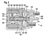
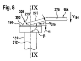
本願で提案されている解決手段によれば、コンタクトの接触面と可動コンタクトブリッジ表面との間でスクレープ動作(掻き取り動作)を2つの接触面の間で生じさせ、この動作によって汚れが除去され、他方ではスイッチング動作によっても汚れが排除される。本願請求項1における4つの代替ケース(a)〜(d)において共通していることは、電磁スイッチが2つのコンタクトを有していることである。これらのコンタクトは可動のコンタクトブリッジ(以下では可動コンタクトブリッジとも称する)によって相互に導電的に接続されている。さらにこれらの間で共通していることは、少なくとも1つのコンタクトが接触面を有していることである。第1の代替ケース(a)によれば、この接触面が少なくとも実質的に平らであり、さらに前記可動コンタクトブリッジとコンタクトとの間で電気的なコンタクトを生じさせるコンタクトブリッジ縁部が次のように配設されている。すなわち、前記接触面への当接時点から前記コンタクトと前記可動コンタクトブリッジとの間で実質的に線状の接触が可能となるように配設されている。このことは、接触状態を生じさせる2つの構成要素間で、単位面積あたりの面圧がこれまでの公知の手段よりもはるかに高くなる利点につながる。このような高い面圧を達成することは、接触面の間の質的に高い汚れ払拭作用と、前記可動コンタクトブリッジと接触面との間の可及的に良好なスクレープ作用のための前提条件となる。
Claims (18)
- スターター装置(10)のための電磁スイッチ(16)であって、
2つのコンタクト(180,181)を有しており、
前記2つのコンタクト(180,181)は、可動のコンタクトブリッジ(184)によって相互に導電的に接続される、電磁スイッチ(16)において、
前記2つのコンタクト(180,181)の少なくとも1つが、有利にはコンタクトボルト(150,151)に固定的に接続された接触面(300)を有しており、
(a)前記接触面(300)は、少なくとも実質的に平らに形成され、かつ、前記コンタクトブリッジ(184)とコンタクト(180,181)との間で電気的なコンタクトを生じさせるコンタクトブリッジ(184)縁部(279)が、前記接触面(300)への当接時点から前記コンタクト(180,181)と前記コンタクトブリッジ(184)との間で実質的に線接触が可能となるように配設されるか、又は、
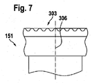
(b)前記接触面(300)は、実質的に1つの平面内に存在する複数の隆起部を有し、かつ、前記コンタクトブリッジ(184)とコンタクト(180,181)との間で電気的なコンタクトを生じさせるコンタクトブリッジ(184)縁部(279)が、前記接触面(300)への当接時点から前記コンタクト(180,181)と前記コンタクトブリッジ(184)との間で実質的に少なくとも1つの点接触が可能となるように配設されるか、又は、
(c)前記コンタクトブリッジ(184)の前記コンタクト(180,181)に向いた面(318)と、前記コンタクトボルト(150,151)の長手軸線(312)との間で、前記電磁スイッチ(16)の中心軸線(315)に対して配向される90°よりも大きい角度(β)を形成するか、又は、
(d)前記コンタクトブリッジ(184)の前記コンタクト(180,181)に向いた面(318)と、前記コンタクトボルト(150,151)の長手軸線(312)との間で、前記電磁スイッチ(16)の中心軸線(315)に対して半径方向外側へ配向される90°よりも大きい角度(β)を形成する、ことを特徴とする電磁スイッチ。 - 前記(b)の場合において、前記接触面(300)は、波形の形態を有し、この形態は有利には線状(309)または環状(310)である、請求項1記載の電磁スイッチ
- 前記(c)の場合において、前記角度(β)は、91°から105°の間の値、有利には95°である、請求項1記載の電磁スイッチ。
- 前記(d)の場合において、前記角度(β)は、91°から120°の間の値である、請求項1記載の電磁スイッチ。
- 前記縁部(279)は弓形形状又は直線状である、請求項1から4いずれか1項記載の電磁スイッチ。
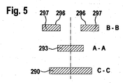
- 前記コンタクトブリッジ(184)は、切換ボルト(177)を用いて支承部に案内されており、前記コンタクトブリッジ(184)は、前記切換ボルト(177)と前記縁部(279)との間に最大断面の領域(290)を有し、さらに前記コンタクトブリッジ(184)は、前記最大断面の領域(290)と前記切換ボルト(177)との間に、低減された断面の領域(293)を有している、請求項1から5いずれか1項記載の電磁スイッチ。
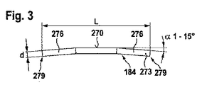
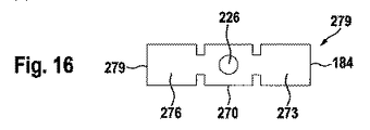
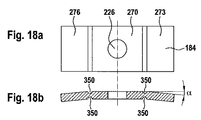
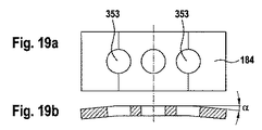
- 前記コンタクトブリッジ(184)は、切換ボルト(177)に対して直角方向に配向された面状の中央部材(270)からなり、該中央部材(270)には、前記切換ボルト(177)から離れる方向に向いた少なくとも1つの面状の外側部材(273;276)が接続しており、前記面状の中央部材(270)と前記外側部材(273;276)の間には、90°ではない角度(α)が生じている、請求項1から6いずれか1項記載の電磁スイッチ。
- 前記2つのコンタクト(180,181)のうちの少なくとも1つがコンタクトブリッジ(184)の硬度と同じかそれよりも小さい硬度を有している、請求項1から7いずれか1項記載の電磁スイッチ。
- 前記コンタクトブリッジ(184)と少なくとも1つのコンタクト(180;181)の間の摩擦値が0.1〜2の間の値、有利には0.6〜1の間の値を有している、請求項1から8いずれか1項記載の電磁スイッチ。
- 前記縁部(279)は、0.3mmよりも小さい半径を有している、請求項1から9いずれか1項記載の電磁スイッチ。
- 前記コンタクトブリッジ(184)は、有利には1mm〜4mmの間の厚み(d)を備えた薄板である、請求項1から10いずれか1項記載の電磁スイッチ。
- 前記(c)の場合において、前記コンタクト(180,181)方向に向いている、コンタクトブリッジ(184)の面が、当該コンタクト(180,181)の1つの縁部(320)に接触している、請求項1記載の電磁スイッチ。
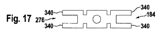
- 前記コンタクトブリッジ(184)は、各コンタクト(180,181)と複数の縁部(279)で接触している、請求項1から11いずれか1項記載の電磁スイッチ。
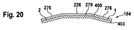
- 前記コンタクトブリッジ(184)は、複数の層からなっており、1つの層は支持体層(400)であり、該支持体層(400)の上には別のコンタクト層(403)が設けられており、前記支持体層(400)は、銅又は銀合金、鋼又は銅又は真鍮からなっており、それに対して前記コンタクト層(403)は、銅、錫、金、銀合金又は金属、酸化鉄化合物材料からなっている、請求項1から13いずれか1項記載の電磁スイッチ。
- 請求項1から14いずれか1項記載の電磁スイッチを備えていることを特徴とする、スターター装置。
- 2つのコンタクト(180,181)を有し、該2つのコンタクト(180,181)が可動のコンタクトブリッジ(184)によって接続される、電磁スイッチ、有利にはスターター装置(10)の切換方法において、
前記可動コンタクトブリッジ(184)と、前記2つのコンタクト(180,181)の少なくとも一方とのコンタクト形成の際に、前記コンタクトブリッジ(184)と前記コンタクト(180,181)接触面(300)との間でスクレープ動作が生じるようにしたことを特徴とする方法。 - 前記コンタクトブリッジ(184)の表面は縁部(279)の形態でコンタクト(180,181)の接触面(300)上を摺動するか、又は、前記コンタクト(180,181)の接触面(300)の表面は、縁部(320)の形態でコンタクトブリッジ(184)上を摺動する、請求項16記載の方法。
- 前記コンタクトブリッジ(184)と前記コンタクト(180,181)との間で部材結合が当該部材結合中の摺動応力負荷によって解除される、請求項16または17記載の方法。
Applications Claiming Priority (3)
| Application Number | Priority Date | Filing Date | Title |
|---|---|---|---|
| DE102008043186.9 | 2008-10-27 | ||
| DE102008043186A DE102008043186A1 (de) | 2008-10-27 | 2008-10-27 | Elektromagnetischer Schalter für eine Startvorrichtung sowie Verfahren zum Schalten des elektromagnetischen Schalters |
| PCT/EP2009/064153 WO2010049421A2 (de) | 2008-10-27 | 2009-10-27 | Elektromagnetischer schalter für eine startvorrichtung sowie verfahren zum schalten des elektromagnetischen schalters |
Publications (2)
| Publication Number | Publication Date |
|---|---|
| JP2012507111A true JP2012507111A (ja) | 2012-03-22 |
| JP5683472B2 JP5683472B2 (ja) | 2015-03-11 |
Family
ID=41490384
Family Applications (1)
| Application Number | Title | Priority Date | Filing Date |
|---|---|---|---|
| JP2011532666A Expired - Fee Related JP5683472B2 (ja) | 2008-10-27 | 2009-10-27 | スターター装置のための電磁スイッチ並びに該電磁スイッチの切換方法 |
Country Status (8)
| Country | Link |
|---|---|
| US (1) | US8786388B2 (ja) |
| EP (1) | EP2342726B1 (ja) |
| JP (1) | JP5683472B2 (ja) |
| CN (1) | CN102265364B (ja) |
| DE (1) | DE102008043186A1 (ja) |
| ES (1) | ES2605748T3 (ja) |
| HU (1) | HUE029788T2 (ja) |
| WO (1) | WO2010049421A2 (ja) |
Families Citing this family (19)
| Publication number | Priority date | Publication date | Assignee | Title |
|---|---|---|---|---|
| DE102010027823A1 (de) * | 2010-04-15 | 2011-10-20 | Robert Bosch Gmbh | Startvorrichtung mit einem elektromagnetischen Schalter sowie Verfahren zum Schalten des elektromagnetischen Schalters |
| DE102012215344A1 (de) * | 2012-08-29 | 2014-03-06 | Robert Bosch Gmbh | Starterrelais |
| DE102012218751B4 (de) * | 2012-10-15 | 2014-09-18 | Tyco Electronics Amp Gmbh | Schalter und Verfahren zur Herstellung eines Schalters |
| JP6609096B2 (ja) * | 2014-08-07 | 2019-11-20 | 株式会社デンソー | 電磁スイッチ |
| DE102015224287B4 (de) * | 2015-12-04 | 2019-09-19 | Seg Automotive Germany Gmbh | Elektromagnetischer Schalter |
| DE102016107127B4 (de) * | 2016-01-29 | 2025-12-18 | Tdk Electronics Ag | Relais |
| US10249463B1 (en) * | 2016-03-04 | 2019-04-02 | Scientific Components Corporation | Magnetically operated electro-mechanical latching switch |
| US10890154B2 (en) * | 2016-04-26 | 2021-01-12 | Mitsubishi Electric Corporation | Electromagnetic switch device for starter |
| CN109390165A (zh) * | 2017-08-10 | 2019-02-26 | 索恩格汽车部件(中国)有限公司 | 起动机及其开关 |
| DE102017220503B3 (de) * | 2017-11-16 | 2019-01-17 | Te Connectivity Germany Gmbh | Doppelt unterbrechender Schalter |
| CN118248498A (zh) * | 2018-02-07 | 2024-06-25 | Tdk电子股份有限公司 | 用于切换电负载的切换装置 |
| DE102018109260A1 (de) * | 2018-04-18 | 2019-10-24 | Seg Automotive Germany Gmbh | Starterrelais für eine Startvorrichtung |
| CN108493017B (zh) * | 2018-05-21 | 2019-12-20 | 江苏泓光轨道设备有限公司 | 铁路道岔转辙机转换开关组 |
| US20190385804A1 (en) * | 2018-06-19 | 2019-12-19 | Ford Global Technologies, Llc | Contactor assembly and contactor transitioning method |
| DE112018008125T5 (de) * | 2018-11-09 | 2021-07-29 | Mitsubishi Electric Corporation | Elektromagnetische Schaltungseinrichtung |
| DE102019117386A1 (de) * | 2019-06-27 | 2020-12-31 | Bayerische Motoren Werke Aktiengesellschaft | Schalter zur Herstellung einer elektrisch leitenden Verbindung |
| CN212161708U (zh) * | 2020-02-26 | 2020-12-15 | 华为技术有限公司 | 触头装置及电磁开关 |
| CN211980527U (zh) * | 2020-05-29 | 2020-11-20 | 比亚迪股份有限公司 | 继电器 |
| CN112002611B (zh) * | 2020-08-19 | 2022-06-28 | 厦门理工学院 | 一种动触点推进结构及其继电器 |
Citations (6)
| Publication number | Priority date | Publication date | Assignee | Title |
|---|---|---|---|---|
| JPS53139550U (ja) * | 1977-04-11 | 1978-11-04 | ||
| JPS5486675U (ja) * | 1977-12-02 | 1979-06-19 | ||
| JPS5488563U (ja) * | 1977-12-06 | 1979-06-22 | ||
| JP2004335436A (ja) * | 2003-04-18 | 2004-11-25 | Sumitomo Electric Ind Ltd | 直流リレー |
| US20050129019A1 (en) * | 2003-11-19 | 2005-06-16 | Cheriton David R. | Tunneled security groups |
| US20050219019A1 (en) * | 2004-03-31 | 2005-10-06 | Hans Braun | Relay with self-resilient contact bridge |
Family Cites Families (30)
| Publication number | Priority date | Publication date | Assignee | Title |
|---|---|---|---|---|
| US1238667A (en) * | 1915-06-26 | 1917-08-28 | North East Electric Co | Electric-circuit controller. |
| DE323187C (de) * | 1919-02-26 | 1920-07-17 | Ernst Doerffel Dr Ing | Elastische Kontaktbuerste fuer elektrische Maximalschalter |
| US1563670A (en) * | 1924-06-10 | 1925-12-01 | Leon C Spencer | Electromagnetically-operated starter switch |
| US1803908A (en) * | 1928-10-23 | 1931-05-05 | Eclipse Machine Co | Switch mechanism |
| DE1003318B (de) * | 1955-04-23 | 1957-02-28 | Maecker Elan Schaltelemente | Schubschalter |
| US3272949A (en) * | 1964-08-14 | 1966-09-13 | Allen Bradley Co | Bifurcated parallel contacts for relay |
| JPS5936727B2 (ja) | 1977-05-12 | 1984-09-05 | 住友電気工業株式会社 | 電極付き誘電体導波路およびその製造方法 |
| JPS5486675A (en) | 1977-12-22 | 1979-07-10 | Matsushita Electric Industrial Co Ltd | Steam heating apparatus |
| JPS5488563A (en) | 1977-12-26 | 1979-07-13 | Toppan Moore Kk | Device for sectionnprocessing form paper |
| DE3233858A1 (de) * | 1982-09-11 | 1984-03-15 | Elan-Schaltelemente Kurt Maecker Gmbh, 4040 Neuss | Schaltelement |
| JPH0736313B2 (ja) * | 1985-02-14 | 1995-04-19 | 株式会社東芝 | 電気接点 |
| DE3627459A1 (de) * | 1986-06-30 | 1988-01-14 | Schunk Metall & Kunststoff | Schaltelement fuer befehlsgeraete fuer den frontplatteneinbau |
| DE3632469A1 (de) * | 1986-09-24 | 1988-03-31 | Bosch Gmbh Robert | Elektromagnetischer schalter, insbesondere fuer andrehvorrichtungen von brennkraftmaschinen |
| DE3717031A1 (de) | 1987-05-21 | 1988-12-15 | Asea Brown Boveri | Elektrisches schaltgeraet |
| US5021760A (en) | 1989-10-03 | 1991-06-04 | Clum Manufacturing Company, Inc. | Solenoid switch contact and mounting assembly |
| DE4117242C1 (ja) * | 1991-05-27 | 1992-07-16 | Robert Bosch Gmbh, 7000 Stuttgart, De | |
| JP2740708B2 (ja) * | 1992-05-06 | 1998-04-15 | 株式会社ミツバ | スタータ用マグネットスイッチの接点体及びその製造方法 |
| FR2697370B1 (fr) * | 1992-10-26 | 1994-12-02 | Valeo Equip Electr Moteur | Contacteur pour démarreur de moteur à combustion interne de véhicules automobiles. |
| DE4301056A1 (de) * | 1993-01-16 | 1994-07-21 | Bosch Gmbh Robert | Elektromagnetischer Schalter, insbesondere Einrückrelais für den Starter einer Brennkraftmaschine |
| FR2735186B1 (fr) * | 1995-06-12 | 1997-07-18 | Valeo Equip Electr Moteur | Demarreur muni d'un contacteur comportant des moyens perfectionnes de mise a la masse electrique en position de repos et contacteur muni de tels moyens. |
| FR2741996B1 (fr) * | 1995-12-05 | 1997-12-26 | Valeo Equip Electr Moteur | Contacteur de demarreur muni d'une butee de contact mobile realisee par deformation et demarreur muni d'un tel contacteur |
| DE19549179B4 (de) | 1995-12-30 | 2005-10-27 | Robert Bosch Gmbh | Einrückrelais für eine Andrehvorrichtung |
| US6180899B1 (en) | 1999-01-04 | 2001-01-30 | Siemens Energy & Automation, Inc. | Semi-bifurcated electrical contacts |
| FR2861891B1 (fr) | 2003-10-31 | 2006-01-27 | Valeo Equip Electr Moteur | Dispositif de contacts d'un contacteur pour demarreur electrique |
| EP1577919B1 (en) * | 2004-03-15 | 2014-09-10 | Omron Corporation | Electromagnetic relay |
| DE102004017159A1 (de) | 2004-03-31 | 2005-10-20 | Bosch Gmbh Robert | Startrelais koaxial in der Starterhauptstromleitung |
| US7843289B1 (en) * | 2005-08-19 | 2010-11-30 | Scientific Components Corporation | High reliability microwave mechanical switch |
| DE202007012098U1 (de) * | 2007-08-29 | 2008-01-03 | Robert Bosch Gmbh | Startvorrichtung |
| WO2011108568A1 (ja) | 2010-03-05 | 2011-09-09 | テルモ株式会社 | カテーテル |
| JP5488563B2 (ja) | 2011-10-21 | 2014-05-14 | カシオ計算機株式会社 | 光源装置及びプロジェクタ |
-
2008
- 2008-10-27 DE DE102008043186A patent/DE102008043186A1/de not_active Withdrawn
-
2009
- 2009-10-27 HU HUE09744383A patent/HUE029788T2/hu unknown
- 2009-10-27 US US13/126,298 patent/US8786388B2/en active Active
- 2009-10-27 ES ES09744383.2T patent/ES2605748T3/es active Active
- 2009-10-27 JP JP2011532666A patent/JP5683472B2/ja not_active Expired - Fee Related
- 2009-10-27 WO PCT/EP2009/064153 patent/WO2010049421A2/de not_active Ceased
- 2009-10-27 EP EP09744383.2A patent/EP2342726B1/de active Active
- 2009-10-27 CN CN200980152621.9A patent/CN102265364B/zh active Active
Patent Citations (6)
| Publication number | Priority date | Publication date | Assignee | Title |
|---|---|---|---|---|
| JPS53139550U (ja) * | 1977-04-11 | 1978-11-04 | ||
| JPS5486675U (ja) * | 1977-12-02 | 1979-06-19 | ||
| JPS5488563U (ja) * | 1977-12-06 | 1979-06-22 | ||
| JP2004335436A (ja) * | 2003-04-18 | 2004-11-25 | Sumitomo Electric Ind Ltd | 直流リレー |
| US20050129019A1 (en) * | 2003-11-19 | 2005-06-16 | Cheriton David R. | Tunneled security groups |
| US20050219019A1 (en) * | 2004-03-31 | 2005-10-06 | Hans Braun | Relay with self-resilient contact bridge |
Also Published As
| Publication number | Publication date |
|---|---|
| HUE029788T2 (hu) | 2017-04-28 |
| US8786388B2 (en) | 2014-07-22 |
| CN102265364A (zh) | 2011-11-30 |
| ES2605748T3 (es) | 2017-03-16 |
| WO2010049421A3 (de) | 2010-06-24 |
| US20110279202A1 (en) | 2011-11-17 |
| JP5683472B2 (ja) | 2015-03-11 |
| DE102008043186A1 (de) | 2010-04-29 |
| EP2342726B1 (de) | 2016-08-31 |
| CN102265364B (zh) | 2014-12-10 |
| EP2342726A2 (de) | 2011-07-13 |
| WO2010049421A2 (de) | 2010-05-06 |
Similar Documents
| Publication | Publication Date | Title |
|---|---|---|
| JP5683472B2 (ja) | スターター装置のための電磁スイッチ並びに該電磁スイッチの切換方法 | |
| EP2241748B1 (en) | A starting device for engines | |
| KR100512942B1 (ko) | 스타터용 마그네틱 스위치 | |
| JP4124091B2 (ja) | スタータ | |
| US20150300310A1 (en) | Friction starter drive unit for meshing with a starter ring gear of a heat engine, and corresponding heat engine starter | |
| JP5350030B2 (ja) | エンジン始動装置 | |
| JP3885640B2 (ja) | スタータ用マグネットスイッチ | |
| US20080196544A1 (en) | Starter having excessive-torque-absorbing device | |
| CN107068490B (zh) | 一种起动机用电磁开关及其起动机 | |
| CN102667137B (zh) | 噪声优化的起动装置 | |
| JP2005285467A (ja) | 回転電機および自動車用スタータ | |
| JP2017504750A (ja) | 改良された突出極インダクタを有する回転電機が設けられた自動車両の熱機関用スタータ、および対応する極片 | |
| CN102800529A (zh) | 起动装置 | |
| KR20010006638A (ko) | 스타터 | |
| RU2541345C1 (ru) | Стартер для двигателя внутреннего сгорания | |
| JP2012044842A (ja) | スタータ | |
| JP2006307680A (ja) | スタータ | |
| CN103081316A (zh) | 换向器电动机 | |
| CN223527092U (zh) | 降低单向器啮合速度的电磁开关 | |
| JP3335376B2 (ja) | スタータ | |
| CN217159433U (zh) | 电驱动器及其电刷 | |
| CN210692448U (zh) | 一种防打齿电磁开关防护结构 | |
| CN111627757B (zh) | 一种电磁开关及具有该电磁开关的软啮合起动机 | |
| JP2013130077A (ja) | スタータ | |
| EP2559046B1 (de) | Startvorrichtung mit einem elektromagnetischen schalter sowie verfahren zum schalten des elektromagnetischen schalters |
Legal Events
| Date | Code | Title | Description |
|---|---|---|---|
| A977 | Report on retrieval |
Free format text: JAPANESE INTERMEDIATE CODE: A971007 Effective date: 20121217 |
|
| A131 | Notification of reasons for refusal |
Free format text: JAPANESE INTERMEDIATE CODE: A131 Effective date: 20121221 |
|
| A601 | Written request for extension of time |
Free format text: JAPANESE INTERMEDIATE CODE: A601 Effective date: 20130321 |
|
| A602 | Written permission of extension of time |
Free format text: JAPANESE INTERMEDIATE CODE: A602 Effective date: 20130328 |
|
| A521 | Request for written amendment filed |
Free format text: JAPANESE INTERMEDIATE CODE: A523 Effective date: 20130405 |
|
| A131 | Notification of reasons for refusal |
Free format text: JAPANESE INTERMEDIATE CODE: A131 Effective date: 20130430 |
|
| A601 | Written request for extension of time |
Free format text: JAPANESE INTERMEDIATE CODE: A601 Effective date: 20130730 |
|
| A602 | Written permission of extension of time |
Free format text: JAPANESE INTERMEDIATE CODE: A602 Effective date: 20130806 |
|
| A131 | Notification of reasons for refusal |
Free format text: JAPANESE INTERMEDIATE CODE: A131 Effective date: 20131125 |
|
| A601 | Written request for extension of time |
Free format text: JAPANESE INTERMEDIATE CODE: A601 Effective date: 20140224 |
|
| A602 | Written permission of extension of time |
Free format text: JAPANESE INTERMEDIATE CODE: A602 Effective date: 20140303 |
|
| A521 | Request for written amendment filed |
Free format text: JAPANESE INTERMEDIATE CODE: A523 Effective date: 20140522 |
|
| A02 | Decision of refusal |
Free format text: JAPANESE INTERMEDIATE CODE: A02 Effective date: 20140630 |
|
| A521 | Request for written amendment filed |
Free format text: JAPANESE INTERMEDIATE CODE: A523 Effective date: 20141021 |
|
| A911 | Transfer to examiner for re-examination before appeal (zenchi) |
Free format text: JAPANESE INTERMEDIATE CODE: A911 Effective date: 20141029 |
|
| TRDD | Decision of grant or rejection written | ||
| A01 | Written decision to grant a patent or to grant a registration (utility model) |
Free format text: JAPANESE INTERMEDIATE CODE: A01 Effective date: 20141215 |
|
| A61 | First payment of annual fees (during grant procedure) |
Free format text: JAPANESE INTERMEDIATE CODE: A61 Effective date: 20150113 |
|
| R150 | Certificate of patent or registration of utility model |
Ref document number: 5683472 Country of ref document: JP Free format text: JAPANESE INTERMEDIATE CODE: R150 |
|
| S111 | Request for change of ownership or part of ownership |
Free format text: JAPANESE INTERMEDIATE CODE: R313113 |
|
| R350 | Written notification of registration of transfer |
Free format text: JAPANESE INTERMEDIATE CODE: R350 |
|
| R250 | Receipt of annual fees |
Free format text: JAPANESE INTERMEDIATE CODE: R250 |
|
| R250 | Receipt of annual fees |
Free format text: JAPANESE INTERMEDIATE CODE: R250 |
|
| R250 | Receipt of annual fees |
Free format text: JAPANESE INTERMEDIATE CODE: R250 |
|
| R250 | Receipt of annual fees |
Free format text: JAPANESE INTERMEDIATE CODE: R250 |
|
| R250 | Receipt of annual fees |
Free format text: JAPANESE INTERMEDIATE CODE: R250 |
|
| R250 | Receipt of annual fees |
Free format text: JAPANESE INTERMEDIATE CODE: R250 |
|
| LAPS | Cancellation because of no payment of annual fees |