JP2013017338A - Hブリッジ駆動回路 - Google Patents
Hブリッジ駆動回路 Download PDFInfo
- Publication number
- JP2013017338A JP2013017338A JP2011149584A JP2011149584A JP2013017338A JP 2013017338 A JP2013017338 A JP 2013017338A JP 2011149584 A JP2011149584 A JP 2011149584A JP 2011149584 A JP2011149584 A JP 2011149584A JP 2013017338 A JP2013017338 A JP 2013017338A
- Authority
- JP
- Japan
- Prior art keywords
- voltage
- control
- arm
- transistor
- output
- Prior art date
- Legal status (The legal status is an assumption and is not a legal conclusion. Google has not performed a legal analysis and makes no representation as to the accuracy of the status listed.)
- Granted
Links
- KPGCIKDEXQALKK-UHFFFAOYSA-N 2-(4-azido-2-nitroanilino)ethyl phosphono hydrogen phosphate Chemical compound OP(O)(=O)OP(O)(=O)OCCNC1=CC=C(N=[N+]=[N-])C=C1[N+]([O-])=O KPGCIKDEXQALKK-UHFFFAOYSA-N 0.000 description 5
- 238000000034 method Methods 0.000 description 4
- 230000007704 transition Effects 0.000 description 2
- XJLXINKUBYWONI-NNYOXOHSSA-O NADP(+) Chemical compound NC(=O)C1=CC=C[N+]([C@H]2[C@@H]([C@H](O)[C@@H](COP(O)(=O)OP(O)(=O)OC[C@@H]3[C@H]([C@@H](OP(O)(O)=O)[C@@H](O3)N3C4=NC=NC(N)=C4N=C3)O)O2)O)=C1 XJLXINKUBYWONI-NNYOXOHSSA-O 0.000 description 1
- 238000010586 diagram Methods 0.000 description 1
- 230000002093 peripheral effect Effects 0.000 description 1
- 239000004065 semiconductor Substances 0.000 description 1
Images

Classifications
-
- H—ELECTRICITY
- H02—GENERATION; CONVERSION OR DISTRIBUTION OF ELECTRIC POWER
- H02M—APPARATUS FOR CONVERSION BETWEEN AC AND AC, BETWEEN AC AND DC, OR BETWEEN DC AND DC, AND FOR USE WITH MAINS OR SIMILAR POWER SUPPLY SYSTEMS; CONVERSION OF DC OR AC INPUT POWER INTO SURGE OUTPUT POWER; CONTROL OR REGULATION THEREOF
- H02M7/00—Conversion of AC power input into DC power output; Conversion of DC power input into AC power output
- H02M7/42—Conversion of DC power input into AC power output without possibility of reversal
- H02M7/44—Conversion of DC power input into AC power output without possibility of reversal by static converters
- H02M7/48—Conversion of DC power input into AC power output without possibility of reversal by static converters using discharge tubes with control electrode or semiconductor devices with control electrode
-
- H—ELECTRICITY
- H02—GENERATION; CONVERSION OR DISTRIBUTION OF ELECTRIC POWER
- H02P—CONTROL OR REGULATION OF ELECTRIC MOTORS, ELECTRIC GENERATORS OR DYNAMO-ELECTRIC CONVERTERS; CONTROLLING TRANSFORMERS, REACTORS OR CHOKE COILS
- H02P25/00—Arrangements or methods for the control of AC motors characterised by the kind of AC motor or by structural details
- H02P25/02—Arrangements or methods for the control of AC motors characterised by the kind of AC motor or by structural details characterised by the kind of motor
- H02P25/032—Reciprocating, oscillating or vibrating motors
- H02P25/034—Voice coil motors
-
- H—ELECTRICITY
- H02—GENERATION; CONVERSION OR DISTRIBUTION OF ELECTRIC POWER
- H02P—CONTROL OR REGULATION OF ELECTRIC MOTORS, ELECTRIC GENERATORS OR DYNAMO-ELECTRIC CONVERTERS; CONTROLLING TRANSFORMERS, REACTORS OR CHOKE COILS
- H02P7/00—Arrangements for regulating or controlling the speed or torque of electric DC motors
- H02P7/06—Arrangements for regulating or controlling the speed or torque of electric DC motors for regulating or controlling an individual DC dynamo-electric motor by varying field or armature current
- H02P7/18—Arrangements for regulating or controlling the speed or torque of electric DC motors for regulating or controlling an individual DC dynamo-electric motor by varying field or armature current by master control with auxiliary power
- H02P7/24—Arrangements for regulating or controlling the speed or torque of electric DC motors for regulating or controlling an individual DC dynamo-electric motor by varying field or armature current by master control with auxiliary power using discharge tubes or semiconductor devices
- H02P7/28—Arrangements for regulating or controlling the speed or torque of electric DC motors for regulating or controlling an individual DC dynamo-electric motor by varying field or armature current by master control with auxiliary power using discharge tubes or semiconductor devices using semiconductor devices
-
- H—ELECTRICITY
- H02—GENERATION; CONVERSION OR DISTRIBUTION OF ELECTRIC POWER
- H02M—APPARATUS FOR CONVERSION BETWEEN AC AND AC, BETWEEN AC AND DC, OR BETWEEN DC AND DC, AND FOR USE WITH MAINS OR SIMILAR POWER SUPPLY SYSTEMS; CONVERSION OF DC OR AC INPUT POWER INTO SURGE OUTPUT POWER; CONTROL OR REGULATION THEREOF
- H02M7/00—Conversion of AC power input into DC power output; Conversion of DC power input into AC power output
- H02M7/42—Conversion of DC power input into AC power output without possibility of reversal
- H02M7/44—Conversion of DC power input into AC power output without possibility of reversal by static converters
- H02M7/48—Conversion of DC power input into AC power output without possibility of reversal by static converters using discharge tubes with control electrode or semiconductor devices with control electrode
- H02M7/53—Conversion of DC power input into AC power output without possibility of reversal by static converters using discharge tubes with control electrode or semiconductor devices with control electrode using devices of a triode or transistor type requiring continuous application of a control signal
- H02M7/537—Conversion of DC power input into AC power output without possibility of reversal by static converters using discharge tubes with control electrode or semiconductor devices with control electrode using devices of a triode or transistor type requiring continuous application of a control signal using semiconductor devices only, e.g. single switched pulse inverters
- H02M7/5387—Conversion of DC power input into AC power output without possibility of reversal by static converters using discharge tubes with control electrode or semiconductor devices with control electrode using devices of a triode or transistor type requiring continuous application of a control signal using semiconductor devices only, e.g. single switched pulse inverters in a bridge configuration
Landscapes
- Engineering & Computer Science (AREA)
- Power Engineering (AREA)
- Control Of Direct Current Motors (AREA)
- Electronic Switches (AREA)
- Amplifiers (AREA)
- Dc-Dc Converters (AREA)
- Inverter Devices (AREA)
Abstract
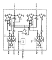
【解決手段】直列接続された上側トランジスタQP1、QP2と下側トランジスタQN1、QN2からなるアームを2つ有し、両アームにおける上側および下側トランジスタの接続点を一対の出力端として、ここに接続されるコイルに順方向および逆方向の電流を供給するHブリッジ駆動回路であって、ハイインピーダンス回路10−1、10−2の出力により、出力トランジスタQP1,QP2をオンオフするPWMモードと、オペアンプOPの出力により、出力端OUT1、OUT2の電圧を制御する定電圧モードを有し、切り換え信号STBBによってこれを切り換える。
【選択図】図1
Description
このような回路において、切り換え信号STBB=Hである、定電圧駆動モードであれば、DACおよびOPは動作する。そして、IN1P,IN1N,IN2P,IN2NがいずれもLまたはHの場合には、インピーダンス制御回路10−1,10−2の出力はP側H、N側Hとなる。従って、スイッチSW3−1,SW3−2のいずれもオンであり、トランジスタQP1,QP2のいずれもオフとなり、一方トランジスタQN1,QN2のゲートはLであり、これらもオフとなる。従って、出力端OUT1,OUT2の出力はハイインピース状態(Hiz)となる。

一方、切り換え信号STBB=Lである、PWMモードでは、DACおよびOPはその動作が停止され、OPの出力端はグランドに接続される。
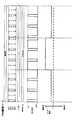
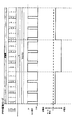
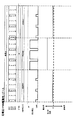
図4には、PWMモードの場合において、トランジスタQP1、QP2をオンの際に定電圧制御する例が示してある。すなわち、切り換え信号STBB=Lの状態においても、DACおよびOPを動作させ、出力端OUT1、OUT2の上側電圧をVoutに定電圧制御する。すなわち、インピーダンス制御回路10−1,10−2からのP側出力がLの際にスイッチSW1−1、1−2をオンとして、OPの出力をトランジスタQP1、QP2のゲートに供給して、出力端OUT1,OUT2の電圧をOPによりVoutに制御する。
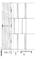
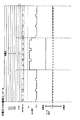
図5には、定電流モードにおいて、さらにPWM駆動を利用する場合を示す。すなわち、定電圧モードにおいて、入力してくる制御電圧データHBPWをPWM制御によって変更する。これによって、制御電圧データのビット数を増やさなくても、よりきめ細かい出力電圧制御を行うことができる。
このような回路において、切り換え信号STBB=Hである、定電圧駆動モードであれば、DACおよびOPは動作する。そして、IN1P,IN1N,IN2P,IN2NがいずれもLまたはHの場合には、ハイインピーダンス制御回路10−1,10−2の出力はP側H、N側Hとなる。従って、スイッチSW3−1,SW3−2のいずれもオンであり、トランジスタQP1,QP2のいずれもオフとなり、一方トランジスタQN1,QN2のゲートはLであり、これらもオフとなる。従って、出力端OUT1,OUT2の出力はハイインピース状態(Hiz)となる。
図4には、PWMモードの場合において、トランジスタQP1、QP2をオンの際に定電圧制御する例が示してある。すなわち、切り換え信号STBB=Lの状態においても、DACおよびOPを動作させ、出力端OUT1、OUT2の上側電圧をVoutに定電圧制御する。すなわち、ハイインピーダンス制御回路10−1,10−2からのP側出力がLの際にスイッチSW1−1、SW1−2をオンとして、OPの出力をトランジスタQP1、QP2のゲートに供給して、出力端OUT1,OUT2の電圧をOPによりVoutに制御する。
図5には、定電圧モードにおいて、さらにPWM駆動を利用する場合を示す。すなわち、定電圧モードにおいて、入力してくる制御電圧データHBPWをPWM制御によって変更する。これによって、制御電圧データのビット数を増やさなくても、よりきめ細かい出力電圧制御を行うことができる。
Claims (3)
- 直列接続された上側トランジスタと下側トランジスタからなるアームを2つ有し、両アームにおける上側および下側トランジスタの接続点を一対の出力端として、ここに接続されるコイルに順方向および逆方向の電流を供給するHブリッジ駆動回路であって、
第1アームおよび第2アームの上側トランジスタの制御端に所定のデューティー比のPWM信号を供給することで、第1アームの下側トランジスタをオンした状態で、第2アームの上側トランジスタをPWM信号によりオンオフする工程と、第2アームの下側トランジスタをオンした状態で、第1アームの上側トランジスタをPWM制御によりオンオフする工程とを繰り返すPWMモードと、
1入力端に制御電圧が入力されるオペアンプの出力端を両アームの上側トランジスタの制御端に接続し、前記一対の出力端をオペアンプの他入力端に帰還することで、出力端の電圧を制御電圧に制御することで、第1アームの下側トランジスタをオンした状態で、第2アームの上側トランジスタの制御端電圧を制御することにより出力端の電圧を制御電圧に制御する工程と、第2アームの下側トランジスタをオンした状態で、第1アームの上側トランジスタ制御端電圧を制御することにより出力端の電圧を制御電圧に制御する工程とを繰り返す定電圧モードと、
を有し、
外部からの切り換え信号に応じて前記両モードを切り換えるHブリッジ駆動回路。 - 請求項1に記載のHブリッジ駆動回路において、
前記PWMモードにおいて、
さらに、出力端の電圧を定電圧制御するHブリッジ駆動回路。 - 請求項1に記載のHブリッジ駆動回路において、
前記定電圧モードにおいて、
さらに、前記オペアンプに入力する制御電圧を所定のデューティー比のPWM信号とするHブリッジ駆動回路。
Priority Applications (5)
| Application Number | Priority Date | Filing Date | Title |
|---|---|---|---|
| JP2011149584A JP5908224B2 (ja) | 2011-07-05 | 2011-07-05 | Hブリッジ駆動回路 |
| US13/533,638 US8456219B2 (en) | 2011-07-05 | 2012-06-26 | H bridge driver circuit |
| TW101122948A TW201310890A (zh) | 2011-07-05 | 2012-06-27 | H電橋驅動電路 |
| KR1020120072654A KR101300901B1 (ko) | 2011-07-05 | 2012-07-04 | H 브리지 구동 회로 |
| CN201210233133.4A CN102868356B (zh) | 2011-07-05 | 2012-07-05 | H桥驱动电路 |
Applications Claiming Priority (1)
| Application Number | Priority Date | Filing Date | Title |
|---|---|---|---|
| JP2011149584A JP5908224B2 (ja) | 2011-07-05 | 2011-07-05 | Hブリッジ駆動回路 |
Publications (2)
| Publication Number | Publication Date |
|---|---|
| JP2013017338A true JP2013017338A (ja) | 2013-01-24 |
| JP5908224B2 JP5908224B2 (ja) | 2016-04-26 |
Family
ID=47438294
Family Applications (1)
| Application Number | Title | Priority Date | Filing Date |
|---|---|---|---|
| JP2011149584A Active JP5908224B2 (ja) | 2011-07-05 | 2011-07-05 | Hブリッジ駆動回路 |
Country Status (5)
| Country | Link |
|---|---|
| US (1) | US8456219B2 (ja) |
| JP (1) | JP5908224B2 (ja) |
| KR (1) | KR101300901B1 (ja) |
| CN (1) | CN102868356B (ja) |
| TW (1) | TW201310890A (ja) |
Cited By (1)
| Publication number | Priority date | Publication date | Assignee | Title |
|---|---|---|---|---|
| JP2016129873A (ja) * | 2015-01-14 | 2016-07-21 | 三菱電機株式会社 | ペルチェ素子駆動装置、ペルチェ素子駆動方法 |
Families Citing this family (7)
| Publication number | Priority date | Publication date | Assignee | Title |
|---|---|---|---|---|
| CN103501144B (zh) * | 2013-09-18 | 2016-04-20 | 宁波杜亚机电技术有限公司 | 电机的速度控制方法 |
| FR3047619B1 (fr) * | 2016-02-08 | 2019-04-19 | Continental Automotive France | Dispositif et procede de commutation symetrique de charge dans un pont en h |
| KR102586067B1 (ko) * | 2016-02-11 | 2023-10-05 | 삼성전기주식회사 | 모터 드라이버 및 이를 갖는 카메라 모듈 |
| CN106211159B (zh) * | 2016-07-29 | 2019-12-27 | 北京小米移动软件有限公司 | 基于蓝牙的身份识别方法及装置 |
| FR3056039B1 (fr) * | 2016-09-14 | 2018-09-28 | Continental Automotive France | Procede d'alimentation d'une charge inductive |
| TWI768526B (zh) * | 2020-10-30 | 2022-06-21 | 茂達電子股份有限公司 | 三相馬達驅動電路及方法 |
| KR20220115117A (ko) | 2021-02-08 | 2022-08-17 | 이수빈 | 실내 환기구 설치구조 |
Citations (5)
| Publication number | Priority date | Publication date | Assignee | Title |
|---|---|---|---|---|
| JPH07170785A (ja) * | 1993-12-10 | 1995-07-04 | Canon Inc | モータ駆動装置 |
| JPH10190370A (ja) * | 1996-12-26 | 1998-07-21 | Nippon Inter Electronics Corp | 電力増幅器 |
| JPH10271889A (ja) * | 1997-03-28 | 1998-10-09 | Komatsu Ltd | 電動式パワーステアリング制御装置 |
| JP2005094460A (ja) * | 2003-09-18 | 2005-04-07 | Yaskawa Electric Corp | サーボ増幅器 |
| JP2007336789A (ja) * | 2006-06-19 | 2007-12-27 | Sumitomo Heavy Ind Ltd | モータ駆動装置 |
Family Cites Families (11)
| Publication number | Priority date | Publication date | Assignee | Title |
|---|---|---|---|---|
| US5257175A (en) * | 1992-05-08 | 1993-10-26 | Texas Instruments Incorporated | Analog control of inductive flyback voltages in a full bridge circuit |
| KR20050119687A (ko) * | 2003-04-07 | 2005-12-21 | 코닌클리즈케 필립스 일렉트로닉스 엔.브이. | 디지털 증폭기, 리플 억제 회로 및 리플 억제 방법 |
| US6989955B2 (en) * | 2004-05-28 | 2006-01-24 | Texas Instruments Incorporated | Efficient transition from class D to linear operation in dual-mode voice coil motor controllers |
| JP4658786B2 (ja) * | 2005-11-30 | 2011-03-23 | 株式会社日立製作所 | 電源装置 |
| US7142436B1 (en) * | 2006-01-25 | 2006-11-28 | Wise Life Technology Co., Ltd. | Reliable bi-directional driving circuit for wide supply voltage and output range |
| US7477082B2 (en) * | 2007-05-15 | 2009-01-13 | Freescale Semiconductor, Inc. | Method and circuit for driving H-bridge that reduces switching noise |
| JP2008289225A (ja) | 2007-05-15 | 2008-11-27 | Sanyo Electric Co Ltd | モータ駆動回路 |
| CN101447733A (zh) * | 2007-12-26 | 2009-06-03 | 程杰保 | 高效率线性直流稳定电源 |
| JP5337533B2 (ja) | 2009-02-27 | 2013-11-06 | セミコンダクター・コンポーネンツ・インダストリーズ・リミテッド・ライアビリティ・カンパニー | モータ駆動回路 |
| TWI394362B (zh) * | 2009-09-11 | 2013-04-21 | Anpec Electronics Corp | 驅動直流馬達的方法及其相關電路 |
| JP5298050B2 (ja) * | 2010-03-11 | 2013-09-25 | トヨタ自動車株式会社 | スイッチング電源回路 |
-
2011
- 2011-07-05 JP JP2011149584A patent/JP5908224B2/ja active Active
-
2012
- 2012-06-26 US US13/533,638 patent/US8456219B2/en active Active
- 2012-06-27 TW TW101122948A patent/TW201310890A/zh unknown
- 2012-07-04 KR KR1020120072654A patent/KR101300901B1/ko active Active
- 2012-07-05 CN CN201210233133.4A patent/CN102868356B/zh active Active
Patent Citations (5)
| Publication number | Priority date | Publication date | Assignee | Title |
|---|---|---|---|---|
| JPH07170785A (ja) * | 1993-12-10 | 1995-07-04 | Canon Inc | モータ駆動装置 |
| JPH10190370A (ja) * | 1996-12-26 | 1998-07-21 | Nippon Inter Electronics Corp | 電力増幅器 |
| JPH10271889A (ja) * | 1997-03-28 | 1998-10-09 | Komatsu Ltd | 電動式パワーステアリング制御装置 |
| JP2005094460A (ja) * | 2003-09-18 | 2005-04-07 | Yaskawa Electric Corp | サーボ増幅器 |
| JP2007336789A (ja) * | 2006-06-19 | 2007-12-27 | Sumitomo Heavy Ind Ltd | モータ駆動装置 |
Cited By (1)
| Publication number | Priority date | Publication date | Assignee | Title |
|---|---|---|---|---|
| JP2016129873A (ja) * | 2015-01-14 | 2016-07-21 | 三菱電機株式会社 | ペルチェ素子駆動装置、ペルチェ素子駆動方法 |
Also Published As
| Publication number | Publication date |
|---|---|
| US8456219B2 (en) | 2013-06-04 |
| TW201310890A (zh) | 2013-03-01 |
| CN102868356A (zh) | 2013-01-09 |
| JP5908224B2 (ja) | 2016-04-26 |
| KR20130005236A (ko) | 2013-01-15 |
| US20130009690A1 (en) | 2013-01-10 |
| KR101300901B1 (ko) | 2013-08-27 |
| CN102868356B (zh) | 2014-12-10 |
Similar Documents
| Publication | Publication Date | Title |
|---|---|---|
| JP5908224B2 (ja) | Hブリッジ駆動回路 | |
| CN101361260B (zh) | 电机驱动电路、驱动方法、电机装置及使用了它的电子设备 | |
| JP5883603B2 (ja) | Dcdcコンバータの制御回路、及びdcdcコンバータ | |
| JP2019140432A (ja) | パワートランジスタのゲートドライバ回路、モータドライバ回路 | |
| US11792569B2 (en) | Driver circuits | |
| TW201037953A (en) | Direct current converter | |
| EP2544344A1 (en) | Triple mode charge-pump. | |
| JP2013532458A (ja) | 高耐圧反転型チャージポンプ | |
| JP4680013B2 (ja) | モータ駆動回路 | |
| JP4266811B2 (ja) | 定電圧回路 | |
| US7449948B2 (en) | Amplifier | |
| CN102195635A (zh) | 可提高稳定性的输出缓冲电路 | |
| JP2017183995A (ja) | 半導体装置、半導体システム及び半導体装置の制御方法 | |
| JP2025008261A (ja) | ゲートドライバ回路、それを用いたモータ駆動装置、電子機器 | |
| JP2006166391A (ja) | スイッチングアンプ及びスイッチングアンプの駆動方法 | |
| CN100521500C (zh) | 线圈负载驱动电路以及光盘装置 | |
| TWI334268B (en) | Class-d audio amplifier with half-swing pulse-width-modulation | |
| CN116097560A (zh) | 驱动器电路 | |
| WO2022137292A1 (ja) | Sepicコンバータの同期整流素子の駆動用電源 | |
| US11683017B2 (en) | Class-D amplifier | |
| JP4611104B2 (ja) | 発振回路およびそれを用いたスイッチング電源装置 | |
| US7502214B2 (en) | Flexible hook switch driver circuit | |
| JP2005245165A (ja) | 駆動回路およびスイッチング電源装置 | |
| JP2011135329A (ja) | 電気回路 |
Legal Events
| Date | Code | Title | Description |
|---|---|---|---|
| A621 | Written request for application examination |
Free format text: JAPANESE INTERMEDIATE CODE: A621 Effective date: 20140701 |
|
| A977 | Report on retrieval |
Free format text: JAPANESE INTERMEDIATE CODE: A971007 Effective date: 20150624 |
|
| A131 | Notification of reasons for refusal |
Free format text: JAPANESE INTERMEDIATE CODE: A131 Effective date: 20150630 |
|
| A521 | Request for written amendment filed |
Free format text: JAPANESE INTERMEDIATE CODE: A523 Effective date: 20150910 |
|
| RD02 | Notification of acceptance of power of attorney |
Free format text: JAPANESE INTERMEDIATE CODE: A7422 Effective date: 20160201 |
|
| RD04 | Notification of resignation of power of attorney |
Free format text: JAPANESE INTERMEDIATE CODE: A7424 Effective date: 20160204 |
|
| TRDD | Decision of grant or rejection written | ||
| A01 | Written decision to grant a patent or to grant a registration (utility model) |
Free format text: JAPANESE INTERMEDIATE CODE: A01 Effective date: 20160223 |
|
| A61 | First payment of annual fees (during grant procedure) |
Free format text: JAPANESE INTERMEDIATE CODE: A61 Effective date: 20160323 |
|
| R150 | Certificate of patent or registration of utility model |
Ref document number: 5908224 Country of ref document: JP Free format text: JAPANESE INTERMEDIATE CODE: R150 |
|
| R250 | Receipt of annual fees |
Free format text: JAPANESE INTERMEDIATE CODE: R250 |
|
| R250 | Receipt of annual fees |
Free format text: JAPANESE INTERMEDIATE CODE: R250 |
|
| R250 | Receipt of annual fees |
Free format text: JAPANESE INTERMEDIATE CODE: R250 |
|
| R250 | Receipt of annual fees |
Free format text: JAPANESE INTERMEDIATE CODE: R250 |
|
| R250 | Receipt of annual fees |
Free format text: JAPANESE INTERMEDIATE CODE: R250 |
|
| R250 | Receipt of annual fees |
Free format text: JAPANESE INTERMEDIATE CODE: R250 |
|
| R250 | Receipt of annual fees |
Free format text: JAPANESE INTERMEDIATE CODE: R250 |