JP2013018497A - Beverage can - Google Patents

Beverage can Download PDF

Info

Publication number
JP2013018497A
JP2013018497A JP2011151151A JP2011151151A JP2013018497A JP 2013018497 A JP2013018497 A JP 2013018497A JP 2011151151 A JP2011151151 A JP 2011151151A JP 2011151151 A JP2011151151 A JP 2011151151A JP 2013018497 A JP2013018497 A JP 2013018497A
Authority
JP
Japan
Prior art keywords
closing member
piece
edge
beverage
opening
Prior art date
Legal status (The legal status is an assumption and is not a legal conclusion. Google has not performed a legal analysis and makes no representation as to the accuracy of the status listed.)
Granted
Application number
JP2011151151A
Other languages
Japanese (ja)
Other versions
JP5901903B2 (en
Inventor
Yasushi Tashiro
泰 田代
Shinichi Kojima
真一 小島
Kazunori Ikeda
和紀 池田
Takehiro Muraoka
健裕 村岡
Tetsuo Kashiwazaki
哲夫 柏崎
Asumi Suwa
明日美 諏訪
Current Assignee (The listed assignees may be inaccurate. Google has not performed a legal analysis and makes no representation or warranty as to the accuracy of the list.)
Altemira Co Ltd
Original Assignee
Showa Aluminum Can Corp
Priority date (The priority date is an assumption and is not a legal conclusion. Google has not performed a legal analysis and makes no representation as to the accuracy of the date listed.)
Filing date
Publication date
Application filed by Showa Aluminum Can Corp filed Critical Showa Aluminum Can Corp
Priority to JP2011151151A priority Critical patent/JP5901903B2/en
Publication of JP2013018497A publication Critical patent/JP2013018497A/en
Application granted granted Critical
Publication of JP5901903B2 publication Critical patent/JP5901903B2/en
Expired - Fee Related legal-status Critical Current
Anticipated expiration legal-status Critical

Links

Images

Landscapes

  • Rigid Containers With Two Or More Constituent Elements (AREA)
  • Packages (AREA)
  • Containers Opened By Tearing Frangible Portions (AREA)

Abstract

【課題】開口を塞ぐ塞ぎ部材の離脱が起きにくい飲料缶を提供する。
【解決手段】塞ぎ部材300には、円形に形成され容器本体200の上部に形成された開口210を覆うとともに外周縁が容器本体200のカール部に接着される基部310が設けられている。また、基部310の外周縁から外側方向に突出するように設けられ塞ぎ部材300が容器本体200から剥がされる際にユーザにより把持される把持部320が設けられている。また塞ぎ部材300には、基部310の外周縁から外側方向に向かって突出するように設けられ容器本体200の外周面に対向配置されるとともにこの外周面に接着される接着部330が設けられている。
【選択図】図7
Disclosed is a beverage can in which a closing member that closes an opening does not easily come off.
A closing member (300) is provided with a base (310) that is formed in a circular shape and covers an opening (210) formed at the top of a container body (200) and whose outer peripheral edge is bonded to a curled portion of the container body (200). In addition, a grip portion 320 provided so as to protrude outward from the outer peripheral edge of the base portion 310 and gripped by the user when the closing member 300 is peeled off from the container main body 200 is provided. In addition, the closing member 300 is provided with an adhesive portion 330 that is provided so as to protrude outward from the outer peripheral edge of the base portion 310 and is opposed to the outer peripheral surface of the container body 200 and bonded to the outer peripheral surface. Yes.
[Selection] Figure 7

Description

本発明は、飲料缶に関する。   The present invention relates to a beverage can.

金属缶のフランジカール部にアルミ箔蓋が接着されたアルミ箔シール缶が提案されている(例えば、特許文献1参照)。   An aluminum foil seal can in which an aluminum foil lid is bonded to a flange curl portion of a metal can has been proposed (see, for example, Patent Document 1).

実開平1−126928号公報Japanese Utility Model Publication No. 1-126928

飲料缶においては、飲み口となる開口を塞ぐ塞ぎ部材が設けられこの開口が塞がれることがある。ここで、内部の飲料が飲まれる際にはユーザがこの塞ぎ部材を剥がすこととなるが、塞ぎ部材が缶本体から離脱してしまうとこの塞ぎ部材がごみとなって散乱し周辺の環境を汚すおそれがある。
本発明の目的は、開口を塞ぐ塞ぎ部材の離脱が起きにくい飲料缶を提供することにある。
In a beverage can, a closing member that closes an opening serving as a drinking mouth is provided, and this opening may be blocked. Here, when the beverage inside is drunk, the user peels off the closing member. However, if the closing member is detached from the can body, the closing member becomes dust and scatters and contaminates the surrounding environment. There is a fear.
An object of the present invention is to provide a beverage can in which the closing member that closes the opening does not easily come off.

本発明が適用される飲料缶は、筒状に形成され、軸方向における一端部に設けられた環状の縁部の内側に開口が形成され、内部に飲料が収容される缶本体と、前記缶本体の前記一端部に接着され、当該缶本体に形成された前記開口を塞ぐ塞ぎ部材と、を備え、前記塞ぎ部材は、前記缶本体の前記環状の縁部に接着され、当該缶本体に形成された前記開口を覆う覆い片と、前記覆い片の外周縁から突出するように設けられ、当該覆い片が前記缶本体から剥がされる際にユーザにより操作される操作片と、前記覆い片の前記外周縁から突出するように設けられるとともに前記缶本体の外周面に対向するように配置され、且つ、当該外周面に接着された接着片と、を備える飲料缶である。   A beverage can to which the present invention is applied is formed in a cylindrical shape, an opening is formed inside an annular edge provided at one end in the axial direction, and a can body in which a beverage is accommodated, and the can A closing member that is bonded to the one end of the main body and closes the opening formed in the can body, and the closing member is bonded to the annular edge of the can body and formed on the can body A cover piece that covers the opened opening, an operation piece that is provided so as to protrude from an outer peripheral edge of the cover piece, and is operated by a user when the cover piece is peeled off from the can body, and the cover piece A beverage can comprising: an adhesive piece provided so as to protrude from an outer peripheral edge and disposed to face the outer peripheral surface of the can main body and adhered to the outer peripheral surface.

ここで、前記接着片は、前記覆い片を挟み前記操作片が設けられている側とは反対側に設けられていることを特徴とすることができる。
また、前記接着片の根元の幅が当該接着片の先端の幅よりも小さいことを特徴とすることができる。
さらに、前記覆い片は円形に形成され、前記操作片は、円形に形成された前記覆い片の中心を通る仮想直線を挟んで相対する二つの領域のうちの一方の領域側に配置されるとともに、当該覆い片の一端部であって当該仮想直線と直交する方向における一端部に接続され、前記接着片は、前記二つの領域のうちの他方の領域側に配置されるとともに、当該覆い片の他端部であって前記仮想直線と直交する方向における他端部に接続され、前記塞ぎ部材は、前記仮想直線を対称軸として線対称となるように形成されていることを特徴とすることができる。
Here, the adhesive piece may be provided on the side opposite to the side on which the operation piece is provided with the cover piece interposed therebetween.
In addition, the width of the base of the adhesive piece may be smaller than the width of the tip of the adhesive piece.
Further, the cover piece is formed in a circular shape, and the operation piece is disposed on one of the two regions facing each other across a virtual straight line passing through the center of the cover piece formed in a circular shape. , Connected to one end of the cover piece in a direction perpendicular to the imaginary straight line, and the adhesive piece is disposed on the other side of the two regions, and the cover piece The other end portion is connected to the other end portion in a direction orthogonal to the virtual straight line, and the blocking member is formed so as to be line symmetric with respect to the virtual straight line as a symmetry axis. it can.

他の観点から捉えると、本発明が適用される飲料缶は、筒状に形成され、軸方向における一端部に設けられた環状の縁部の内側に開口が形成され、内部に飲料が収容される缶本体と、前記缶本体の前記一端部に接着され、当該缶本体に形成された前記開口を塞ぐ塞ぎ部材と、を備え、前記塞ぎ部材は、一端を有するとともに、当該一端から一方向に向かって延びるように設けられ当該一方向における下流側に他端を有し、前記缶本体に形成された前記開口の少なくとも一部を覆うように設けられ、当該他端が位置する側に向かって当該一端が移動するようにユーザにより操作されることで当該開口が露出するようになる覆い片と、前記覆い片の前記他端に接続されるとともに、前記一方向とは反対方向に延びるように設けられ、前記缶本体の前記環状の縁部に接着された接着片と、を備える飲料缶である。   From another point of view, a beverage can to which the present invention is applied is formed in a cylindrical shape, an opening is formed inside an annular edge provided at one end in the axial direction, and a beverage is accommodated therein. A can body, and a closing member bonded to the one end portion of the can body and closing the opening formed in the can body, the closing member having one end and extending in one direction from the one end. The other end on the downstream side in the one direction, provided to cover at least a part of the opening formed in the can body, toward the side where the other end is located A cover piece that exposes the opening by being operated by the user so that the one end moves, and is connected to the other end of the cover piece and extends in a direction opposite to the one direction. Of the can body , An adhesive strip that is adhered to the edge of the serial ring is a beverage can comprising a.

ここで、前記接着片は、前記環状の縁部の径方向における一端部から当該環状の縁部の径方向における他端部にかけて設けられていることを特徴とすることができる。
また、前記接着片は、前記環状の縁部の径方向における一端部にて、前記覆い片の前記他端に接続されるとともに、当該環状の縁部の径方向における当該一端部から、当該環状の縁部の径方向における中央部にかけて配置されていることを特徴とすることができる。
さらに、前記接着片は、前記覆い片の脇を通過するように設けられるとともに当該覆い片の縁部に接するように設けられ、当該覆い片の当該縁部に沿うように設けられるとともに当該縁部に接する第1の辺と、当該第1の辺よりも当該縁部から離れた側に位置し当該第1の辺に沿うように設けられた第2の辺と、当該接着片の先端部に位置するとともに当該覆い片の当該縁部とのなす角度が鋭角となるように配置され当該第1の辺と当該第2の辺とを接続する第3の辺と、を備えていることを特徴とすることができる。
また、前記接着片は、前記缶本体の前記環状の縁部に接着されるとともに当該環状の縁部の内側に向かって延びるように配置され、前記覆い片がユーザにより操作されることによって、前記缶本体に形成された前記開口の一部が露出した際、当該開口の他の部分が前記接着片により覆われていることを特徴とすることができる。
Here, the adhesive piece may be provided from one end portion in the radial direction of the annular edge portion to the other end portion in the radial direction of the annular edge portion.
The adhesive piece is connected to the other end of the cover piece at one end portion in the radial direction of the annular edge portion, and from the one end portion in the radial direction of the annular edge portion to the annular shape. It arrange | positions over the center part in the radial direction of the edge part of this.
Further, the adhesive piece is provided so as to pass by the side of the covering piece, is provided so as to contact the edge portion of the covering piece, is provided so as to follow the edge portion of the covering piece, and the edge portion. A first side that is in contact with the first side, a second side that is located on the side farther from the edge than the first side and is provided along the first side, and a tip of the adhesive piece And a third side that is disposed so that an angle formed between the edge of the cover piece and the edge of the cover piece is an acute angle, and connects the first side and the second side. It can be.
Further, the adhesive piece is arranged to be bonded to the annular edge portion of the can body and to extend toward the inner side of the annular edge portion, and the cover piece is operated by a user, When a part of the opening formed in the can body is exposed, the other part of the opening is covered with the adhesive piece.

本発明によれば、開口を塞ぐ塞ぎ部材の離脱が起きにくい飲料缶を提供することができる。   ADVANTAGE OF THE INVENTION According to this invention, the drink can which does not generate | occur | produce detachment | leave of the closing member which plugs up opening can be provided.

本実施の形態が適用される飲料缶を説明するための図である。It is a figure for demonstrating the drink can to which this Embodiment is applied. 塞ぎ部材が容器本体に接着される直前の飲料缶の上面図および正面図である。It is the top view and front view of a drink can immediately before a closing member is adhere | attached on a container main body. 塞ぎ部材の変形例を示した図である。It is the figure which showed the modification of the blocking member. 飲料缶の他の構成例を示した図である。It is the figure which showed the other structural example of the drink can. 飲料缶の他の構成例を示した図である。It is the figure which showed the other structural example of the drink can. 容器本体へ塞ぎ部材を装着する際に用いる装着装置を示したである。It shows the mounting device used when mounting the closing member on the container body. 飲料缶の他の構成例を示した図である。It is the figure which showed the other structural example of the drink can. 容器本体に塞ぎ部材が取り付けられる前の容器本体および塞ぎ部材を示した図である。It is the figure which showed the container main body and the closing member before a closing member is attached to a container main body. 塞ぎ部材の変形例を示した図である。It is the figure which showed the modification of the blocking member.

以下、添付図面を参照して、本発明の実施の形態について説明する。
図1は、本実施の形態が適用される飲料缶100を説明するための図である。なお同図(A)は塞ぎ部材300が剥がされる前の飲料缶100の上面図および正面図であり、同図(B)は塞ぎ部材300が剥がされた後の飲料缶100の上面図および正面図である。また、図2は、塞ぎ部材300が容器本体200に接着される直前の飲料缶100の上面図および正面図である。なお図2における飲料缶100の正面図では、飲料缶100の上部を断面で表示している。
Embodiments of the present invention will be described below with reference to the accompanying drawings.
FIG. 1 is a diagram for explaining a beverage can 100 to which the present embodiment is applied. 2A is a top view and a front view of the beverage can 100 before the closing member 300 is peeled off, and FIG. 2B is a top view and a front view of the beverage can 100 after the closing member 300 is peeled off. FIG. FIG. 2 is a top view and a front view of the beverage can 100 immediately before the closing member 300 is bonded to the container body 200. In addition, in the front view of the drink can 100 in FIG. 2, the upper part of the drink can 100 is displayed by the cross section.

図1(A)に示すように、本実施形態における飲料缶100には、筒状に形成され清涼飲料などの飲料が内部に収容された容器本体(缶本体)200が設けられている。ここで、容器本体200は、上部に(軸方向における一端部に)円形の開口210を有するとともに下部に底部を有している。また、飲料缶100には、容器本体200の上部に位置する環状の縁部に接着され、この環状の縁部の内側に位置する開口210の全体を塞ぐ塞ぎ部材(シール部材)300が設けられている。なお本実施形態では、塞ぎ部材300と容器本体200との接着強度が一定の強度以上となっており、ユーザが意図して剥がそうとしない限り、塞ぎ部材300が容器本体200から剥がれないようになっている。   As shown in FIG. 1A, a beverage can 100 according to this embodiment is provided with a container body (can body) 200 that is formed in a cylindrical shape and contains a beverage such as a soft drink inside. Here, the container body 200 has a circular opening 210 in the upper part (at one end in the axial direction) and a bottom part in the lower part. In addition, the beverage can 100 is provided with a closing member (seal member) 300 that is bonded to an annular edge located at the top of the container body 200 and closes the entire opening 210 located inside the annular edge. ing. In the present embodiment, the adhesive strength between the closing member 300 and the container main body 200 is equal to or higher than a certain strength, so that the closing member 300 is not peeled off from the container main body 200 unless the user intends to remove it. It has become.

ここで、容器本体200の上記環状の縁部には曲げ加工が施されており、この縁部には、図2に示すように、容器本体200の外側方向に向かって湾曲したカール部220が形成されている。ここで、このようにカール部220が形成されている場合、容器本体200の剛性が増す。また、カール部220を形成した場合、カール部220を形成しない場合に比べ、塞ぎ部材300と容器本体200との接着面積が増加するようになる。   Here, the annular edge of the container main body 200 is bent, and a curled portion 220 curved toward the outer side of the container main body 200 is formed on the edge as shown in FIG. Is formed. Here, when the curled portion 220 is formed in this way, the rigidity of the container body 200 is increased. In addition, when the curled portion 220 is formed, the adhesion area between the closing member 300 and the container main body 200 is increased as compared with the case where the curled portion 220 is not formed.

ここで本実施形態では、塞ぎ部材300は容器本体200のカール部220に対して接着される。なお、本実施形態では、塞ぎ部材300の裏面にヒートシール剤が予め塗られており、塞ぎ部材300は、いわゆる熱接着により容器本体200に取り付けられる。ここで、容器本体200は、胴部と底部とが一体で形成された2ピース缶とすることもできるし、別体で形成された胴部と底部とを組み付けることで形成することもできる。また、容器本体200の材質も特に限定されず、例えば、アルミニウムなどの金属や、耐水処理が施された紙などを用いることができる。   Here, in this embodiment, the closing member 300 is bonded to the curled portion 220 of the container body 200. In the present embodiment, a heat sealant is applied in advance to the back surface of the closing member 300, and the closing member 300 is attached to the container body 200 by so-called thermal bonding. Here, the container main body 200 can be a two-piece can in which the body and the bottom are integrally formed, or can be formed by assembling the body and the bottom formed separately. Further, the material of the container body 200 is not particularly limited, and for example, a metal such as aluminum, paper subjected to water resistance treatment, or the like can be used.

本実施形態における塞ぎ部材300は、図2に示すように、容器本体200に形成された開口210を塞ぐとともに容器本体200のカール部220に接着される基部310を備えている。また塞ぎ部材300は、基部310の縁部311から外側方向に突出するように設けられ塞ぎ部材300が容器本体200から剥がされる際にユーザにより把持される把持部320を有している。さらに本実施形態における塞ぎ部材300には、縁部311の内側に位置しこの縁部311に沿うように設けられた第1スリット351、同じく縁部311の内側に位置しこの縁部311に沿うように設けられた第2スリット352が設けられている。   As shown in FIG. 2, the closing member 300 according to the present embodiment includes a base portion 310 that closes an opening 210 formed in the container body 200 and is bonded to the curled portion 220 of the container body 200. In addition, the closing member 300 includes a grip portion 320 that is provided so as to protrude outward from the edge 311 of the base portion 310 and is gripped by the user when the closing member 300 is peeled off from the container main body 200. Further, the closing member 300 according to the present embodiment has a first slit 351 provided inside the edge portion 311 and along the edge portion 311, and also located inside the edge portion 311 and along the edge portion 311. A second slit 352 is provided.

ここで、第1スリット351は、一端351Aおよび他端351Bを有している。ここで第1スリット351のうちの一端351Aは、把持部320が設けられている側に位置し、第1スリット351の他端351Bは、把持部320が設けられている側とは反対側に位置している。さらに、第1スリット351の一端351A側は、把持部320の第1側辺321に連続するように形成されている。付言すると、本実施形態の把持部320は、把持部320の幅方向における両端に第1側辺321と第2側辺322とを有しており、第1スリット351の一端351A側は把持部320の第1側辺321に接続するように設けられている。   Here, the first slit 351 has one end 351A and the other end 351B. Here, one end 351A of the first slit 351 is located on the side where the grip portion 320 is provided, and the other end 351B of the first slit 351 is on the side opposite to the side where the grip portion 320 is provided. positioned. Furthermore, one end 351 </ b> A side of the first slit 351 is formed so as to be continuous with the first side 321 of the grip portion 320. In addition, the grip part 320 of the present embodiment has a first side 321 and a second side 322 at both ends in the width direction of the grip part 320, and the one end 351 </ b> A side of the first slit 351 is the grip part. 320 is provided so as to be connected to the first side 321 of 320.

また、第1スリット351は、基部310の中心を通る直線であって把持部320の中心(幅方向における中心)を通る直線(符号Lに示す直線)を挟んで相対する2つの領域のうちの一方の領域に配置されている。さらに、第1スリット351は、図2の上面図に示すように、容器本体200に形成された開口210と塞ぎ部材300(基部310)の縁部311との間に配置されている。なお、塞ぎ部材300のうち第1スリット351の他端351Bが位置する箇所に対しては円形の打ち抜き加工が施されている。これにより、第1スリット351以外の箇所にて塞ぎ部材300の破断が生じることが抑制されるようになる。   The first slit 351 is a straight line passing through the center of the base portion 310 and out of two regions facing each other with a straight line passing through the center of the gripping portion 320 (the center in the width direction) (a straight line indicated by symbol L). It is arranged in one area. Furthermore, as shown in the top view of FIG. 2, the first slit 351 is disposed between the opening 210 formed in the container body 200 and the edge 311 of the closing member 300 (base portion 310). Note that a circular punching process is applied to a portion of the closing member 300 where the other end 351B of the first slit 351 is located. Thereby, the breakage of the closing member 300 at a place other than the first slit 351 is suppressed.

また、第2スリット352も、第1スリット351と同様に、一端352Aおよび他端352Bを有している。ここで第2スリット352の一端352Aは、把持部320が設けられている側に位置し、第2スリット352の他端352Bは、把持部320が設けられている側とは反対側に設けられている。さらに、第2スリット352の一端352A側は、把持部320の第2側辺322に連続するように形成されている。また、第2スリット352は、基部310の中心を通る上記直線を挟んで相対する上記2つの領域のうちの他方の領域に配置されている。さらに、第2スリット352も、図2の上面図に示すように、開口210と縁部311との間に配置されている。なお、上記と同様、塞ぎ部材300のうちの第2スリット352の他端352Bが位置する箇所に対しては円形の打ち抜き加工が施されている。   Similarly to the first slit 351, the second slit 352 has one end 352A and the other end 352B. Here, one end 352A of the second slit 352 is located on the side where the grip portion 320 is provided, and the other end 352B of the second slit 352 is provided on the side opposite to the side where the grip portion 320 is provided. ing. Furthermore, one end 352 </ b> A side of the second slit 352 is formed so as to be continuous with the second side 322 of the grip portion 320. The second slit 352 is disposed in the other of the two regions facing each other across the straight line passing through the center of the base 310. Further, the second slit 352 is also disposed between the opening 210 and the edge 311 as shown in the top view of FIG. In the same manner as described above, a circular punching process is performed on the portion of the closing member 300 where the other end 352B of the second slit 352 is located.

ここで本実施形態では、基部310のうち縁部311よりも内側に位置し縁部311に沿うように設けられた環状且つ帯状の領域が、容器本体200のカール部220に対して接着される。付言すると、上記帯状の領域が、容器本体200のカール部220に巻き付くようにこのカール部220に接着される。ここで本実施形態では、このようにカール部220に巻き付くように上記帯状の領域が接着され、また、把持部320の付け根もカール部220に接着されるため、この帯状の領域に接続して設けられ且つこの帯状の領域よりも外側に位置する把持部320が下方に垂れ下がるようになる(図1(A)参照)。   Here, in the present embodiment, an annular and band-shaped region that is located on the inner side of the edge portion 311 and is provided along the edge portion 311 of the base portion 310 is bonded to the curled portion 220 of the container body 200. . In other words, the band-like region is bonded to the curled portion 220 so as to be wound around the curled portion 220 of the container body 200. Here, in this embodiment, the band-shaped region is bonded so as to wrap around the curled portion 220 as described above, and the base of the grip portion 320 is also bonded to the curled portion 220. The grip part 320 provided outside and located outside the band-shaped region hangs downward (see FIG. 1A).

ここで、把持部320が垂れ下がらない場合、飲料缶100の搬送時や店頭での陳列時に、把持部320が隣接する飲料缶100などに接触したりし、この把持部320が根元以外で折れ曲がる可能性がある。また、把持部320が垂れ下がらない場合、飲料缶100の搬送時や店頭での陳列時に、手や缶どうしが、把持部320に触れたり、または引っかけるなどして、把持部320に荷重が作用しやすくなり、塞ぎ部材300を剥がそうとする力が塞ぎ部材300に作用しやすくなる。本実施形態のように、把持部320が垂れ下がる場合、根元以外で把持部320が折れ曲がることや、塞ぎ部材300を剥がそうとする力が塞ぎ部材300に作用することが抑制される。   Here, when the gripping portion 320 does not hang down, the gripping portion 320 may be in contact with the adjacent beverage can 100 or the like when the beverage can 100 is transported or displayed at a storefront, and the gripping portion 320 bends at a portion other than the base. there is a possibility. In addition, when the gripping part 320 does not hang down, when the beverage can 100 is transported or displayed at a storefront, a load is applied to the gripping part 320 by touching or catching the gripping part 320 with hands or cans. Therefore, a force for peeling off the closing member 300 is likely to act on the closing member 300. When the grip part 320 hangs down like this embodiment, it is suppressed that the grip part 320 bends other than a root and the force which tries to peel off the block member 300 acts on the block member 300. FIG.

ここで、飲料缶100の内部に収容された飲料が飲まれる際には、塞ぎ部材300に設けられた把持部320がユーザにより把持された後、この把持部320が上方に引き上げられる。なお、本実施形態では、容器本体200の外周面と把持部320との間に間隙が形成されており、付言すると、把持部320の先端部側が容器本体200の外周面に接着されておらず、把持部320の把持が行いやすくなっている。   Here, when the beverage stored in the beverage can 100 is drunk, the grip portion 320 provided on the closing member 300 is gripped by the user, and then the grip portion 320 is pulled upward. In the present embodiment, a gap is formed between the outer peripheral surface of the container main body 200 and the grip portion 320, and in other words, the tip end side of the grip portion 320 is not bonded to the outer peripheral surface of the container main body 200. The gripper 320 can be easily gripped.

把持部320が上方に引き上げられると、第1スリット351および第2スリット352において塞ぎ部材300の破断が起こり、塞ぎ部材300のうち第1スリット351および第2スリット352よりも内側に位置する部位(以下、「内側部位」と称することがある)が上方に引き上げられる。そして、この引き上げがなされると、図1(B)に示すように、容器本体200の開口210が現れるようになる。   When the grip portion 320 is pulled upward, the closing member 300 is broken at the first slit 351 and the second slit 352, and the portion (inside the first slit 351 and the second slit 352) of the closing member 300 ( Hereinafter, it may be referred to as “inner part”) is pulled upward. When this pulling is performed, the opening 210 of the container body 200 appears as shown in FIG.

付言すると、本実施形態にて塞ぎ部材300が剥がされる際には、覆い片の一例としての上記内側部位の一端(図2中左端)がこの内側部位の他端(図2中右端)に近づくようにユーザによって操作される。さらに説明すると、内側部位は、把持部320が設けられている側に一端を有するとともに、この一端から図中右方向に向かって延びるように設けられ、そしてこの右方向における下流側に他端を有している。塞ぎ部材300が剥がされる際には、内側部位のこの一端が持ち上げられるとともにこの一端が上記他端に近づくように、ユーザによる操作が行われる。これにより、第1スリット351および第2スリット352により囲まれた領域に開口210が現れるようになる。   In other words, when the closing member 300 is peeled off in the present embodiment, one end (the left end in FIG. 2) of the inner portion as an example of the covering piece approaches the other end (the right end in FIG. 2) of the inner portion. Is operated by the user. More specifically, the inner portion has one end on the side where the grip portion 320 is provided, is provided so as to extend from the one end toward the right in the figure, and the other end on the downstream side in the right direction. Have. When the closing member 300 is peeled off, an operation by the user is performed so that the one end of the inner portion is lifted and the one end approaches the other end. As a result, the opening 210 appears in a region surrounded by the first slit 351 and the second slit 352.

ここで、本実施形態では、容器本体200の開口210が現れた後も、上述の帯状領域の一部(接着片の一例)と容器本体200との接着が維持され、塞ぎ部材300が容器本体200に固定されたままとなる。付言すると、容器本体200の開口210が現れた後も、内側部位との接続部から図中左方向に向かって延びるように設けられた帯状領域の一部と、容器本体200との接着が維持され、塞ぎ部材300が容器本体200に固定されたままとなる。   Here, in this embodiment, even after the opening 210 of the container body 200 appears, the adhesion between a part of the above-described band-like region (an example of an adhesive piece) and the container body 200 is maintained, and the closing member 300 is used as the container body. It remains fixed at 200. In addition, even after the opening 210 of the container main body 200 appears, the adhesion between the container main body 200 and a part of the belt-like region provided so as to extend in the left direction in the figure from the connection portion with the inner portion is maintained. Then, the closing member 300 remains fixed to the container body 200.

さらに説明すると、本実施形態では、容器本体200の開口210が現れた後、塞ぎ部材300のうちの第1スリット351よりも外側に位置する部位(以下、「第1外側部位」と称する場合がある)、および、塞ぎ部材300のうちの第2スリット352よりも外側に位置する部位(以下、「第2外側部位」と称する場合がある)が、容器本体200のカール部220に張り付いたままの状態となる。このため、本実施形態では、塞ぎ部材300がごみとなって散乱することが防止される。   More specifically, in the present embodiment, after the opening 210 of the container main body 200 appears, a part of the closing member 300 that is located outside the first slit 351 (hereinafter, referred to as “first outer part”). And a portion of the closing member 300 that is located outside the second slit 352 (hereinafter sometimes referred to as “second outer portion”) is attached to the curled portion 220 of the container body 200. It will remain as it is. For this reason, in this embodiment, the blocking member 300 is prevented from being scattered as dust.

なお、本実施形態では、容器本体200の開口210が現れた際、ユーザの操作力(引っ張り力)が内側部位を介して第1外側部位および第2外側部位に作用する。具体的には、図1(B)において、図中右方向(図中の矢印1C参照)に向けて第1外側部位および第2外側部位を引っ張る力が第1外側部位および第2外側部位に作用する。ところで、この力は、第1外側部位、第2外側部位の一端部(図中右端部、符号1E参照)を他端部(図中左端部、符号1F参照)に向けて移動させる力(第1外側部位、第2外側部位を剥がそうとする力、矢印1Dに示す方向に作用する力)ではなく、一端部を他端部から遠ざけようとする力となる。さらに説明すると、本実施形態では、内側部位が引っ張られる方向(ユーザによる操作方向)とは反対方向(矢印1K参照)に向かって延びるように第1外側部位、第2外側部位が設けられている。このため第1外側部位、第2外側部位については容器本体200から剥がれにくくなっている。   In the present embodiment, when the opening 210 of the container body 200 appears, the user's operating force (tensile force) acts on the first outer portion and the second outer portion via the inner portion. Specifically, in FIG. 1B, the force pulling the first outer portion and the second outer portion toward the right direction in the drawing (see arrow 1C in the drawing) is applied to the first outer portion and the second outer portion. Works. By the way, this force is a force that moves one end portion of the first outer portion and the second outer portion (see the right end portion in the figure, reference numeral 1E) toward the other end portion (see the left end portion in the figure, reference numeral 1F). 1) the outer portion and the second outer portion, the force acting in the direction indicated by the arrow 1D), and the force that tends to move one end away from the other end. More specifically, in the present embodiment, the first outer portion and the second outer portion are provided so as to extend in a direction (see arrow 1K) opposite to the direction in which the inner portion is pulled (operation direction by the user). . For this reason, the first outer portion and the second outer portion are difficult to peel off from the container body 200.

また、本実施形態では、上記内側部位が、容器本体200から剥がされるようになるため、開口210を露出させる際の塞ぎ部材300の操作荷重が小さくなる。付言すると、本実施形態では、塞ぎ部材300のうちの容器本体200に接着されている全ての部分を剥がす必要がなくなるために、塞ぎ部材300の操作荷重が小さくなる。より具体的に説明すると、カール部220に接着された上記帯状の領域の一部を剥がすこととなるために、塞ぎ部材300を剥がす際の操作荷重が小さくなる。   Moreover, in this embodiment, since the said inner side part comes to peel from the container main body 200, the operation load of the closing member 300 at the time of exposing the opening 210 becomes small. In addition, in this embodiment, since it is not necessary to peel off all the portions of the closing member 300 that are bonded to the container body 200, the operating load on the closing member 300 is reduced. More specifically, since a part of the band-like region bonded to the curled portion 220 is peeled off, an operation load when the closing member 300 is peeled is reduced.

なお、ユーザにもよるが、本実施形態における構成では、内部の飲料がユーザにより飲まれる際に把持部320が下方へ引っ張られ、図1(B)に示すように、塞ぎ部材300は折り曲げられる。これにより、容器本体200の開口210が塞ぎ部材300により再度覆われることが起きにくくなる。   Although depending on the user, in the configuration in the present embodiment, when the internal beverage is drunk by the user, the grip portion 320 is pulled downward, and the closing member 300 is bent as shown in FIG. . This makes it difficult for the opening 210 of the container body 200 to be covered again by the closing member 300.

なお、上記では説明を省略したが、塞ぎ部材300は樹脂層および金属層が積層された積層構造となっている。また本実施形態では、塞ぎ部材300に含まれる金属層がアルミニウムにより形成されている。さらに本実施形態では、容器本体200もアルミニウムにより形成されている。ここで本実施形態のように、容器本体200を形成している材料と塞ぎ部材300に含まれる金属層を形成する材料が同じである場合、容器本体200と塞ぎ部材300とを分離することなく、飲料缶100を廃棄することができるようになる。付言すると、再利用のための分別を行うことなく飲料缶100を廃棄することができるようになる。   Although not described above, the closing member 300 has a laminated structure in which a resin layer and a metal layer are laminated. In the present embodiment, the metal layer included in the closing member 300 is formed of aluminum. Furthermore, in this embodiment, the container main body 200 is also formed of aluminum. Here, as in the present embodiment, when the material forming the container body 200 and the material forming the metal layer included in the closing member 300 are the same, the container body 200 and the closing member 300 are not separated. The beverage can 100 can be discarded. In other words, the beverage can 100 can be discarded without sorting for reuse.

なお、容器本体200に形成された開口210を、タブを有した金属製の缶蓋を用いて塞ぐ態様もあるが、この場合、本実施形態のような塞ぎ部材300に比べ、使用する材料が多くなる。一方で、本実施形態の構成では、缶蓋に比べ厚みが小さくなり、使用する材料が少なくて済む。そしてこの場合、環境への負荷が小さくなる。また本実施形態の塞ぎ部材300は、把持部320が設けられている部分が突出するものの塞ぎ部材300はほぼ円形となる(図2の上面図参照)。付言すると、本実施形態の塞ぎ部材300は外形が異形になりにくい。このため、原反(基材)から塞ぎ部材300を切り出す場合に端材が出にくくなり環境への負荷が小さくなる。   In addition, there is an aspect in which the opening 210 formed in the container body 200 is closed using a metal can lid having a tab, but in this case, compared to the closing member 300 as in the present embodiment, the material used is Become more. On the other hand, in the configuration of this embodiment, the thickness is smaller than that of the can lid, and less material is used. In this case, the load on the environment is reduced. Further, the closing member 300 of the present embodiment has a substantially circular shape although the portion where the grip portion 320 is provided protrudes (see the top view of FIG. 2). In other words, the outer shape of the closing member 300 of the present embodiment is unlikely to be irregular. For this reason, when the closing member 300 is cut out from the raw fabric (base material), it is difficult to produce the end material, and the load on the environment is reduced.

なお、上記では、第1スリット351および第2スリット352が、塞ぎ部材300の厚み方向において塞ぎ部材300を貫通した状態で設けられた場合を一例に説明したが、このように貫通した状態で形成されていると、塞ぎ部材300を容器本体200に貼り付ける際に塞ぎ部材300の型崩れが起きる可能性がある。このため、第1スリット351および第2スリット352は、接続部と非接続部が交互に配置されたミシン目状に形成することもできる。また、第1スリット351および第2スリット352は、塞ぎ部材300を貫通した状態で設けず溝状に形成することもできる。   In the above description, the case where the first slit 351 and the second slit 352 are provided in a state of penetrating the closing member 300 in the thickness direction of the closing member 300 has been described as an example. If the sealing member 300 is attached to the container main body 200, the closing member 300 may lose its shape. For this reason, the 1st slit 351 and the 2nd slit 352 can also be formed in the perforation shape by which the connection part and the non-connection part are arranged alternately. Further, the first slit 351 and the second slit 352 can be formed in a groove shape without being provided in a state of penetrating the closing member 300.

図3は、塞ぎ部材300の変形例を示した図である。
上記にて説明した塞ぎ部材300では、塞ぎ部材300のうちの第1スリット351よりも外側に位置する部位(第1外側部位)が、把持部320が設けられている一端部側からこの一端部側とは反対側の他端部側にかけて設けられていた。また、第2スリット352よりも外側に位置する部位(第2外側部位)についても、塞ぎ部材300の一端部側から他端部側にかけて設けられていた。付言すると、開口210を取り囲む容器本体200の環状の縁部のうちの、径方向における一端部から他端部にかけて設けられていた。
FIG. 3 is a view showing a modification of the closing member 300.
In the closing member 300 described above, a portion of the closing member 300 that is located outside the first slit 351 (first outer portion) is connected to the one end portion from the one end portion side where the grip portion 320 is provided. It was provided over the other end side opposite to the side. In addition, a portion (second outer portion) located outside the second slit 352 is also provided from one end side to the other end side of the closing member 300. If it adds, it was provided from the one end part to the other end part in the radial direction among the annular edge parts of the container main body 200 surrounding the opening 210.

ところで、このような態様に限られず、例えば図3(A)に示すように、第1外側部位および第2外側部位の長さを小さくすることができる。より具体的には、塞ぎ部材300の一端部側から他端部側にかけて第1外側部位および第2外側部位を設けるのではなく、同図(A)に示すように、塞ぎ部材300の一端部と他端部との間に位置する中間箇所から塞ぎ部材300の他端部にかけて、第1外側部位および第2外側部位を設けることができる。付言すると、開口210(図2参照)を取り囲む容器本体200の環状の縁部のうちの、径方向における中央部から他端部にかけて設けることができる。   By the way, it is not restricted to such an aspect, For example, as shown to FIG. 3 (A), the length of a 1st outer side part and a 2nd outer side part can be made small. More specifically, the first outer portion and the second outer portion are not provided from one end side to the other end side of the closing member 300, but as shown in FIG. A first outer portion and a second outer portion can be provided from an intermediate position located between the second end portion and the other end portion to the other end portion of the closing member 300. If it adds, it can provide from the center part in a radial direction to the other end part among the cyclic | annular edges of the container main body 200 surrounding the opening 210 (refer FIG. 2).

図1、図2にて説明した実施形態の方が図3にて示す実施形態よりも、容器本体200と塞ぎ部材300との接着強度は増すが、必要以上に接着強度を大きくする必要もない。接着強度を一定の強度以上で確保できる場合には、本実施形態のように、容器本体200と塞ぎ部材300との接着面積を減らすことができる。   1 and 2, the bonding strength between the container body 200 and the closing member 300 is increased as compared with the embodiment shown in FIG. 3, but it is not necessary to increase the bonding strength more than necessary. . In the case where the adhesive strength can be secured at a certain level or higher, the adhesive area between the container body 200 and the closing member 300 can be reduced as in the present embodiment.

また本実施形態の構成の場合、ユーザが内部の飲料を飲む際にユーザの口が接する箇所から外れるように第1外側部位および第2外側部位が設けられることとなり、ユーザが内部の飲料を飲む際に、第1外側部位および第2外側部位に対してユーザの口が触れにくくなる。このため本実施形態では、ユーザは、内部の飲料をより飲みやすくなる。付言すると、ユーザは、違和感をあまり感じることなく内部の飲料を飲むことができるようになる。なお、本実施形態では、第1外側部位、第2外側部位の長さを図1、図2にて示した長さの半分としたが、半分に限らず、第1外側部位、第2外側部位の長さは、接着強度などに応じて変更することができる。   In the case of the configuration of the present embodiment, when the user drinks the internal beverage, the first outer portion and the second outer portion are provided so as to be removed from the location where the user's mouth contacts, and the user drinks the internal beverage. At this time, it becomes difficult for the user's mouth to touch the first outer portion and the second outer portion. For this reason, in this embodiment, a user becomes easy to drink an internal drink. In other words, the user can drink the internal beverage without feeling a sense of incongruity. In the present embodiment, the lengths of the first outer portion and the second outer portion are half of the lengths shown in FIGS. 1 and 2, but the length is not limited to half, and the first outer portion and the second outer portion are not limited to half. The length of the part can be changed according to the adhesive strength and the like.

また、図3(B)に示すように、第1外側部位の端部(図中左端部)と基部310との間、および、第2外側部位の端部と基部310との間にくさび状の領域を設けることもできる。詳細に説明すると、同図(B)では、第1外側部位の端部に位置する辺315を、同図(B)のように、円形に形成された基部310の径方向に沿うように配置せず、径方向に対して傾斜するように配置している。さらに説明すると、同図(B)では、辺315を傾斜させ、この辺315が基部310の縁部311に対峙(対向)するようにしている。   Further, as shown in FIG. 3B, a wedge shape is formed between the end portion (left end portion in the drawing) of the first outer portion and the base portion 310 and between the end portion of the second outer portion and the base portion 310. This area can also be provided. More specifically, in FIG. 5B, the side 315 located at the end of the first outer portion is arranged along the radial direction of the base 310 formed in a circle as shown in FIG. Without being arranged, it is arranged so as to be inclined with respect to the radial direction. More specifically, in FIG. 5B, the side 315 is inclined so that the side 315 faces (opposites) the edge 311 of the base 310.

さらに説明すると、本実施形態では、第1外側部位が、基部310の脇を通過するように設けられるとともに基部310の縁部311に接するように設けられている。また、第1外側部位には、基部310の縁部311に沿うように設けられるとともにこの縁部311に接する第1の辺371、この第1の辺371よりも縁部311から離れた側に位置し且つ第1の辺371に沿うように設けられた第2の辺372が設けられている。また本実施形態では、第1の辺371と第2の辺372とが、第3の辺の一例としての辺315により接続された構成となっている。そして本実施形態では、この辺315と縁部311とのなす角度が鋭角となるように辺315が配置されている。なお、第2外側部位における辺316も同様であり、この辺316と基部310の縁部311とのなす角度が鋭角となるように辺316は形成されている。   More specifically, in the present embodiment, the first outer portion is provided so as to pass by the side of the base portion 310 and is provided so as to contact the edge portion 311 of the base portion 310. In addition, the first outer portion is provided along the edge 311 of the base 310 and is in contact with the edge 311, on the side farther from the edge 311 than the first side 371. A second side 372 is provided so as to be positioned and along the first side 371. In the present embodiment, the first side 371 and the second side 372 are connected by a side 315 as an example of the third side. In this embodiment, the side 315 is arranged so that the angle formed between the side 315 and the edge 311 is an acute angle. The side 316 in the second outer portion is the same, and the side 316 is formed so that the angle formed between the side 316 and the edge 311 of the base 310 is an acute angle.

ここで第1スリット351、第2スリット352により囲まれた内側部位を上方に引き上げた際に、第1外側部位および第2外側部位がこの内側部位に付随して移動してしまうと、塞ぎ部材300の全体が剥がれてしまう。上記のように、第1外側部位の先端部に位置する辺315および第2外側部位の先端部に位置する辺316と、基部310の縁部311とのなす角度を鋭角とした場合、第1外側部位と内側部位との境界での塞ぎ部材300の分断、および、第2外側部位と内側部位との境界での塞ぎ部材300の分断がより確実に起こるようになる。そして場合は、内側部位とともに第1外側部位および第2外側部位が容器本体200から剥がれることが起きにくくなる。   Here, when the inner part surrounded by the first slit 351 and the second slit 352 is pulled upward, if the first outer part and the second outer part move accompanying the inner part, the closing member The entire 300 is peeled off. As described above, when the angle formed between the side 315 located at the distal end of the first outer portion and the side 316 located at the distal end of the second outer portion and the edge 311 of the base 310 is an acute angle, The division of the closing member 300 at the boundary between the outer portion and the inner portion and the division of the closing member 300 at the boundary between the second outer portion and the inner portion occur more reliably. In this case, it is difficult for the first outer portion and the second outer portion to peel off from the container main body 200 together with the inner portion.

図4は、飲料缶100の他の構成例を示した図である。なお同図(A)は、塞ぎ部材300が剥がされる前の飲料缶100の上面図および正面図であり、同図(B)は、塞ぎ部材300が剥がされた後の飲料缶100の上面図および正面図であり、同図(C)は塞ぎ部材300が容器本体200に接着される直前の飲料缶100を上方から眺めた場合の図である。   FIG. 4 is a view showing another configuration example of the beverage can 100. 2A is a top view and a front view of the beverage can 100 before the closing member 300 is peeled off, and FIG. 2B is a top view of the beverage can 100 after the closing member 300 is peeled off. FIG. 4C is a view when the beverage can 100 is viewed from above just before the closing member 300 is bonded to the container body 200.

上記にて説明した実施形態では、塞ぎ部材300における基部310の縁部311に沿うように第1スリット351および第2スリット352を形成した。付言すると、上記の実施形態では、第1スリット351および第2スリット352を曲線で形成した。一方、本実施形態では、第1スリット351および第2スリット352を直線状に形成している。付言すると、本実施形態では、2本の第1スリット351および第2スリット352を略平行に配置している。   In the embodiment described above, the first slit 351 and the second slit 352 are formed along the edge 311 of the base 310 in the closing member 300. In addition, in the above embodiment, the first slit 351 and the second slit 352 are formed by curves. On the other hand, in the present embodiment, the first slit 351 and the second slit 352 are linearly formed. In addition, in the present embodiment, the two first slits 351 and the second slit 352 are arranged substantially in parallel.

また本実施形態では、上記と同様、塞ぎ部材300のうちの把持部320が設けられた一端部側からこの把持部320が設けられている側とは反対側である他端部側にかけて、第1スリット351および第2スリット352を形成している。また上記と同様、第1スリット351は、一端部351A側が把持部320の第1側辺321に接続するように設けられ、第2スリット352は、一端部352A側が把持部320の第2側辺322に接続するように設けられている。なお、第1スリット351および第2スリット352を通じての内部の飲料の漏れ出しを防ぐため、本実施形態における第1スリット351および第2スリット352は、塞ぎ部材300を貫通した状態で設けず溝状に形成している。   Further, in the present embodiment, similarly to the above, from the one end portion side of the closing member 300 where the grip portion 320 is provided to the other end portion side opposite to the side where the grip portion 320 is provided, A first slit 351 and a second slit 352 are formed. Similarly to the above, the first slit 351 is provided so that the one end 351A side is connected to the first side 321 of the gripper 320, and the second slit 352 is the second side of the gripper 320 on the one end 352A side. 322 is provided to be connected. In addition, in order to prevent the internal beverage from leaking through the first slit 351 and the second slit 352, the first slit 351 and the second slit 352 in the present embodiment are not provided in a state of penetrating the closing member 300, and are groove-shaped. Is formed.

ここで、本実施形態では、上記と同様、把持部320がユーザによって把持され内側部位が上方へ移動するように把持部320が持ち上げられることで、この内側部位が、容器本体200から剥がれるようになる。これにより、同図(B)に示すように、飲料缶100の上部には、略矩形状の開口110が形成されるようになる。   Here, in this embodiment, as described above, the grip portion 320 is lifted so that the grip portion 320 is gripped by the user and the inner portion moves upward, so that the inner portion is peeled off from the container body 200. Become. Thereby, as shown to the same figure (B), the substantially rectangular-shaped opening 110 comes to be formed in the upper part of the drink can 100. FIG.

付言すると、本実施形態では、容器本体200の上部に形成された開口210の全てが現れるようになるではなく、塞ぎ部材300の一部が剥がされることで、開口210の一部が現れるようになる。更に説明すると、本実施形態では、第1スリット351よりも外側に位置する第1外側部位および第2スリット352よりも外側に位置する第2外側部位が、容器本体200の環状の縁部に接着されるのみではなく、第1外側部位および第2外側部位が、この環状の縁部の内側に向かって延びるようになっている。そして、本実施形態では、塞ぎ部材300がユーザにより操作され開口210の一部が現れた際に、開口210の他の部分が、この第1外側部位および第2外側部位により覆われるようになっている。   In addition, in this embodiment, not all of the opening 210 formed in the upper part of the container body 200 appears, but a part of the closing member 300 is peeled off, so that a part of the opening 210 appears. Become. More specifically, in this embodiment, the first outer portion located outside the first slit 351 and the second outer portion located outside the second slit 352 are bonded to the annular edge of the container body 200. In addition, the first outer portion and the second outer portion extend toward the inside of the annular edge. In this embodiment, when the closing member 300 is operated by the user and a part of the opening 210 appears, the other part of the opening 210 is covered with the first outer part and the second outer part. ing.

ここで、容器本体200に形成された開口210の大きさにもよるが、開口210の全てが現れるようになると、ユーザの口と開口210の縁部との間に大きな隙間が生じるようになる。そしてこのような大きな間隙が生じると、間隙が小さい場合に比べ、内部の飲料がこぼれやすくなる。本実施形態のように、開口210の一部が現れ開口210の他の部分が塞ぎ部材300により覆われる場合、内部の飲料がこぼれにくくなる。   Here, depending on the size of the opening 210 formed in the container body 200, when all of the opening 210 appears, a large gap is generated between the user's mouth and the edge of the opening 210. . And when such a big gap arises, it becomes easy to spill an internal drink compared with the case where a gap is small. When a part of the opening 210 appears and the other part of the opening 210 is covered with the closing member 300 as in the present embodiment, the beverage inside is not easily spilled.

また本実施形態のように、容器本体200の上記環状の縁部の内側の全てが開口210となっている場合、塞ぎ部材300を剥がす際の飲料缶100の揺れによって内部の飲料がこぼれやくなる。ここで本実施形態の構成の場合は、第1外側部位および第2外側部位によって開口210が部分的に覆われるようになるため、内部の飲料がこぼれにくくなる。なお、本実施形態でも、上記と同様、塞ぎ部材300のうちの容器本体200に接着されている全ての部分を剥がす必要がなくなるため、塞ぎ部材300の操作荷重は小さくなる。   Moreover, when all the insides of the said annular edge part of the container main body 200 become the opening 210 like this embodiment, an internal drink becomes easy to spill by the shaking of the drink can 100 when peeling off the closing member 300. . Here, in the case of the configuration of the present embodiment, the opening 210 is partially covered by the first outer portion and the second outer portion, so that the beverage inside is not easily spilled. In the present embodiment as well, as described above, it is not necessary to peel off all the portions of the closing member 300 that are bonded to the container body 200, so that the operation load on the closing member 300 is reduced.

図5は、飲料缶100の他の構成例を示した図である。
図5(A)に示す飲料缶100の塞ぎ部材300では、塞ぎ部材300の他端部側にて、第1スリット351と第2スリット352との離間距離を、塞ぎ部材300の一端部側から他端部側に向かうに従い拡げている。付言すると、本実施形態では、第1スリット351および第2スリット352のうち、塞ぎ部材300の一端部側に位置する部位については、上記と同様に、直線状且つ互いに平行となるように配置している。その一方で、第1スリット351および第2スリット352のうち、塞ぎ部材300の他端部側に位置する部位については、他端部側に向かって第1スリット351および第2スリット352が進行するに従い第1スリット351と第2スリット352との離間距離が次第に大きくなっている。
FIG. 5 is a view showing another configuration example of the beverage can 100.
In the closing member 300 of the beverage can 100 shown in FIG. 5A, the separation distance between the first slit 351 and the second slit 352 on the other end side of the closing member 300 is set from the one end side of the closing member 300. It expands toward the other end. In addition, in the present embodiment, portions of the first slit 351 and the second slit 352 located on one end side of the closing member 300 are arranged so as to be linear and parallel to each other as described above. ing. On the other hand, among the first slit 351 and the second slit 352, the first slit 351 and the second slit 352 advance toward the other end of the portion located on the other end of the closing member 300. Accordingly, the distance between the first slit 351 and the second slit 352 gradually increases.

また、図5(B)では、塞ぎ部材300の一端部側にて、第1スリット351と第2スリット352との離間距離を拡げている。また、この一端部側では、第1スリット351と第2スリット352との離間距離を、塞ぎ部材300の一端部側から他端部側に向かうに従い次第に狭めるようにしている。付言すると、本実施形態では、第1スリット351および第2スリット352のうち、塞ぎ部材300の他端部側に位置する部位については、上記と同様に、直線状且つ互いに平行となるように形成している。その一方で、第1スリット351および第2スリット352のうち、塞ぎ部材300の一端部側に位置する部位については、その離間距離が上記他端部側に向かって進行するに従い次第に小さくなっている。   In FIG. 5B, the separation distance between the first slit 351 and the second slit 352 is increased on one end portion side of the closing member 300. Further, on the one end side, the separation distance between the first slit 351 and the second slit 352 is gradually narrowed from the one end side to the other end side of the closing member 300. In addition, in the present embodiment, portions of the first slit 351 and the second slit 352 located on the other end side of the closing member 300 are formed so as to be linear and parallel to each other as described above. doing. On the other hand, among the first slit 351 and the second slit 352, the portion located on the one end portion side of the closing member 300 becomes gradually smaller as the separation distance advances toward the other end portion side. .

ここで図5(A)に示す態様では、ユーザの口が接する部分において(把持部320が位置する側において)、第1スリット351と第2スリット352との離間距離が小さくなっているため、内部の飲料がこぼれにくくなっている。その一方で、図5(A)に示す形態では、ユーザの口が接しない部分において、第1スリット351と第2スリット352との離間距離が大きくなっており、この部分においては、形成される開口の面積が大きくなる。   Here, in the aspect shown in FIG. 5A, the distance between the first slit 351 and the second slit 352 is small at the portion where the user's mouth contacts (on the side where the grip portion 320 is located). The internal beverage is less likely to spill. On the other hand, in the form shown in FIG. 5A, the separation distance between the first slit 351 and the second slit 352 is large in the portion where the user's mouth does not contact, and the portion is formed in this portion. The area of the opening is increased.

ここでこの本実施形態では、開口の面積が大きくなる箇所(塞ぎ部材300の他端部側に形成される開口)を通じて、飲料缶100の内部への空気の導入が行われる。付言すると、飲料がユーザによって飲まれることで減少した飲料の体積分の空気を、この開口の面積が大きくなる箇所を通じて飲料缶100の内部へ導入する。ここで本実施形態では、このように、飲料缶100の内部への空気の導入が行われる開口の面積が大きくなっており、飲料缶100の内部への空気の導入が円滑に行なわれる。そしてこの場合は、飲料缶100からスムースに飲料が排出されるようになり、ユーザは飲料缶100の内部の飲料を飲みやすくなる。   Here, in this embodiment, air is introduced into the inside of the beverage can 100 through a location where the area of the opening is large (an opening formed on the other end side of the closing member 300). If it adds, the air for the volume of the drink which decreased when the drink was drunk by the user will be introduced into the inside of the drink can 100 through the location where the area of this opening becomes large. Here, in the present embodiment, the area of the opening through which the air is introduced into the inside of the beverage can 100 is thus increased, and the introduction of air into the beverage can 100 is smoothly performed. In this case, the beverage can be discharged smoothly from the beverage can 100, and the user can easily drink the beverage inside the beverage can 100.

また、図5(B)に示す態様では、ユーザが内部の飲料を飲む際の飲みやすさを確保しつつ、飲料のこぼれを生じにくくさせている。具体的には、図5(B)に示す態様では、ユーザの口が接する部分における開口の面積が大きいため、飲料の吐出量を十分に確保でき、ユーザはストレスを感じることなく内部の飲料を飲むことができるようになる。また本実施形態では、内部の飲料の漏れ出しが生じる可能性のある、ユーザの口が接する部分以外の部分については、塞ぎ部材300により覆われる形となっており、内部の飲料の漏れ出しが生じにくくなっている。   Moreover, in the aspect shown to FIG. 5 (B), it is made hard to produce the spill of a drink, ensuring the ease of drinking when a user drinks an internal drink. Specifically, in the embodiment shown in FIG. 5 (B), the area of the opening at the portion where the user's mouth contacts is large, so that a sufficient amount of beverage can be secured, and the user can drink the internal beverage without feeling stressed. You will be able to drink. Moreover, in this embodiment, it is the shape covered with the closing member 300 about parts other than the part which a user's mouth touches in which internal beverage leakage may occur, and internal beverage leakage occurs. It is hard to occur.

図6は、容器本体200へ塞ぎ部材300を装着する際に用いる装着装置を示したである。なお同図(A)は装着装置の構成を説明するための図であり、同図(B)〜(E)は、装着装置の動作を示した図である。   FIG. 6 shows an attachment device used when attaching the closing member 300 to the container body 200. In addition, the figure (A) is a figure for demonstrating the structure of a mounting apparatus, and the figure (B)-(E) is the figure which showed operation | movement of the mounting apparatus.

同図(A)に示すように、本実施形態の装着装置600には、図中上下方向に沿って進退可能なロッド611を備えたシリンダ610と、ロッド611の先端に取り付けられたホルダ620とが設けられている。ここでこのホルダ620の内側には、塞ぎ部材300を過熱および押圧し塞ぎ部材300を容器本体200に接着させるシーラー630が設けられている。また、このシーラー630とホルダ620との間には、スプリング640が設けられている。   As shown in FIG. 5A, the mounting device 600 of this embodiment includes a cylinder 610 provided with a rod 611 that can advance and retreat in the vertical direction in the figure, and a holder 620 attached to the tip of the rod 611. Is provided. Here, a sealer 630 that overheats and presses the closing member 300 to adhere the closing member 300 to the container body 200 is provided inside the holder 620. A spring 640 is provided between the sealer 630 and the holder 620.

ここで、シーラー630の内部には、電熱線により構成されたヒータ631と、温度センサ(不図示)とが設けられており、本実施形態では、温度センサによる検知結果に基づきヒータ631のオン/オフが制御され、シーラー630が予め定められた温度に保たれている。なお、シーラー630は、発泡ゴムにより形成され変形可能となっている。   Here, the sealer 630 is provided with a heater 631 constituted by a heating wire and a temperature sensor (not shown). In this embodiment, the heater 631 is turned on / off based on the detection result of the temperature sensor. Off is controlled and sealer 630 is maintained at a predetermined temperature. The sealer 630 is made of foamed rubber and can be deformed.

また、シーラー630は、筒状に形成されるとともに円錐台状に形成され、容器本体200が位置する側に容器本体200が入り込む凹部632を有している。ここで凹部632の内面は、テーパー状に形成され図中上部に向かうに従いその直径が次第に小さくなる。また、凹部632の内面には、シーラー630の軸方向に沿った溝633が形成されている。またシーラー630の外周面も、テーパー状に形成されており、図中上方に向かうに従い直径が次第に小さくなる。   The sealer 630 is formed in a cylindrical shape and a truncated cone shape, and has a concave portion 632 into which the container main body 200 enters on the side where the container main body 200 is located. Here, the inner surface of the recess 632 is formed in a tapered shape, and its diameter gradually decreases toward the top in the figure. Further, a groove 633 along the axial direction of the sealer 630 is formed on the inner surface of the recess 632. The outer peripheral surface of the sealer 630 is also formed in a taper shape, and the diameter gradually decreases as it goes upward in the figure.

ここで、装着装置600による塞ぎ部材300の装着が行われる際には、同図(A)に示すように、容器本体200の上にシート状の塞ぎ部材300が載せられる。なおこの状態では、シリンダ610のロッド611が引き込まれており、シーラー630およびホルダ620は上方に退避している。
その後、本実施形態では、シリンダ610のロッド611が容器本体200に向かって進出する。これにより、ホルダ620およびシーラー630が容器本体200に向かって進出し、同図(B)に示すように、シーラー630に形成された凹部632の内部に容器本体200の上部が入り込む。また、シーラー630の凹部632の底面634(同図(A)参照)が塞ぎ部材300を介して容器本体200に接触し、シーラー630によって塞ぎ部材300が容器本体200に向けて押圧されるとともに、シーラー630によって塞ぎ部材300が加熱される。
Here, when the closing device 300 is mounted by the mounting device 600, the sheet-shaped closing member 300 is placed on the container body 200 as shown in FIG. In this state, the rod 611 of the cylinder 610 is retracted, and the sealer 630 and the holder 620 are retracted upward.
Thereafter, in this embodiment, the rod 611 of the cylinder 610 advances toward the container body 200. As a result, the holder 620 and the sealer 630 advance toward the container main body 200, and the upper portion of the container main body 200 enters the recess 632 formed in the sealer 630, as shown in FIG. Further, the bottom surface 634 of the recess 632 of the sealer 630 (see FIG. 5A) contacts the container body 200 via the closing member 300, and the closing member 300 is pressed toward the container body 200 by the sealer 630. The closing member 300 is heated by the sealer 630.

なお本実施形態では、シーラー630に形成された凹部632のうち容器本体200が入り込む入口側の直径(内径)は、塞ぎ部材300の基部310(図2参照)の直径(外径)よりも大きくなっている。このため本実施形態では、シーラー630の凹部632に対して塞ぎ部材300が入り込む際(同図(A)、(B)参照)、塞ぎ部材300がシーラー630の内部にスムースに入り込む。   In this embodiment, the diameter (inner diameter) on the inlet side into which the container body 200 enters the recess 632 formed in the sealer 630 is larger than the diameter (outer diameter) of the base 310 (see FIG. 2) of the closing member 300. It has become. For this reason, in this embodiment, when the closing member 300 enters the recess 632 of the sealer 630 (see FIGS. 3A and 3B), the closing member 300 smoothly enters the sealer 630.

ここで、シーラー630に形成された凹部632の上記入口側の直径が、塞ぎ部材300の基部310の直径(外径)よりも小さい場合、凹部632の内部に塞ぎ部材300が入り込む際に、塞ぎ部材300の位置ずれが起きやすくなる。本実施形態の構成では、上記のとおり、凹部632の上記入口側の直径が塞ぎ部材300の基部310の直径よりも大きくなっているため、凹部632の内部に塞ぎ部材300が入り込む際に生じうる塞ぎ部材300の位置ずれが生じにくくなっている。   Here, when the diameter of the inlet side of the recess 632 formed in the sealer 630 is smaller than the diameter (outer diameter) of the base 310 of the blocking member 300, the blocking member 300 is blocked when entering the recess 632. Misalignment of the member 300 is likely to occur. In the configuration of the present embodiment, as described above, since the diameter of the recess 632 on the inlet side is larger than the diameter of the base 310 of the blocking member 300, it can occur when the blocking member 300 enters the recess 632. Positional displacement of the closing member 300 is less likely to occur.

ここで本実施形態では、シーラー630が容器本体200に向かって移動している際、シーラー630の内周面がテーパー状に形成されているために、シーラー630が進出するに従い、塞ぎ部材300の基部310の縁部311(図2参照)がシーラー630の内周面により下方に向けて押圧される。さらに説明すると、本実施形態では、塞ぎ部材300の基部310の縁部311が、シーラー630の内周面によって図6における下方向に向けて押圧され、この縁部311が下方に引っ張られる。   Here, in the present embodiment, when the sealer 630 is moving toward the container body 200, the inner peripheral surface of the sealer 630 is formed in a taper shape. An edge 311 (see FIG. 2) of the base 310 is pressed downward by the inner peripheral surface of the sealer 630. More specifically, in this embodiment, the edge 311 of the base 310 of the closing member 300 is pressed downward in FIG. 6 by the inner peripheral surface of the sealer 630, and the edge 311 is pulled downward.

また本実施形態では、凹部632の底面634が塞ぎ部材300を介して容器本体200に接触し塞ぎ部材300が底面634により押圧された状態となると、同図(B)に示すように、基部310の縁部311(図2参照)の内側に位置し基部310の周方向に沿って配置された上述の帯状領域が、下方に向かって曲げられた状態となる。またこの帯状領域の下方への曲げによって、把持部320も下方に垂れ下がるようになる。なお本実施形態では、上記にて説明したように、シーラー630が下降する際に、基部310の縁部311が下方に引っ張られる。このため本実施形態では、同図(B)に示す状態において、塞ぎ部材300に皺があまり発生していない状態となる。   Further, in this embodiment, when the bottom surface 634 of the recess 632 contacts the container body 200 via the closing member 300 and the closing member 300 is pressed by the bottom surface 634, as shown in FIG. The above-described belt-like region located inside the edge portion 311 (see FIG. 2) and disposed along the circumferential direction of the base portion 310 is bent downward. In addition, the grip portion 320 also hangs downward by bending the belt-shaped region downward. In the present embodiment, as described above, when the sealer 630 descends, the edge 311 of the base 310 is pulled downward. For this reason, in this embodiment, in the state shown to the same figure (B), it will be in the state in which the wrinkle has not generate | occur | produced much in the closing member 300. FIG.

その後、本実施形態では、ロッド611の更なる進出が行われ、同図(C)に示すように、シーラー630に対してホルダ620が進出し、シーラー630とホルダ620との間に位置するスプリング640を介して、シーラー630がホルダ620により押圧される。これにより、塞ぎ部材300がシーラー630によりさらに押圧され、塞ぎ部材300が容器本体200にさらに押し付けられる。   Thereafter, in this embodiment, the rod 611 is further advanced, and the holder 620 is advanced with respect to the sealer 630 as shown in FIG. 3C, and the spring located between the sealer 630 and the holder 620. The sealer 630 is pressed by the holder 620 through 640. Thereby, the closing member 300 is further pressed by the sealer 630, and the closing member 300 is further pressed against the container body 200.

また、ロッド611の更なる進出が行われると、同図(C)に示すように、ホルダ620の内部にシーラー630が入り込むようになるが、この際に、テーパー状に形成されたシーラー630の外周面がホルダ620の内周面により押圧される。これにより円錐台状に形成されたシーラー630の内側への変形が起こり、塞ぎ部材300のうちのカール部220(図2参照)よりも外側に位置する部位(カール部220の外周面に対峙する部位)が、シーラー630により押圧および加熱される。   Further, when the rod 611 is further advanced, the sealer 630 enters the holder 620 as shown in FIG. 5C. At this time, the sealer 630 formed in a tapered shape is inserted. The outer peripheral surface is pressed by the inner peripheral surface of the holder 620. As a result, the sealer 630 formed in the shape of a truncated cone is deformed inward, and the portion of the closing member 300 located outside the curled portion 220 (see FIG. 2) (the outer peripheral surface of the curled portion 220 is opposed). The part) is pressed and heated by the sealer 630.

なお、本実施形態では、シーラー630の内部に容器本体200が入り込む際(図6(A)、(B)参照)、塞ぎ部材300の把持部320は、シーラー630の凹部632の内周面に形成された溝633に入り込む。このため、上記のように、円錐台状に形成されたシーラー630の内側への変形が起こり、塞ぎ部材300が容器本体200に向けて押圧されたとしても、把持部320の容器本体200への押し付けはなされない。そしてこの場合、把持部320の容器本体200への接着が避けられる。   In the present embodiment, when the container body 200 enters the sealer 630 (see FIGS. 6A and 6B), the grip portion 320 of the closing member 300 is placed on the inner peripheral surface of the recess 632 of the sealer 630. It enters into the formed groove 633. For this reason, as described above, even when the sealer 630 formed in the shape of the truncated cone is deformed inward and the closing member 300 is pressed toward the container main body 200, the gripping portion 320 is applied to the container main body 200. There is no pressing. In this case, adhesion of the grip portion 320 to the container body 200 is avoided.

ここで、上記では説明を省略したが、本実施形態における塞ぎ部材300は、シート状の基材に対してローラを用いてヒートシール剤を塗った後に打ち抜き加工が施し形成する。このため、本実施形態では、ヒートシール剤(接着剤)が塞ぎ部材300の裏面の全体に塗られている。このため、上記のような溝633を設けず、把持部320をシーラー630で容器本体200に押し付けてしまうと、把持部320が容器本体200へ接着されてしまう。そしてこのような接着がなされると、塞ぎ部材300を容器本体200から剥がしにくくなってしまう。このため、本実施形態では、シーラー630に溝633を設けることで、把持部320の容器本体200への接着がなされないようにしている。   Here, although the description is omitted above, the closing member 300 in the present embodiment is formed by performing a punching process after applying a heat sealant to a sheet-like base material using a roller. For this reason, in this embodiment, the heat sealing agent (adhesive) is applied to the entire back surface of the closing member 300. For this reason, if the grip part 320 is pressed against the container body 200 by the sealer 630 without providing the groove 633 as described above, the grip part 320 is bonded to the container body 200. And if such adhesion | attachment is made, it will become difficult to peel off the closure member 300 from the container main body 200. FIG. For this reason, in this embodiment, the groove | channel 633 is provided in the sealer 630, and the adhesion to the container main body 200 of the holding part 320 is made.

なお本実施形態では、シーラー630とホルダ620との間にスプリング640が配置されているが、このスプリング640を省略し、シリンダ610で直接シーラー630を押圧することもできる。ところでこの場合、装置の破損などを防ぐため、シリンダ610に供給する圧縮空気の圧力を下げる必要が生じる。そしてこの場合、シリンダ610の動作速度が遅くなってしまう。   In this embodiment, the spring 640 is disposed between the sealer 630 and the holder 620. However, the spring 640 can be omitted and the sealer 630 can be directly pressed by the cylinder 610. In this case, it is necessary to reduce the pressure of the compressed air supplied to the cylinder 610 in order to prevent damage to the apparatus. In this case, the operating speed of the cylinder 610 is reduced.

このため、本実施形態では、シリンダ610とシーラー630の間にスプリング640を設け、スプリング640を介してシーラー630を押圧するようにしている。この場合、圧縮空気の圧力を高い値に設定しておくことができ、シリンダ610の動作速度を速めることができる。なお、シーラー630が塞ぎ部材300を押圧する際の押圧力の変更は、スプリング640を変更することにより行なうことができる。   For this reason, in this embodiment, a spring 640 is provided between the cylinder 610 and the sealer 630, and the sealer 630 is pressed via the spring 640. In this case, the pressure of the compressed air can be set to a high value, and the operating speed of the cylinder 610 can be increased. Note that the pressing force when the sealer 630 presses the closing member 300 can be changed by changing the spring 640.

図6(C)にて示した動作が終了した後、本実施形態では、同図(D)に示すように、シリンダ610の駆動が行われロッド611の上方への退避が行われる。これにより、まず、同図に示すように、シーラー630による容器本体200の外周面の押圧が解除される。なおこのとき、容器本体200の上部に対してシーラー630が上方から押し当てられた状態にあり、容器本体200の倒れが生じにくくなっている。その後、同図(E)に示すように、ロッド611の上方への退避がさらに行われる。これにより、塞ぎ部材300からシーラー630が離れるようになる。これにより、塞ぎ部材300の加熱が終了し、溶融した接着剤の硬化が開始される。   After the operation shown in FIG. 6C is completed, in this embodiment, as shown in FIG. 6D, the cylinder 610 is driven and the rod 611 is retracted upward. Thereby, first, as shown in the figure, the pressing of the outer peripheral surface of the container main body 200 by the sealer 630 is released. At this time, the sealer 630 is pressed against the upper part of the container body 200 from above, and the container body 200 is unlikely to fall down. Thereafter, as shown in FIG. 5E, the rod 611 is further retracted upward. As a result, the sealer 630 is separated from the closing member 300. Thereby, the heating of the closing member 300 is finished, and the curing of the melted adhesive is started.

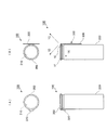
図7は、飲料缶100の他の構成例を示した図である。なお同図(A)は塞ぎ部材300が剥がされる前の飲料缶100の上面図および正面図であり、同図(B)は塞ぎ部材300が剥がされた後の飲料缶100の上面図および正面図である。なお同図(A)における飲料缶100の正面図では、飲料缶100の上部を断面で表示している。   FIG. 7 is a view showing another configuration example of the beverage can 100. 2A is a top view and a front view of the beverage can 100 before the closing member 300 is peeled off, and FIG. 2B is a top view and a front view of the beverage can 100 after the closing member 300 is peeled off. FIG. In addition, in the front view of the drink can 100 in the same figure (A), the upper part of the drink can 100 is displayed by the cross section.

同図(A)に示すように、本実施形態における飲料缶100には、上記と同様、上部に円形の開口210を有するとともに下部に底部を有し且つ筒状に形成され、清涼飲料などの飲料が内部に収容された容器本体(缶本体)200が設けられている。また、飲料缶100には、上記と同様、容器本体200の上部に位置する環状の縁部に接着され容器本体200の開口210の全体を塞ぐ塞ぎ部材300が設けられている。   As shown in FIG. 4A, the beverage can 100 according to the present embodiment has a circular opening 210 at the top and a bottom at the bottom and is formed in a cylindrical shape, as described above, and can be used for soft drinks and the like. A container body (can body) 200 in which a beverage is accommodated is provided. Further, the beverage can 100 is provided with a closing member 300 that is bonded to an annular edge located at the upper part of the container body 200 and closes the entire opening 210 of the container body 200, as described above.

図8は、容器本体200に塞ぎ部材300が取り付けられる直前の容器本体200および塞ぎ部材300を示した図である。
本実施形態における塞ぎ部材300には、上記と同様、円形に形成され容器本体200の上部に形成された開口210を覆うとともに、外周縁が容器本体200のカール部220に接着される覆い片の他の一例としての基部310が設けられている。また、基部310の縁部(外周縁)311から外側方向に突出するように設けられ塞ぎ部材300が容器本体200から剥がされる際にユーザにより把持(操作)される把持部320が設けられている。また本実施形態における塞ぎ部材300では、図7にも示すように、基部310の縁部311から外側方向に向かって突出するように設けられ容器本体200の外周面に対向配置されるとともにこの外周面に接着される接着片の他の一例としての接着部330が設けられている。なお、この接着部330は、基部310を挟み把持部320が設けられている側とは反対側に設けられている。
FIG. 8 is a view showing the container body 200 and the closing member 300 immediately before the closing member 300 is attached to the container body 200.
Similarly to the above, the closing member 300 in the present embodiment covers an opening 210 formed in a circular shape at the top of the container body 200, and a cover piece whose outer peripheral edge is bonded to the curled portion 220 of the container body 200. Another example base 310 is provided. Further, a grip portion 320 is provided so as to protrude outward from the edge (outer peripheral edge) 311 of the base portion 310 and gripped (operated) by the user when the closing member 300 is peeled off from the container main body 200. . Moreover, in the closing member 300 in this embodiment, as shown also in FIG. 7, it is provided so that it may protrude toward the outer side from the edge 311 of the base 310, and it is opposingly arranged to the outer peripheral surface of the container main body 200, and this outer periphery. An adhesive portion 330 is provided as another example of an adhesive piece that is adhered to the surface. The adhesive portion 330 is provided on the side opposite to the side on which the grip portion 320 is provided with the base portion 310 interposed therebetween.

本実施形態でも、基部310の縁部311の内側に位置する帯状の領域が容器本体200のカール部220に対して接着される。また、本実施形態では、上記帯状の領域のカール部220への接着により、把持部320および接着部330が下方に垂れ下がる。さらに、下方に垂れ下がった状態の接着部330と容器本体200の外周面とが接着される。これにより、図7(A)にて示した飲料缶100が完成する。なお、本実施形態における塞ぎ部材300も、上記にて説明した装着装置600によって容器本体200へ接着される。   Also in the present embodiment, a band-like region located inside the edge portion 311 of the base portion 310 is bonded to the curled portion 220 of the container main body 200. Further, in the present embodiment, the grip part 320 and the adhesive part 330 hang down due to the adhesion of the band-shaped region to the curled part 220. Furthermore, the adhesion part 330 and the outer peripheral surface of the container main body 200 in a state of hanging downward are adhered. Thereby, the beverage can 100 shown in FIG. 7A is completed. In addition, the closing member 300 in this embodiment is also adhere | attached on the container main body 200 with the mounting apparatus 600 demonstrated above.

ここで、飲料缶100の内部に収容された飲料が飲まれる際には、操作片の一例としての把持部320がユーザにより把持された後に、この把持部320が上方に引き上げられる。なお、本実施形態でも、容器本体200の外周面と把持部320との間に間隙が形成されており、付言すると、把持部320の先端側が容器本体200の外周面に接着されておらず、把持部320の把持が行いやすくなっている。そして把持部320が上方に引き上げられると、塞ぎ部材300のうちの容器本体200に接着された部位であって把持部320に近い側に位置する部位が、容器本体200から剥がれるようになる。   Here, when the beverage stored in the beverage can 100 is drunk, the grip portion 320 as an example of the operation piece is gripped by the user, and then the grip portion 320 is pulled upward. In the present embodiment, a gap is formed between the outer peripheral surface of the container main body 200 and the grip portion 320. In addition, the tip end side of the grip portion 320 is not bonded to the outer peripheral surface of the container main body 200. The gripping part 320 is easily gripped. When the grip portion 320 is pulled upward, a portion of the closing member 300 that is bonded to the container main body 200 and is located on the side close to the grip portion 320 is peeled off from the container main body 200.

その後、塞ぎ部材300の容器本体200からの剥がれが、把持部320が設けられている側から接着部330が設けられている側へ進行する。そして、塞ぎ部材300の容器本体200からの剥がれが終了すると、図7(B)に示すように、容器本体200の上部に形成された円形の開口210が露出するようになる。付言すると、本実施形態では、円形の開口210の全てが現れるようになる。   Thereafter, peeling of the closing member 300 from the container main body 200 proceeds from the side where the grip portion 320 is provided to the side where the adhesive portion 330 is provided. Then, when the peeling of the closing member 300 from the container body 200 is completed, the circular opening 210 formed in the upper part of the container body 200 is exposed as shown in FIG. 7B. In addition, in the present embodiment, all of the circular openings 210 appear.

なお本実施形態でも、塞ぎ部材300が容器本体200から剥がされた後、容器本体200の缶胴面に固着された、接着部330によって、塞ぎ部材300が容器本体200に取り付いたままの状態となる。このため、本実施形態でも、塞ぎ部材300がごみとなって散乱することが防止される。ここで、容器本体200の径が小さい場合、塞ぎ部材300と容器本体200との接着面積を確保しにくくなるが、本実施形態の構成のように、容器本体200の外周面に対して塞ぎ部材300を接着する場合、接着面積を確保しやすくなる。   In this embodiment as well, after the closing member 300 is peeled off from the container main body 200, the closing member 300 remains attached to the container main body 200 by the adhesive portion 330 fixed to the can body surface of the container main body 200. Become. For this reason, also in this embodiment, the blocking member 300 is prevented from being scattered as dust. Here, when the diameter of the container main body 200 is small, it is difficult to secure a bonding area between the closing member 300 and the container main body 200. However, as in the configuration of the present embodiment, the closing member is against the outer peripheral surface of the container main body 200. When bonding 300, it becomes easy to ensure a bonding area.

なお、ユーザにもよるが、内部の飲料がユーザにより飲まれる際に把持部320が下方へ引っ張られる。そしてこの場合は、図7(B)に示すように、基部310と接着部330との接続部あたりにて、塞ぎ部材300は折り曲げられる。これにより、容器本体200の開口210が塞ぎ部材300により再度覆われることが起きにくくなる。なお、本実施形態では、上記にて説明した第1スリット351と第2スリット352は設けられておらず、上記にて説明した実施形態に比べ、塞ぎ部材300を剥がす際に要する操作荷重は大きくなる。   Although depending on the user, when the beverage inside is drunk by the user, the grip portion 320 is pulled downward. In this case, as shown in FIG. 7B, the closing member 300 is bent around the connection portion between the base portion 310 and the bonding portion 330. This makes it difficult for the opening 210 of the container body 200 to be covered again by the closing member 300. In the present embodiment, the first slit 351 and the second slit 352 described above are not provided, and the operation load required to peel off the closing member 300 is larger than that in the embodiment described above. Become.

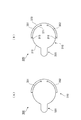
図9は、塞ぎ部材300の変形例を示した図である。なお、図9では容器本体200も併せて表示している。
同図(A)に示す塞ぎ部材300では、接着部330の幅Wを、図7、図8で示した接着部330の幅よりも大きくしている。付言すると、容器本体200の周方向に沿って容器本体200の外周面に接着される接着部330のこの周方向における幅Wを、図7、図8で示した接着部330の幅よりも大きくしている。ここで、このように接着部330の幅を大きくした場合、容器本体200と塞ぎ部材300との分離が更に起きにくくなる。
FIG. 9 is a view showing a modification of the closing member 300. In FIG. 9, the container main body 200 is also displayed.
In the closing member 300 shown in FIG. 7A, the width W of the bonding portion 330 is larger than the width of the bonding portion 330 shown in FIGS. In other words, the width W in the circumferential direction of the bonding portion 330 bonded to the outer peripheral surface of the container main body 200 along the circumferential direction of the container main body 200 is larger than the width of the bonding portion 330 shown in FIGS. doing. Here, when the width of the bonding portion 330 is increased as described above, the separation between the container body 200 and the closing member 300 is further less likely to occur.

なお同図(A)の態様では、基部310と接着部330とを接続する接続部340を設けるとともに、この接続部340の幅を、接着部330の幅よりも小さくしている。付言すると、本実施形態では、接着部330の根元の幅が接着部330の突出方向における先端の幅よりも小さくなっている。ここで、幅が小さいこの接続部340を設けない場合(幅の広い接着部330が直接、基部310に接続されている場合)、容器本体200から剥がした後の基部310を曲げにくくなる。付言すると、接着部330の延長線上に基部310が配置されやすくなり、飲料を飲む者の鼻がこの基部310に触れやすくなる。このため、本実施形態では、上記のように接続部340の幅を小さくすることで、塞ぎ部材300の剛性を部分的に弱め、基部310を倒れやすくしている。   In the aspect of FIG. 5A, a connection portion 340 that connects the base portion 310 and the adhesive portion 330 is provided, and the width of the connection portion 340 is made smaller than the width of the adhesive portion 330. In addition, in the present embodiment, the width of the base of the bonding portion 330 is smaller than the width of the tip in the protruding direction of the bonding portion 330. Here, when the connecting portion 340 having a small width is not provided (when the wide adhesive portion 330 is directly connected to the base portion 310), it is difficult to bend the base portion 310 after being peeled from the container body 200. In other words, the base 310 is easily disposed on the extension line of the bonding portion 330, and the nose of the person who drinks the beverage can easily touch the base 310. For this reason, in the present embodiment, by reducing the width of the connecting portion 340 as described above, the rigidity of the closing member 300 is partially weakened and the base portion 310 is easily tilted.

なお、接着部330を大きくする手法の他に、接着剤を変更し、塞ぎ部材300と容器本体200との付着強度を高めることによっても、容器本体200と塞ぎ部材300との分離が起きにくくなる。ところでこの場合、基部310と容器本体200との付着強度も大きくなり、基部310を容器本体200から剥がしにくくなってしまう。このため本実施形態では、接着部330と容器本体200との接着面積を大きくすることで、容器本体200と塞ぎ部材300との分離を起きにくくしている。   In addition to the method of enlarging the adhesion part 330, the adhesive body is changed and the adhesion strength between the closing member 300 and the container body 200 is increased to make it difficult for the container body 200 and the closing member 300 to be separated. . By the way, in this case, the adhesion strength between the base 310 and the container main body 200 also increases, and it becomes difficult to peel the base 310 from the container main body 200. For this reason, in this embodiment, separation of the container main body 200 and the closing member 300 is made difficult to occur by increasing the bonding area between the bonding portion 330 and the container main body 200.

図9(B)を参照し、塞ぎ部材300の他の変形例を説明する。
本図における塞ぎ部材300では、接着部330の形状と把持部320の形状とが同じとなるように接着部330および把持部320が形成されている。さらに説明すると、基部310を挟んだ一方側に接着部330が配置され、基部310を挟んだ他方側に把持部320が配置されている。さらに説明すると、把持部320は、円形に形成された基部310の中心を通る仮想直線9Bを挟んで相対する二つの領域のうちの一方の領域側に配置されるとともに、基部310の一端部であって仮想直線9Bと直交する方向における一端部に接続されている。また、接着部330は、上記二つの領域のうちの他方の領域側に配置されるとともに、基部310の他端部であって上記仮想直線9Bと直交する方向における他端部に接続されている。また本実施形態では、上記仮想直線9Bを対称軸として、塞ぎ部材300は線対称となるように形成されている。
With reference to FIG. 9B, another modification of the closing member 300 will be described.
In the closing member 300 in this figure, the adhesive portion 330 and the grip portion 320 are formed so that the shape of the adhesive portion 330 and the shape of the grip portion 320 are the same. More specifically, the adhesive portion 330 is disposed on one side of the base portion 310, and the grip portion 320 is disposed on the other side of the base portion 310. More specifically, the grip portion 320 is disposed on one region side of two regions facing each other across the virtual straight line 9B passing through the center of the base portion 310 formed in a circle, and at one end portion of the base portion 310. It is connected to one end in the direction orthogonal to the virtual straight line 9B. The adhesive portion 330 is disposed on the other region side of the two regions, and is connected to the other end portion of the base portion 310 in the direction orthogonal to the virtual line 9B. . In the present embodiment, the closing member 300 is formed so as to be line symmetric with respect to the virtual straight line 9B as an axis of symmetry.

図9(B)に示すこの塞ぎ部材300も、図6にて示した装着装置600によって、容器本体200に固定されるが、この際、塞ぎ部材300の位置(位相)が180°ずれていても、この塞ぎ部材300は容器本体200へ接着可能となる。このため本実施形態の構成では、管理項目の削減、および、作業ミスの軽減が期待できる。そしてこの場合、コストの削減が実現できる。   The closing member 300 shown in FIG. 9B is also fixed to the container main body 200 by the mounting device 600 shown in FIG. 6. At this time, the position (phase) of the closing member 300 is shifted by 180 °. However, the closing member 300 can be bonded to the container body 200. For this reason, in the configuration of the present embodiment, it is possible to reduce management items and reduce work errors. In this case, cost reduction can be realized.

9B…仮想直線、100…飲料缶、200…容器本体、210…開口、300…塞ぎ部材、310…基部、311…縁部、315…辺、320…把持部、330…接着部、371…第1の辺、372…第2の辺 9B ... Virtual straight line, 100 ... Beverage can, 200 ... Container body, 210 ... Opening, 300 ... Closing member, 310 ... Base, 311 ... Edge, 315 ... Side, 320 ... Gripping part, 330 ... Adhesive part, 371 ... First 1 side, 372 ... 2nd side

Claims (9)

筒状に形成され、軸方向における一端部に設けられた環状の縁部の内側に開口が形成され、内部に飲料が収容される缶本体と、
前記缶本体の前記一端部に接着され、当該缶本体に形成された前記開口を塞ぐ塞ぎ部材と、
を備え、
前記塞ぎ部材は、
前記缶本体の前記環状の縁部に接着され、当該缶本体に形成された前記開口を覆う覆い片と、
前記覆い片の外周縁から突出するように設けられ、当該覆い片が前記缶本体から剥がされる際にユーザにより操作される操作片と、
前記覆い片の前記外周縁から突出するように設けられるとともに前記缶本体の外周面に対向するように配置され、且つ、当該外周面に接着された接着片と、
を備える飲料缶。
A can body that is formed in a cylindrical shape, an opening is formed inside an annular edge provided at one end in the axial direction, and a beverage is accommodated therein;
A closing member that is bonded to the one end of the can body and closes the opening formed in the can body;
With
The closing member is
A cover piece that is bonded to the annular edge of the can body and covers the opening formed in the can body;
An operation piece that is provided so as to protrude from the outer peripheral edge of the cover piece and is operated by a user when the cover piece is peeled off from the can body,
An adhesive piece provided so as to protrude from the outer peripheral edge of the cover piece and arranged to face the outer peripheral surface of the can body, and bonded to the outer peripheral surface;
Beverage cans with
前記接着片は、前記覆い片を挟み前記操作片が設けられている側とは反対側に設けられていることを特徴とする請求項1記載の飲料缶。   The beverage can according to claim 1, wherein the adhesive piece is provided on a side opposite to the side on which the operation piece is provided with the cover piece interposed therebetween. 前記接着片の根元の幅が当該接着片の先端の幅よりも小さいことを特徴とする請求項1又は2に記載の飲料缶。   The beverage can according to claim 1 or 2, wherein a width of a base of the adhesive piece is smaller than a width of a tip of the adhesive piece. 前記覆い片は円形に形成され、
前記操作片は、円形に形成された前記覆い片の中心を通る仮想直線を挟んで相対する二つの領域のうちの一方の領域側に配置されるとともに、当該覆い片の一端部であって当該仮想直線と直交する方向における一端部に接続され、
前記接着片は、前記二つの領域のうちの他方の領域側に配置されるとともに、当該覆い片の他端部であって前記仮想直線と直交する方向における他端部に接続され、
前記塞ぎ部材は、前記仮想直線を対称軸として線対称となるように形成されていることを特徴とする請求項1乃至3の何れかに記載の飲料缶。
The covering piece is formed in a circular shape,
The operation piece is disposed on one of the two regions facing each other across an imaginary straight line passing through the center of the cover piece formed in a circle, and is one end portion of the cover piece. Connected to one end in the direction perpendicular to the virtual straight line,
The adhesive piece is disposed on the other region side of the two regions, and is connected to the other end portion in the direction perpendicular to the imaginary straight line at the other end portion of the covering piece,
The beverage can according to any one of claims 1 to 3, wherein the closing member is formed so as to be line symmetric with respect to the imaginary straight line as an axis of symmetry.
筒状に形成され、軸方向における一端部に設けられた環状の縁部の内側に開口が形成され、内部に飲料が収容される缶本体と、
前記缶本体の前記一端部に接着され、当該缶本体に形成された前記開口を塞ぐ塞ぎ部材と、
を備え、
前記塞ぎ部材は、
一端を有するとともに、当該一端から一方向に向かって延びるように設けられ当該一方向における下流側に他端を有し、前記缶本体に形成された前記開口の少なくとも一部を覆うように設けられ、当該他端が位置する側に向かって当該一端が移動するようにユーザにより操作されることで当該開口が露出するようになる覆い片と、
前記覆い片の前記他端に接続されるとともに、前記一方向とは反対方向に延びるように設けられ、前記缶本体の前記環状の縁部に接着された接着片と、
を備える飲料缶。
A can body that is formed in a cylindrical shape, an opening is formed inside an annular edge provided at one end in the axial direction, and a beverage is accommodated therein;
A closing member that is bonded to the one end of the can body and closes the opening formed in the can body;
With
The closing member is
The one end is provided so as to extend in one direction from the one end, the other end is provided on the downstream side in the one direction, and is provided so as to cover at least a part of the opening formed in the can body. A cover piece that exposes the opening by being operated by the user so that the one end moves toward the side where the other end is located;
An adhesive piece connected to the other end of the cover piece and extending in a direction opposite to the one direction, and bonded to the annular edge of the can body;
Beverage cans with
前記接着片は、前記環状の縁部の径方向における一端部から当該環状の縁部の径方向における他端部にかけて設けられていることを特徴とする請求項5記載の飲料缶。   The beverage can according to claim 5, wherein the adhesive piece is provided from one end portion in the radial direction of the annular edge portion to the other end portion in the radial direction of the annular edge portion. 前記接着片は、前記環状の縁部の径方向における一端部にて、前記覆い片の前記他端に接続されるとともに、当該環状の縁部の径方向における当該一端部から、当該環状の縁部の径方向における中央部にかけて配置されていることを特徴とする請求項5又は6に記載の飲料缶。   The adhesive piece is connected to the other end of the cover piece at one end in the radial direction of the annular edge, and from the one end in the radial direction of the annular edge to the annular edge It is arrange | positioned over the center part in the radial direction of a part, The drink can of Claim 5 or 6 characterized by the above-mentioned. 前記接着片は、前記覆い片の脇を通過するように設けられるとともに当該覆い片の縁部に接するように設けられ、当該覆い片の当該縁部に沿うように設けられるとともに当該縁部に接する第1の辺と、当該第1の辺よりも当該縁部から離れた側に位置し当該第1の辺に沿うように設けられた第2の辺と、当該接着片の先端部に位置するとともに当該覆い片の当該縁部とのなす角度が鋭角となるように配置され当該第1の辺と当該第2の辺とを接続する第3の辺と、を備えていることを特徴とする請求項5乃至7の何れかに記載の飲料缶。   The adhesive piece is provided so as to pass by the side of the cover piece, is provided so as to contact the edge of the cover piece, is provided along the edge of the cover piece, and is in contact with the edge. 1st edge | side, 2nd edge | side provided in the side far from the said edge part rather than the said 1st edge | side, and the said 1st edge | side are provided, and located in the front-end | tip part of the said adhesive piece And a third side that is arranged so that an angle formed with the edge of the cover piece is an acute angle and connects the first side and the second side. The beverage can according to any one of claims 5 to 7. 前記接着片は、前記缶本体の前記環状の縁部に接着されるとともに当該環状の縁部の内側に向かって延びるように配置され、
前記覆い片がユーザにより操作されることによって、前記缶本体に形成された前記開口の一部が露出した際、当該開口の他の部分が前記接着片により覆われていることを特徴とする請求項5乃至8の何れかに記載の飲料缶。
The adhesive piece is arranged to be bonded to the annular edge of the can body and to extend toward the inside of the annular edge,
When the cover piece is operated by a user and a part of the opening formed in the can body is exposed, the other part of the opening is covered with the adhesive piece. Item 9. A beverage can according to any one of Items 5 to 8.
JP2011151151A 2011-07-07 2011-07-07 Beverage cans Expired - Fee Related JP5901903B2 (en)

Priority Applications (1)

Application Number Priority Date Filing Date Title
JP2011151151A JP5901903B2 (en) 2011-07-07 2011-07-07 Beverage cans

Applications Claiming Priority (1)

Application Number Priority Date Filing Date Title
JP2011151151A JP5901903B2 (en) 2011-07-07 2011-07-07 Beverage cans

Publications (2)

Publication Number Publication Date
JP2013018497A true JP2013018497A (en) 2013-01-31
JP5901903B2 JP5901903B2 (en) 2016-04-13

Family

ID=47690350

Family Applications (1)

Application Number Title Priority Date Filing Date
JP2011151151A Expired - Fee Related JP5901903B2 (en) 2011-07-07 2011-07-07 Beverage cans

Country Status (1)

Country Link
JP (1) JP5901903B2 (en)

Citations (8)

* Cited by examiner, † Cited by third party
Publication number Priority date Publication date Assignee Title
JPH0196833U (en) * 1987-12-19 1989-06-27
JPH01177129U (en) * 1988-06-02 1989-12-18
JPH0491878U (en) * 1990-12-21 1992-08-11
JPH10120003A (en) * 1996-10-14 1998-05-12 Yukimasa Tazawa Seal for canned drink
JP2000264357A (en) * 1999-03-15 2000-09-26 Eiko:Kk Exterior cap used for beverage cans and the like and method of mounting the same
JP2002046759A (en) * 2000-08-02 2002-02-12 Dainippon Printing Co Ltd Beverage packaging
JP2003321024A (en) * 2002-04-30 2003-11-11 Toppan Printing Co Ltd Beverage container
JP2012236609A (en) * 2011-05-10 2012-12-06 Showa Aluminum Kan Kk Lid member, beverage container, and closing member

Patent Citations (8)

* Cited by examiner, † Cited by third party
Publication number Priority date Publication date Assignee Title
JPH0196833U (en) * 1987-12-19 1989-06-27
JPH01177129U (en) * 1988-06-02 1989-12-18
JPH0491878U (en) * 1990-12-21 1992-08-11
JPH10120003A (en) * 1996-10-14 1998-05-12 Yukimasa Tazawa Seal for canned drink
JP2000264357A (en) * 1999-03-15 2000-09-26 Eiko:Kk Exterior cap used for beverage cans and the like and method of mounting the same
JP2002046759A (en) * 2000-08-02 2002-02-12 Dainippon Printing Co Ltd Beverage packaging
JP2003321024A (en) * 2002-04-30 2003-11-11 Toppan Printing Co Ltd Beverage container
JP2012236609A (en) * 2011-05-10 2012-12-06 Showa Aluminum Kan Kk Lid member, beverage container, and closing member

Also Published As

Publication number Publication date
JP5901903B2 (en) 2016-04-13

Similar Documents

Publication Publication Date Title
JP5038730B2 (en) Easy-open container lid
EP3093257B1 (en) Container seal
JPWO2015145600A1 (en) Composite container
EP1607345A1 (en) Easily unsealable packaging body and method of manufacturing the same
CN105473463A (en) Container, and seal bar
KR101322238B1 (en) Packaging material, and packaged body formed by packaging solid product by packaging material
JP5421816B2 (en) Easy-open lid
JP5901903B2 (en) Beverage cans
JP2019023107A (en) Die cut opening for multilayered flexible package
JP5820173B2 (en) Beverage cans
JP5912286B2 (en) Lid member, beverage container
JP2020059548A (en) Absorbent article package
KR20180063153A (en) Easy-to-open container lid
JP2010230628A (en) Tubular container
JP5224865B2 (en) Labeled containers and packaging labels
JP5848045B2 (en) Beverage cans
JP2006240721A (en) Thermally insulated container
JP2012051585A (en) Packaging bag for wet sheets or the like
JP5105815B2 (en) Package
JP5647914B2 (en) Lid member, beverage container, and closing member
JP2012006657A (en) Beverage can
JP6367146B2 (en) Fastener and storage body and continuous sheet for storage body
JP2004359301A (en) Cap seal having no top face and method for manufacturing the same
JP5712080B2 (en) Beverage container
JPS638612Y2 (en)

Legal Events

Date Code Title Description
A621 Written request for application examination

Free format text: JAPANESE INTERMEDIATE CODE: A621

Effective date: 20140515

A977 Report on retrieval

Free format text: JAPANESE INTERMEDIATE CODE: A971007

Effective date: 20150113

A131 Notification of reasons for refusal

Free format text: JAPANESE INTERMEDIATE CODE: A131

Effective date: 20150217

A521 Written amendment

Free format text: JAPANESE INTERMEDIATE CODE: A523

Effective date: 20150327

A02 Decision of refusal

Free format text: JAPANESE INTERMEDIATE CODE: A02

Effective date: 20150929

A521 Written amendment

Free format text: JAPANESE INTERMEDIATE CODE: A523

Effective date: 20151224

A911 Transfer of reconsideration by examiner before appeal (zenchi)

Free format text: JAPANESE INTERMEDIATE CODE: A911

Effective date: 20160107

TRDD Decision of grant or rejection written
A01 Written decision to grant a patent or to grant a registration (utility model)

Free format text: JAPANESE INTERMEDIATE CODE: A01

Effective date: 20160301

A61 First payment of annual fees (during grant procedure)

Free format text: JAPANESE INTERMEDIATE CODE: A61

Effective date: 20160309

R150 Certificate of patent or registration of utility model

Ref document number: 5901903

Country of ref document: JP

Free format text: JAPANESE INTERMEDIATE CODE: R150

LAPS Cancellation because of no payment of annual fees