JP2013123728A - Seam welding equipment - Google Patents
Seam welding equipment Download PDFInfo
- Publication number
- JP2013123728A JP2013123728A JP2011273231A JP2011273231A JP2013123728A JP 2013123728 A JP2013123728 A JP 2013123728A JP 2011273231 A JP2011273231 A JP 2011273231A JP 2011273231 A JP2011273231 A JP 2011273231A JP 2013123728 A JP2013123728 A JP 2013123728A
- Authority
- JP
- Japan
- Prior art keywords
- electrode
- seam welding
- welding
- workpiece
- seam
- Prior art date
- Legal status (The legal status is an assumption and is not a legal conclusion. Google has not performed a legal analysis and makes no representation as to the accuracy of the status listed.)
- Granted
Links
Images

Landscapes
- Resistance Welding (AREA)
Abstract
【課題】自動車のフレームなど、急曲部を有するワークであっても、直線的部分と同様に、同一の溶接機でシーム溶接が可能な、シーム溶接用装置を提供すること。また、シーム溶接機自体をより小型化すること、複雑なワークでもスムースに溶接を行うことが出来るようにすること。
【解決手段】2つの回転電極でワークを挟み、2つの回転電極を回転させながら連続的に通電させ、抵抗溶接を行うシーム溶接装置であって、少なくとも一方の回転電極が円筒状電極であることからなる。
【選択図】図2
To provide a seam welding device capable of performing seam welding with the same welding machine even in the case of a workpiece having a sharp bend, such as a frame of an automobile, similarly to a straight portion. In addition, the seam welder itself must be made smaller, and even complex workpieces can be welded smoothly.
A seam welding apparatus that sandwiches a workpiece between two rotating electrodes and continuously energizes the two rotating electrodes to perform resistance welding, and at least one of the rotating electrodes is a cylindrical electrode. Consists of.
[Selection] Figure 2
Description
本発明は、シーム溶接用装置に関する。 The present invention relates to an apparatus for seam welding.
抵抗溶接としては、シーム溶接やスポット溶接などが知られているが、このうちスポット溶接は,2枚の板を重ね,棒状の電極(チップ)で加圧し,電圧を加えて電流を流し,溶接部をジュール発熱によって加熱してワークを局部的に溶融させて溶接材を冶金的に接合する溶接方法である。
一方、抵抗シーム溶接は,2つの円盤状の溶接電極を使用し,ワークを挟み込んだ状態で,連続的に回転させながら電流を断続的に通電することで連続した気密・水密性の高い溶接を行う溶接方法である。
Seam welding and spot welding are known as resistance welding. Of these, spot welding is a welding process in which two plates are stacked, pressed with a rod-shaped electrode (tip), a voltage is applied, and an electric current is applied. This is a welding method in which a part is heated by Joule heat to melt a workpiece locally to join a welding material metallurgically.
Resistance seam welding, on the other hand, uses two disc-shaped welding electrodes, and with continuous workpiece rotation, continuously energizing the current while continuously rotating the workpiece. It is a welding method to be performed.
つまり,スポット溶接も抵抗シーム溶接もともに抵抗溶接であるが,シームはスポットを連続的に重ねたものである。したがって、ワークの溶接強度は、スポット溶接に比べシーム溶接の方が高くなる。また、極薄材の耐密溶接が可能なため,製品材料費が安くて済む。また,高速溶接が可能なため加工費が安くなり,溶接技術に熟練度が不要なため人件費が安くなるなどの製造コスト面でのメリットが多い。そこで、特に自動車部品の溶接など、溶接品質の向上と製造コストの抑制が極めて高いレベルで望まれる分野においては、シーム溶接を適用することが望ましい。そして、近年ロボット搭載型のシーム溶接機や(例えば、特許文献1参照。)、2つの電極の回転軸の角度を調整できる記述が開示されており(例えば、特許文献2参照。)、従来に比べれば様々なワークに対応することが可能となってきている。 In other words, both spot welding and resistance seam welding are resistance welding, but the seam is a continuous stack of spots. Accordingly, the weld strength of the workpiece is higher in seam welding than in spot welding. In addition, it is possible to reduce the material cost of the product because it is possible to withstand tight welding of ultra-thin materials. In addition, there are many advantages in terms of manufacturing costs, such as high-speed welding, which reduces processing costs, and does not require skill in welding technology, which reduces labor costs. Therefore, it is desirable to apply seam welding in a field where improvement of welding quality and suppression of manufacturing cost are desired at a very high level, such as welding of automobile parts. In recent years, a robot-mounted seam welder (for example, see Patent Document 1) and a description that can adjust the angle of the rotation axis of two electrodes have been disclosed (for example, see Patent Document 2). In comparison, it has become possible to handle a variety of workpieces.
しかしながら、シーム溶接は、2枚の円盤状電極でワークを挟んで溶接を行うことから、溶接できるワークの形状に限界がある。例えば、自動車のフレーム(図1参照)の急曲部(曲率半径の短い曲線部分)である。自動車のフレーム(例えばドア部分のフレーム)は、重ねた板に突き合わせ部を作り、この突き合わせ部を挟み、好ましくはシーム溶接を行うものである(図2参照,その後ゴムなどを被せて、この突き合わせ部は見えないようにされる)。しかし、急曲部に至ると、本体部分に円盤状電極のどちらかがぶつかってしまう場合が多く、ワークに沿わせて電極を移動することが出来ず、当該急曲部分についてはシーム溶接を行うことができない。また、ぶつかる一方の円盤の径をなるべく小さくして対応することも考えられるが、この場合であっても給電部(円盤電極を回転稼働に支持しつつ給電を行うアーム部)には一定の径が必要であり、小さくできる円盤の径には限界があり、さらにもう一方の円盤の径を大きくしなければならないので、そちらが本体にぶつかることになり、問題の完全な解決には至らない。さらに、径を小さくすると、電極の摩耗も激しく、頻繁にメンテナンスが必要であるなど非効率となってしまう。 However, since seam welding is performed by sandwiching a workpiece between two disc-shaped electrodes, there is a limit to the shape of the workpiece that can be welded. For example, it is a sharply curved portion (curved portion with a short radius of curvature) of an automobile frame (see FIG. 1). An automobile frame (for example, a door part frame) is formed by forming a butt portion on a stacked plate, sandwiching the butt portion, and preferably performing seam welding (see FIG. 2, and then covering with rubber or the like). Part is made invisible). However, when reaching the sharply bent part, either of the disk-shaped electrodes often hits the main body part, and the electrode cannot be moved along the workpiece, and seam welding is performed on the sharply bent part. I can't. In addition, it is conceivable to reduce the diameter of one of the colliding disks as much as possible. However, even in this case, the feeding portion (the arm portion that feeds power while supporting the disc electrode in rotation operation) has a constant diameter. There is a limit to the diameter of the disk that can be made smaller, and the diameter of the other disk must be increased, so that it will hit the main body, and the problem will not be completely solved. Further, when the diameter is reduced, the electrode is severely worn, resulting in inefficiency such as frequent maintenance.
そのため、例えば自動車のフレームなど、急曲部を有するワークについては、直線的部分や曲がりが緩やかな部分についてはシーム溶接を行っているものの、急曲部についてはやむを得ずスポット溶接を行って対応しているのが現状である。 Therefore, for workpieces with sharp bends such as automobile frames, seam welding is performed for straight parts and parts with gentle bends, but spot welding is unavoidable for sharp bends. The current situation is.
そこで、本発明は、例えば自動車のフレームなど、急曲部を有するワークであっても、直線的部分と同様に、同一の溶接機でシーム溶接が可能な、シーム溶接用装置を提供することを目的とする。 Therefore, the present invention provides a seam welding apparatus capable of performing seam welding with the same welding machine, even in the case of a workpiece having a sharp bend, such as an automobile frame. Objective.
前記目的を達成するため、本発明のシーム溶接用装置は、2つの回転電極でワークを挟み、2つの回転電極を回転させながら連続的に通電させ、抵抗溶接を行うシーム溶接装置であって、少なくとも一方の回転電極が円筒状電極であることからなる。
また、上記のシーム溶接装置であって、一方の円筒状電極の回転軸と、他方の回転電極の回転軸から構成される角度が、90度±45度(ただし、90度を除く)となるように配置されていることが好適である。
また、前記他方の回転電極が、円盤状電極であることが好適である。
また、円盤状電極のワークに接する部分の厚さと、円筒状電極のワークに接する部分の厚さが同じであることが好適である。
また、円筒状電極内に、冷却管を有する冷却部が内蔵されていることが好適である。
また、三次元的な動きが可能なロボットに搭載されていることが好適である。
In order to achieve the above object, the seam welding apparatus of the present invention is a seam welding apparatus that sandwiches a workpiece between two rotating electrodes and continuously energizes the two rotating electrodes while performing resistance welding. At least one of the rotating electrodes is a cylindrical electrode.
Further, in the seam welding apparatus described above, an angle formed by the rotation axis of one cylindrical electrode and the rotation axis of the other rotation electrode is 90 ° ± 45 ° (however, excluding 90 °). It is preferable that they are arranged as described above.
Further, it is preferable that the other rotating electrode is a disk-shaped electrode.
In addition, it is preferable that the thickness of the portion of the disk-shaped electrode that contacts the workpiece and the thickness of the portion of the cylindrical electrode that contacts the workpiece are the same.
Further, it is preferable that a cooling part having a cooling pipe is built in the cylindrical electrode.
It is also preferable that the robot is mounted on a robot capable of three-dimensional movement.
本発明者は鋭意研究の結果、従来の2枚の円盤状電極という発想を捨て、少なくとも一方の回転電極を円筒状電極とすることで、直線的部分と急曲部を同一のシーム溶接機で溶接を可能としたものである。具体的には、円筒を被せるような形で、溶接部に対して円筒状電極の先端が沿うように回転していくので、急曲部についても、直線的部分と同様に電極を当てることが出来るものである。なお、本願において円筒状とは、中空部を有し、ワークに対して被さるような形で回転しながらシーム溶接が可能な形状を意味しており、必ずしも幾何学的に完璧な円筒であることを意味していない。 As a result of earnest research, the present inventor abandoned the idea of the conventional two disk-shaped electrodes, and at least one of the rotating electrodes was a cylindrical electrode, so that the straight portion and the sharply bent portion were the same seam welder. Welding is possible. Specifically, since the tip of the cylindrical electrode rotates along the welded part so as to cover the cylinder, the electrode can be applied to the sharply bent part as well as the linear part. It is possible. In the present application, the term “cylindrical” means a shape having a hollow portion and capable of seam welding while rotating so as to cover the workpiece, and is necessarily a geometrically perfect cylinder. Does not mean.
特に、一方を円盤状電極とし、両電極の回転軸を平行ではなく、90度±45度、好ましくは略90度に配置することで、本発明の利点を最大限に活用できる。ただし、ワークとのかみ合わせの観点から、厳密には90度から少しずらしてあることが好ましい。すなわち、仮に一方の円筒状電極の回転軸が鉛直線と略平行とした場合、もう一方の円盤状電極の回転軸が、水平面に略平行な方向に配置されており、円筒状電極の回転軸が、円盤状電極よりも内側(円盤状電極の給電部側)にあるように配置することで、これまでシーム溶接が不可能であるか非常に難しかった急曲部についても直線的部分と同様に電極を当てることが出来る。したがって、例えば自動車のフレームについては、素早く溶接が出来るため製造コストの軽減に資するだけでなく、溶接強度も上がり、自動車全体の強度を上げることも可能となるものである。さらには、シーム溶接機自体をより小型化することが可能である。円筒電極を下向きに、もう一方の電極を横向きに配置できるので、余分なスペースを必要としない(図3参照)。したがって、特に3次元的な動きを可能にする多軸の溶接ロボットに搭載した場合は、自動車のフレームのような複雑な形状のワークであっても、どこにも引っかかることがなく、スムースに溶接を行うことが可能である。 In particular, the advantage of the present invention can be utilized to the maximum by arranging one of the electrodes as a disk-like electrode and arranging the rotation axes of both electrodes at 90 ° ± 45 °, preferably approximately 90 °, not parallel. However, from the viewpoint of meshing with the workpiece, strictly speaking, it is preferable to be slightly shifted from 90 degrees. That is, if the rotation axis of one cylindrical electrode is substantially parallel to the vertical line, the rotation axis of the other disk-shaped electrode is arranged in a direction substantially parallel to the horizontal plane, and the rotation axis of the cylindrical electrode However, by arranging it so that it is on the inner side of the disc-shaped electrode (on the side of the feeding portion of the disc-shaped electrode), it is the same as the linear portion for the sharp bend that has been impossible or very difficult The electrode can be applied to. Therefore, for example, an automobile frame can be welded quickly, which not only contributes to the reduction in manufacturing cost, but also increases the welding strength, thereby increasing the overall strength of the automobile. Furthermore, the seam welder itself can be further downsized. Since the cylindrical electrode can be disposed downward and the other electrode can be disposed laterally, no extra space is required (see FIG. 3). Therefore, especially when it is mounted on a multi-axis welding robot that enables three-dimensional movement, even a workpiece with a complicated shape such as an automobile frame will not get caught anywhere, and welding can be performed smoothly. Is possible.
さらに、上記の構成からすれば、両電極の回転軸が平行でないにも関わらず、電極の摩耗に関して、円筒状電極はその円の径は変わらず、円筒が短くなるだけで済むので、効率が良くメンテナンスが容易である。なお、もう一方の電極は円盤状電極でも円筒状電極でも良いが、一方を円盤状電極とした場合には、円盤状電極の厚みと、円筒の壁の厚さがほぼ同じとすることで、溶接対象を挟む部分がより明確になり摩耗箇所も割合も予測しやすく、メンテナンスが容易である。 Furthermore, according to the above configuration, the cylindrical electrode has no change in the diameter of the circular electrode with respect to the wear of the electrode even though the rotation axes of both electrodes are not parallel. Good maintenance. The other electrode may be a disk-shaped electrode or a cylindrical electrode, but when one is a disk-shaped electrode, the thickness of the disk-shaped electrode is substantially the same as the thickness of the cylindrical wall, The part sandwiching the welding object becomes clearer, the wear part and the ratio are easy to predict, and maintenance is easy.
具体的かつ好適な構成の例としては、円筒状電極のハウジング(給電部)の上にサーボモータを設け、シリンダー・LMガイド等を介して上下の加圧及び移動を可能にし、3次元的な動きを可能にする多軸の溶接ロボットに搭載することが挙げられる。電極の材料・径や大きさは、通常のシーム溶接機の円盤状電極と同様に、対象とする部材に応じて適宜選択されるものであり、特に限定される必要はない。 As an example of a specific and preferable configuration, a servo motor is provided on a cylindrical electrode housing (power supply unit), and it is possible to press and move up and down via a cylinder / LM guide and the like in a three-dimensional manner. For example, it can be mounted on a multi-axis welding robot that enables movement. The material, diameter, and size of the electrode are appropriately selected according to the target member, as in the case of the disk-shaped electrode of a normal seam welder, and need not be particularly limited.
さらに、円筒状電極には、円筒の内部に注入口及び排出口を有する水冷管を有する部材を備えることが出来るため、冷却部をより先端の近くまで配置することが可能で、円盤電極に比べても冷却効率が高いという利点も有する。 Furthermore, since the cylindrical electrode can be provided with a member having a water-cooled tube having an inlet and an outlet inside the cylinder, it is possible to arrange the cooling part closer to the tip, compared to the disk electrode. However, it also has an advantage of high cooling efficiency.
本発明は、上記の構成を有するので、例えば自動車のフレームなど、急曲部を有するワークであっても、直線的部分と同様に、同一の溶接機でシーム溶接を行うことが出来る。また、シーム溶接機自体をより小型化すること、複雑なワークでもスムースに溶接を行うことが出来、さらには電極のメンテナンス及び冷却も容易である。 Since the present invention has the above-described configuration, seam welding can be performed with the same welding machine as in the case of the linear portion even for a workpiece having a sharply curved portion such as an automobile frame. In addition, the seam welder itself can be further miniaturized, even complex workpieces can be welded smoothly, and the maintenance and cooling of the electrodes are easy.
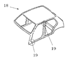
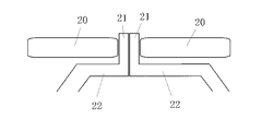
図1は自動車のフレームの一部を示す図であり、本発明はフレーム18の急曲部19を溶接するのに使用される。図2は自動車のフレーム18の溶接において、フレーム本体22、突き合わせ部21、円盤状電極20を示す断面の概念図である。
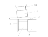
図3は、本発明のシーム溶接用装置1の一例を示す図である。
シーム溶接装置1には、円筒状電極2及び円盤状電極3が設けられており、円筒状電極2の先端と、円盤状電極3の側面がワークを挟めるように配置されている。
すなわち、円筒状電極2の回転軸(図示せず)と、円盤状電極3の回転軸(図示せず)の角度が、90度に近い形で配置されている。また、円筒状電極2の回転軸は、円盤状電極3の給電部4側にあるように配置されている。
即ち、突き合わせ部21を挟んだ際、円筒状電極2は、溶接部に対し上から被さるように配置されるため(図3、図4参照)、図1に示したような急曲部19を有するフレーム18に対しても、沿わせることが出来るため、直線的部分と同様に溶接が可能となるものである。なお、円筒状電極2の回転軸(図示せず)と、円盤状電極3の回転軸(図示せず)の角度は、ほぼ90度でなければならないものではなく、ワークの形状によって適宜設定されるものである。さらに、図4に示すように、完全に90度であるよりも、若干90度からずらして配置されることで、ワーク23に挟みやすくかみ合わせが良い場合もあるため、両回転軸間の角度は、90度±45度の角度が好適である。
FIG. 1 is a view showing a part of a frame of an automobile, and the present invention is used for welding a
FIG. 3 is a view showing an example of the
The
That is, the angle between the rotation axis (not shown) of the
That is, when the butted
円筒状電極2は、上部からほぼ直線上に配置されたサーボモータ5,スプラインジョイント6,シリンダー7,LMガイド8、給電部10、ハウジング13などを介して、円盤状電極3に向けて加圧しながら通電を行うことが出来、ワークを挟むことが出来る。一方、円盤状電極3は、給電部4を介して支持され、通電される。トランス11は給電部4,10に給電を可能としており、トルクコントロールモーター9はトルクのコントロールを可能にしている。支持部12は、各部品を支持すべく、適宜設けられる。。シーム溶接装置1は、ロボット14(全体は図示せず)に搭載されることで、三次元的な動きを可能にしている。
この構成によれば、図3から視覚的にも明らかなように、円筒状電極2と円盤状電極3が、給電部4,10や加圧機構も含めて、箱状に収まることになり、従来のシーム溶接機と比べると、余分なスペースや突出部が圧倒的に少ない。したがって、自動車のフレームの溶接のように、本体構造が複雑で、従来のシーム溶接機では、溶接中に溶接機が引っかかってしまい適用できないような箇所であっても、シーム溶接が可能となる。
The
According to this configuration, as is apparent from FIG. 3, the
また、円筒状電極2の摩耗は、円筒の長さが減っていく形で現れ、その円の径は維持されたままで済むので、上から加圧できる限り、メンテナンスや交換の必要がない。これは、二枚の円盤状電極を異なる回転軸の角度でワークに当てた場合に極めて重要な問題となるので、大きな利点となる。
Further, the wear of the
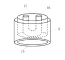
さらに、図5に示すように、円筒状電極2が中空部15を有していることから、中空部15内に、水冷管16を有する冷却部17を内蔵させることで、電極が冷却部に接する面積を一般的な円盤状電極よりもより多くとることが出来、さらにより先端近くまで冷却することを、より容易に構成できるという利点も有している。冷却管16及び冷却部17の材質は一般的にシーム溶接の電極の冷却に使用される材料を使用すれば良い。また、冷却管16の形状や、注入・排出口の数などは、図5に示したものに限定されるものではなく、複数の管を通したり、複数の注入口及び又は排出口を設けても良い。
Furthermore, as shown in FIG. 5, since the
1 シーム溶接用装置
2 円筒状電極
3 円盤状電極
4 給電部
5 サーボモータ
6 スプラインジョイント
7 シリンダー
8 LMガイド
9 トルクコントロールモーター
10 給電部
11 トランス
12 支持部
13 ハウジング
14 ロボット
15 中空部
16 水冷管
17 冷却部
18 自動車のフレーム
19 急曲部
20 円盤状電極
21 突き合わせ部
22 フレーム本体
23 ワーク
DESCRIPTION OF
Claims (8)
Priority Applications (1)
| Application Number | Priority Date | Filing Date | Title |
|---|---|---|---|
| JP2011273231A JP5922392B2 (en) | 2011-12-14 | 2011-12-14 | Seam welding equipment |
Applications Claiming Priority (1)
| Application Number | Priority Date | Filing Date | Title |
|---|---|---|---|
| JP2011273231A JP5922392B2 (en) | 2011-12-14 | 2011-12-14 | Seam welding equipment |
Publications (2)
| Publication Number | Publication Date |
|---|---|
| JP2013123728A true JP2013123728A (en) | 2013-06-24 |
| JP5922392B2 JP5922392B2 (en) | 2016-05-24 |
Family
ID=48775307
Family Applications (1)
| Application Number | Title | Priority Date | Filing Date |
|---|---|---|---|
| JP2011273231A Active JP5922392B2 (en) | 2011-12-14 | 2011-12-14 | Seam welding equipment |
Country Status (1)
| Country | Link |
|---|---|
| JP (1) | JP5922392B2 (en) |
Citations (8)
| Publication number | Priority date | Publication date | Assignee | Title |
|---|---|---|---|---|
| JPS61162278A (en) * | 1985-01-09 | 1986-07-22 | Nippon Yakin Kogyo Co Ltd | Self-traveling type seam welding machine containing roller electrode provided with cooling means |
| US4652718A (en) * | 1985-05-29 | 1987-03-24 | Honda Giken Kogyo Kabushiki Kaisha | Workpiece feeding apparatus in seam welding machine |
| JPS63138984U (en) * | 1987-02-27 | 1988-09-13 | ||
| JPH08118035A (en) * | 1994-10-28 | 1996-05-14 | Taiho Seiki Co Ltd | Seam welder |
| JPH08141751A (en) * | 1994-11-22 | 1996-06-04 | Futoshi Sumizaki | Rotary electrode roll and its fixed stator |
| JP2000005879A (en) * | 1998-06-24 | 2000-01-11 | Nippon Steel Corp | Resistance seam welding method and apparatus |
| JP2006082089A (en) * | 2004-09-14 | 2006-03-30 | Nachi Fujikoshi Corp | Robot seam welding method and apparatus |
| JP2007196287A (en) * | 2005-12-27 | 2007-08-09 | Aichi Sangyo Kk | Seam welding machine for welding inside r of work |
-
2011
- 2011-12-14 JP JP2011273231A patent/JP5922392B2/en active Active
Patent Citations (8)
| Publication number | Priority date | Publication date | Assignee | Title |
|---|---|---|---|---|
| JPS61162278A (en) * | 1985-01-09 | 1986-07-22 | Nippon Yakin Kogyo Co Ltd | Self-traveling type seam welding machine containing roller electrode provided with cooling means |
| US4652718A (en) * | 1985-05-29 | 1987-03-24 | Honda Giken Kogyo Kabushiki Kaisha | Workpiece feeding apparatus in seam welding machine |
| JPS63138984U (en) * | 1987-02-27 | 1988-09-13 | ||
| JPH08118035A (en) * | 1994-10-28 | 1996-05-14 | Taiho Seiki Co Ltd | Seam welder |
| JPH08141751A (en) * | 1994-11-22 | 1996-06-04 | Futoshi Sumizaki | Rotary electrode roll and its fixed stator |
| JP2000005879A (en) * | 1998-06-24 | 2000-01-11 | Nippon Steel Corp | Resistance seam welding method and apparatus |
| JP2006082089A (en) * | 2004-09-14 | 2006-03-30 | Nachi Fujikoshi Corp | Robot seam welding method and apparatus |
| JP2007196287A (en) * | 2005-12-27 | 2007-08-09 | Aichi Sangyo Kk | Seam welding machine for welding inside r of work |
Also Published As
| Publication number | Publication date |
|---|---|
| JP5922392B2 (en) | 2016-05-24 |
Similar Documents
| Publication | Publication Date | Title |
|---|---|---|
| JP5792712B2 (en) | Welding head and welding head assembly for an arc welding system | |
| JP5498463B2 (en) | Pressure control method for spot welding equipment | |
| KR20120029160A (en) | One side direction spot welding device | |
| US9868175B2 (en) | Seam welding method and seam welding device | |
| JP5783763B2 (en) | Spot welding method and spot welding apparatus | |
| CN117961301A (en) | Laser arc composite welding process for straight welded pipe production line | |
| JP5427746B2 (en) | Spot welding equipment | |
| US10150176B2 (en) | Barrel tank seam welder system | |
| JP7223651B2 (en) | Welding system and its operation method | |
| JP7278300B2 (en) | FRICTION STIR WELDING APPARATUS, OPERATION METHOD THEREOF, AND JOINT STRUCTURE | |
| US8851811B2 (en) | Stabilizer for dressing electrodes and method of using the same | |
| CN206561210U (en) | A kind of arc-ultrasonic ripple Rolling welding welder | |
| JP5922392B2 (en) | Seam welding equipment | |
| US20120273469A1 (en) | Planetary Resistance Welding Device And Methods Therefor | |
| KR20200141911A (en) | Welding apparatus | |
| CN204565394U (en) | The outer circumferential weld submerged arc welding system of the outer courage container of LNG low-temperature tanker | |
| KR102747977B1 (en) | Friction stir spot welding device and method for operating same | |
| JP5865132B2 (en) | Seam welding method and seam welding apparatus | |
| CN106425143B (en) | A composite welding device for arc ultrasonic roll welding | |
| JP4893906B2 (en) | Electrode tip shaping device and electrode tip shaping tool | |
| JP5780398B2 (en) | Spot welder | |
| JP2009090314A (en) | Welding gun | |
| JP2004330253A (en) | Method and apparatus for spot-welding | |
| JP5864363B2 (en) | Resistance welding apparatus and resistance welding method | |
| CN107350696B (en) | A positioning clamping device for welding |
Legal Events
| Date | Code | Title | Description |
|---|---|---|---|
| A621 | Written request for application examination |
Free format text: JAPANESE INTERMEDIATE CODE: A621 Effective date: 20140924 |
|
| A977 | Report on retrieval |
Free format text: JAPANESE INTERMEDIATE CODE: A971007 Effective date: 20151008 |
|
| A131 | Notification of reasons for refusal |
Free format text: JAPANESE INTERMEDIATE CODE: A131 Effective date: 20151020 |
|
| A521 | Request for written amendment filed |
Free format text: JAPANESE INTERMEDIATE CODE: A523 Effective date: 20151028 |
|
| A131 | Notification of reasons for refusal |
Free format text: JAPANESE INTERMEDIATE CODE: A131 Effective date: 20160308 |
|
| A521 | Request for written amendment filed |
Free format text: JAPANESE INTERMEDIATE CODE: A523 Effective date: 20160310 |
|
| TRDD | Decision of grant or rejection written | ||
| A01 | Written decision to grant a patent or to grant a registration (utility model) |
Free format text: JAPANESE INTERMEDIATE CODE: A01 Effective date: 20160405 |
|
| A61 | First payment of annual fees (during grant procedure) |
Free format text: JAPANESE INTERMEDIATE CODE: A61 Effective date: 20160414 |
|
| R150 | Certificate of patent or registration of utility model |
Ref document number: 5922392 Country of ref document: JP Free format text: JAPANESE INTERMEDIATE CODE: R150 |
|
| R250 | Receipt of annual fees |
Free format text: JAPANESE INTERMEDIATE CODE: R250 |
|
| R250 | Receipt of annual fees |
Free format text: JAPANESE INTERMEDIATE CODE: R250 |
|
| R250 | Receipt of annual fees |
Free format text: JAPANESE INTERMEDIATE CODE: R250 |
|
| R250 | Receipt of annual fees |
Free format text: JAPANESE INTERMEDIATE CODE: R250 |
|
| R250 | Receipt of annual fees |
Free format text: JAPANESE INTERMEDIATE CODE: R250 |
|
| R250 | Receipt of annual fees |
Free format text: JAPANESE INTERMEDIATE CODE: R250 |
|
| R250 | Receipt of annual fees |
Free format text: JAPANESE INTERMEDIATE CODE: R250 |