JP2013144403A - Method for manufacturing abutting portion - Google Patents
Method for manufacturing abutting portion Download PDFInfo
- Publication number
- JP2013144403A JP2013144403A JP2012005972A JP2012005972A JP2013144403A JP 2013144403 A JP2013144403 A JP 2013144403A JP 2012005972 A JP2012005972 A JP 2012005972A JP 2012005972 A JP2012005972 A JP 2012005972A JP 2013144403 A JP2013144403 A JP 2013144403A
- Authority
- JP
- Japan
- Prior art keywords
- core
- bag
- manufacturing
- shaped member
- granular material
- Prior art date
- Legal status (The legal status is an assumption and is not a legal conclusion. Google has not performed a legal analysis and makes no representation as to the accuracy of the status listed.)
- Granted
Links
Images



Classifications
-
- B—PERFORMING OPERATIONS; TRANSPORTING
- B29—WORKING OF PLASTICS; WORKING OF SUBSTANCES IN A PLASTIC STATE IN GENERAL
- B29B—PREPARATION OR PRETREATMENT OF THE MATERIAL TO BE SHAPED; MAKING GRANULES OR PREFORMS; RECOVERY OF PLASTICS OR OTHER CONSTITUENTS OF WASTE MATERIAL CONTAINING PLASTICS
- B29B11/00—Making preforms
- B29B11/02—Making preforms by dividing preformed material, e.g. sheets, rods
-
- B—PERFORMING OPERATIONS; TRANSPORTING
- B25—HAND TOOLS; PORTABLE POWER-DRIVEN TOOLS; MANIPULATORS
- B25J—MANIPULATORS; CHAMBERS PROVIDED WITH MANIPULATION DEVICES
- B25J15/00—Gripping heads and other end effectors
- B25J15/0023—Gripper surfaces directly activated by a fluid
-
- B—PERFORMING OPERATIONS; TRANSPORTING
- B29—WORKING OF PLASTICS; WORKING OF SUBSTANCES IN A PLASTIC STATE IN GENERAL
- B29C—SHAPING OR JOINING OF PLASTICS; SHAPING OF MATERIAL IN A PLASTIC STATE, NOT OTHERWISE PROVIDED FOR; AFTER-TREATMENT OF THE SHAPED PRODUCTS, e.g. REPAIRING
- B29C45/00—Injection moulding, i.e. forcing the required volume of moulding material through a nozzle into a closed mould; Apparatus therefor
- B29C45/17—Component parts, details or accessories; Auxiliary operations
- B29C45/40—Removing or ejecting moulded articles
- B29C45/44—Removing or ejecting moulded articles for undercut articles
- B29C45/4457—Removing or ejecting moulded articles for undercut articles using fusible, soluble or destructible cores
-
- B—PERFORMING OPERATIONS; TRANSPORTING
- B29—WORKING OF PLASTICS; WORKING OF SUBSTANCES IN A PLASTIC STATE IN GENERAL
- B29D—PRODUCING PARTICULAR ARTICLES FROM PLASTICS OR FROM SUBSTANCES IN A PLASTIC STATE
- B29D22/00—Producing hollow articles
- B29D22/003—Containers for packaging, storing or transporting, e.g. bottles, jars, cans, barrels, tanks
-
- B—PERFORMING OPERATIONS; TRANSPORTING
- B29—WORKING OF PLASTICS; WORKING OF SUBSTANCES IN A PLASTIC STATE IN GENERAL
- B29C—SHAPING OR JOINING OF PLASTICS; SHAPING OF MATERIAL IN A PLASTIC STATE, NOT OTHERWISE PROVIDED FOR; AFTER-TREATMENT OF THE SHAPED PRODUCTS, e.g. REPAIRING
- B29C41/00—Shaping by coating a mould, core or other substrate, i.e. by depositing material and stripping-off the shaped article; Apparatus therefor
- B29C41/02—Shaping by coating a mould, core or other substrate, i.e. by depositing material and stripping-off the shaped article; Apparatus therefor for making articles of definite length, i.e. discrete articles
- B29C41/14—Dipping a core
-
- B—PERFORMING OPERATIONS; TRANSPORTING
- B29—WORKING OF PLASTICS; WORKING OF SUBSTANCES IN A PLASTIC STATE IN GENERAL
- B29K—INDEXING SCHEME ASSOCIATED WITH SUBCLASSES B29B, B29C OR B29D, RELATING TO MOULDING MATERIALS OR TO MATERIALS FOR MOULDS, REINFORCEMENTS, FILLERS OR PREFORMED PARTS, e.g. INSERTS
- B29K2021/00—Use of unspecified rubbers as moulding material
-
- B—PERFORMING OPERATIONS; TRANSPORTING
- B29—WORKING OF PLASTICS; WORKING OF SUBSTANCES IN A PLASTIC STATE IN GENERAL
- B29K—INDEXING SCHEME ASSOCIATED WITH SUBCLASSES B29B, B29C OR B29D, RELATING TO MOULDING MATERIALS OR TO MATERIALS FOR MOULDS, REINFORCEMENTS, FILLERS OR PREFORMED PARTS, e.g. INSERTS
- B29K2995/00—Properties of moulding materials, reinforcements, fillers, preformed parts or moulds
- B29K2995/0037—Other properties
- B29K2995/0046—Elastic
-
- B—PERFORMING OPERATIONS; TRANSPORTING
- B29—WORKING OF PLASTICS; WORKING OF SUBSTANCES IN A PLASTIC STATE IN GENERAL
- B29K—INDEXING SCHEME ASSOCIATED WITH SUBCLASSES B29B, B29C OR B29D, RELATING TO MOULDING MATERIALS OR TO MATERIALS FOR MOULDS, REINFORCEMENTS, FILLERS OR PREFORMED PARTS, e.g. INSERTS
- B29K2995/00—Properties of moulding materials, reinforcements, fillers, preformed parts or moulds
- B29K2995/0037—Other properties
- B29K2995/0065—Permeability to gases
- B29K2995/0067—Permeability to gases non-permeable
Landscapes
- Engineering & Computer Science (AREA)
- Mechanical Engineering (AREA)
- Robotics (AREA)
- Manufacturing & Machinery (AREA)
- Moulds For Moulding Plastics Or The Like (AREA)
- Making Paper Articles (AREA)
- Molds, Cores, And Manufacturing Methods Thereof (AREA)
- Containers And Plastic Fillers For Packaging (AREA)
- Bag Frames (AREA)
Abstract
【課題】把持装置の手先部分を構成する当接部を容易に製造することができる当接部の製造方法を提供する。
【解決手段】弾性および気密性を有する素材(本実施形態ではゴム18)からなるゴム製の袋状部材6aと、該袋状部材6aの内部に充填される粒状物7と、を有する、把持装置1におけるワークと当接する部位を構成するための部材である当接部6の製造方法であって、粒状物7をバインダー11により固めて、袋状部材6aを成形するための芯材たる中子10を作成する工程と、中子10の周囲に弾性および気密性を有する素材たるゴム18製の被膜を形成して、袋状部材6aを形成する工程と、袋状部材6aの内部に存在する中子10を崩壊させる工程と、を有する。
【選択図】図10A contact portion manufacturing method capable of easily manufacturing a contact portion constituting a hand portion of a gripping device is provided.
A gripping member having a rubber bag-like member 6a made of a material having elasticity and airtightness (rubber 18 in this embodiment) and a granular material 7 filled in the bag-like member 6a. It is a manufacturing method of the contact part 6 which is a member for comprising the site | part which contacts the workpiece | work in the apparatus 1, Comprising: The granular material 7 is hardened with the binder 11, and it is a core material for shape | molding the bag-shaped member 6a A step of forming the child 10, a step of forming a film made of rubber 18 as a material having elasticity and airtightness around the core 10 to form the bag-like member 6 a, and the presence within the bag-like member 6 a The core 10 to be collapsed.
[Selection] Figure 10
Description
本発明は、把持装置の手先部分を構成する、ゴム製の袋状部材に粒状物を充填して構成される部材である当接部の製造方法の技術に関する。 The present invention relates to a technique of a manufacturing method of an abutting portion that is a member configured by filling a granular material into a rubber bag-like member that constitutes a hand portion of a gripping device.
従来、ワークを把持するための装置であって、種々の形状を有するワークを、手先部分等を交換することなく確実に把持することができる把持装置が開発されるに至っている。
そして、このような把持装置においては、ワークと直接当接する部位である当接部をワークの形状に対応させて変形させることにより、確実な把持状態を確保することが可能になっており、形状を柔軟に変形できる態様と、形状を堅固に保持する態様の、相反する二つの態様を一つの部材で実現できる当接部を有する構成としている。
2. Description of the Related Art Conventionally, a device for gripping a workpiece has been developed which can reliably grip a workpiece having various shapes without exchanging a hand portion or the like.
In such a gripping device, it is possible to ensure a reliable gripping state by deforming the contact portion, which is a portion that directly contacts the workpiece, in accordance with the shape of the workpiece. It is set as the structure which has a contact part which can implement | achieve two contradictory aspects of the aspect which can deform | transform flexibly, and the aspect which hold | maintains a shape firmly with one member.
このような把持装置に備えられる当接部は、ゴム製の袋状部材の内部に合成ムライト等の粒状物を充填したものが用いられている。
そして、例えば従来、ゴム製である袋状部材の製造方法に係る技術としては、例えば、以下に示す特許文献1に開示された技術が知られている。
As the contact portion provided in such a gripping device, a rubber bag-like member filled with a granular material such as synthetic mullite is used.
For example, as a technique related to a method for manufacturing a bag-shaped member made of rubber, for example, a technique disclosed in Patent Document 1 shown below is known.
把持装置の当接部に使用するゴム製の袋状部材は、内部を真空引きして使用するものであるため、真空度を確実に確保できるようにするためには、口金等を設けるための開口部を極力小さくすることが望ましい。
そのような小さい開口部を有する当接部用袋体を製造するためには、従来、特許文献1に示すようなプレス装置等を用いた加硫接着による方法で製造するのが一般的になっている。このような従来の製造方法では、熟練した作業者が手作業で袋状部材の仕上げ作業等を行う必要があり、袋状部材およびそれを用いて構成する当接部の製造コストが増大するとともに、大量生産が困難な状況となっていた。
また、特許文献1で開示された技術で製造したゴム製の袋状部材を当接部として使用するためには、内部に合成ムライト等の粒状物を充填する工程を別途設ける必要があった。
The rubber bag-like member used for the abutting portion of the gripping device is used by evacuating the inside, and in order to ensure the degree of vacuum reliably, a base or the like is provided. It is desirable to make the opening as small as possible.
In order to manufacture such a contact portion bag body having such a small opening, it has been generally manufactured by a method by vulcanization adhesion using a press device or the like as shown in Patent Document 1. ing. In such a conventional manufacturing method, it is necessary for a skilled worker to manually perform the finishing operation of the bag-shaped member, and the manufacturing cost of the bag-shaped member and the contact portion formed using the bag-shaped member increases. Mass production was difficult.
Moreover, in order to use the rubber bag-shaped member manufactured by the technique disclosed in Patent Document 1 as the contact portion, it is necessary to separately provide a step of filling the inside with a granular material such as synthetic mullite.
本発明は、斯かる現状の課題を鑑みてなされたものであり、把持装置の手先部分を構成する当接部を容易に製造することができる当接部の製造方法を提供することを目的としている。 The present invention has been made in view of such a current problem, and an object of the present invention is to provide a method of manufacturing an abutting portion that can easily manufacture the abutting portion that constitutes the hand portion of the gripping device. Yes.
本発明の解決しようとする課題は以上の如くであり、次にこの課題を解決するための手段を説明する。 The problem to be solved by the present invention is as described above. Next, means for solving the problem will be described.
即ち、請求項1においては、弾性および気密性を有する素材からなる袋状部材と、該袋状部材の内部に充填される粒状物と、を有する、把持装置におけるワークと当接する部位を構成するための部材である当接部の製造方法であって、前記粒状物をバインダーにより固めて、前記袋状部材を成形するための芯材たる中子を作成する工程と、前記中子の周囲に前記弾性および気密性を有する素材からなる被膜を形成して、前記袋状部材を形成する工程と、前記袋状部材の内部に存在する前記中子を崩壊させる工程と、を有するものである。 That is, in claim 1, the part which contacts the workpiece | work in a holding | grip apparatus which has the bag-shaped member which consists of a raw material which has elasticity and airtightness, and the granular material with which this bag-shaped member is filled is comprised. A method of manufacturing a contact portion which is a member for forming a core as a core material for molding the bag-shaped member by solidifying the granular material with a binder, and around the core The method includes a step of forming a film made of a material having elasticity and airtightness to form the bag-shaped member, and a step of collapsing the core existing in the bag-shaped member.
請求項2においては、前記中子を作成する工程は、前記粒状物と前記バインダーたる液化することなく昇華する所定の体積を有する固体を含む混合物を型の内部において圧縮し、所定の形状に成型することにより行うものである。 According to a second aspect of the present invention, in the step of creating the core, the mixture containing the granular material and a solid having a predetermined volume that sublimes without being liquefied as the binder is compressed in a mold and molded into a predetermined shape. This is what you do.
請求項3においては、前記中子を崩壊させる工程は、前記袋状部材を加熱して、あるいは、放置して、前記袋状部材の内部に存在する前記中子を構成する前記所定の体積を有する固体を昇華させることにより行うものである。 According to a third aspect of the present invention, in the step of collapsing the core, the predetermined volume constituting the core existing in the bag-shaped member is set by heating or leaving the bag-shaped member. It is performed by sublimating the solid that it has.
請求項4においては、前記中子を作成する工程は、前記粒状物と前記バインダーを含む混合物を型の内部において加熱し、所定の形状に成型することにより行うものである。 According to a fourth aspect of the present invention, the step of creating the core is performed by heating the mixture containing the granular material and the binder in a mold and molding the mixture into a predetermined shape.
請求項5においては、前記中子を崩壊させる工程は、前記袋状部材に外力を付与して、前記袋状部材の内部に存在する前記中子を粉砕することにより行うものである。 According to a fifth aspect of the present invention, the step of collapsing the core is performed by applying an external force to the bag-shaped member and pulverizing the core existing inside the bag-shaped member.
請求項6においては、前記中子を崩壊させる工程は、前記袋状部材の内部に水を注入して、前記袋状部材の内部に存在する前記中子を構成する前記バインダーを溶解させることにより行うものである。
In
請求項7においては、前記中子を作成する工程は、前記粒状物と前記バインダーたる液体を含む混合物を型の内部において冷却することにより前記液体を凝固させて、所定の形状に成型することにより行うものである。 According to a seventh aspect of the present invention, the step of creating the core includes solidifying the liquid by cooling the mixture containing the granular material and the liquid serving as the binder in a mold, and molding the liquid into a predetermined shape. Is what you do.
請求項8においては、前記中子を崩壊させる工程は、前記袋状部材を加熱して、あるいは、放置して、前記袋状部材の内部に存在する前記中子を構成する凝固させた前記液体を溶解させることにより行うものである。 In Claim 8, the process which collapses the said core heats the said bag-shaped member or leaves it, and the said solidified liquid which comprises the said core which exists in the inside of the said bag-shaped member Is carried out by dissolving
本発明の効果として、以下に示すような効果を奏する。 As effects of the present invention, the following effects can be obtained.
請求項1においては、袋状部材に粒状物を充填するための工程を別途設けることなく、容易に当接部を製造することができる。 According to the first aspect of the present invention, the contact portion can be easily manufactured without providing a separate step for filling the bag-like member with the granular material.
請求項2においては、袋状部材を形成するための芯材であって、粒状物を含む中子を容易に製造することができる。 In Claim 2, it is a core material for forming a bag-shaped member, Comprising: The core containing a granular material can be manufactured easily.
請求項3においては、袋状部材の内部で、容易に中子を崩壊させることができる。これにより、袋状部材の内部に粒状物を容易に充填することができる。 According to the third aspect, the core can be easily collapsed inside the bag-like member. Thereby, a granular material can be easily filled into the bag-shaped member.
請求項4においては、袋状部材を形成するための芯材であって、粒状物を含む中子を容易に製造することができる。
In
請求項5においては、袋状部材の内部で、容易に中子を崩壊させることができる。これにより、袋状部材の内部に粒状物を容易に充填することができる。 According to the fifth aspect, the core can be easily collapsed inside the bag-shaped member. Thereby, a granular material can be easily filled into the bag-shaped member.
請求項6においては、袋状部材の内部で、容易に中子を崩壊させることができる。これにより、袋状部材の内部に粒状物を容易に充填することができる。 In the sixth aspect, the core can be easily collapsed inside the bag-like member. Thereby, a granular material can be easily filled into the bag-shaped member.
請求項7においては、袋状部材を形成するための芯材であって、粒状物を含む中子を容易に製造することができる。
In
請求項8においては、袋状部材の内部で、容易に中子を崩壊させることができる。これにより、袋状部材の内部に粒状物を容易に充填することができる。 According to claim 8, the core can be easily collapsed inside the bag-like member. Thereby, a granular material can be easily filled into the bag-shaped member.
次に、発明の実施の形態を説明する。
まず始めに、本発明の一実施形態に係る製造方法により製造する当接部を有する把持装置の全体構成について、図1〜図3を用いて説明をする。
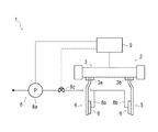
図1に示す如く、本発明の第一の実施形態に係る把持装置1は、ワーク等を把持して保持するための装置であり、把持部2、真空排気設備8、制御装置9等を備えている。
Next, embodiments of the invention will be described.
First, the overall configuration of a gripping device having a contact portion manufactured by a manufacturing method according to an embodiment of the present invention will be described with reference to FIGS.
As shown in FIG. 1, a gripping device 1 according to the first embodiment of the present invention is a device for gripping and holding a workpiece or the like, and includes a gripping portion 2, a vacuum exhaust equipment 8, a
把持部2は、把持装置1におけるワークを直接把持するための部位であり、駆動部3、複数の爪部4・5、複数の当接部6・6・・・等を備えている。
The gripping part 2 is a part for directly gripping a workpiece in the gripping device 1 and includes a
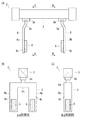
図1および図2(a)(b)(c)に示す如く、駆動部3は、二系統のスライダ部3a・3bを備えており、各スライダ部3a・3bを同一の軸方向に対して、それぞれ独立してまたは左右連動して往復変位させることができる装置である。駆動部3としては、例えば、ボールネジ・ナットおよびモータ等からなる往復動機構を備える電動アクチュエータ等を採用することができる。
As shown in FIGS. 1 and 2 (a), (b), and (c), the
各爪部4・5は、ワークを挟持するために備えられる一対の部位である。即ち、各爪部4・5は、該各爪部4・5の中間位置に配置されるワークを、各爪部4・5によって挟圧して保持するための部位である。
尚、各爪部4・5の形状は、把持対象となるワークの形状および大きさや、各スライダ部3a・3bのストローク量等を考慮して設定する。
Each nail | claw
The shapes of the
図2(a)(b)に示す如く、爪部4は、支持部4aと、該支持部4aから突設する二つの挟圧部4b・4bを備えている。挟圧部4b・4bは、互いに所定の間隔を隔てて配置されている。また、爪部4は、当接部6が付設される側の面を、付設面4cとしている。
爪部4は、支持部4aがスライダ部3aに対して固定されている。そして、制御装置9により、駆動部3を作動させてスライダ部3aをスライドさせて、各挟圧部4b・4bを、スライダ部3aのスライド方向に沿って往復動させる構成としている(図1参照)。
As shown in FIGS. 2A and 2B, the
As for
また、図2(a)(c)に示す如く、爪部5は、支持部5aと、該支持部5aから突設する一つの挟圧部5bを備えている。また、爪部5は、当接部6が付設される側の面を、付設面5cとしている。
爪部5は、支持部5aがスライダ部3bに対して固定されている。そして、制御装置9により、駆動部3を作動させてスライダ部3bをスライドさせて、挟圧部5bを、スライダ部3bのスライド方向に沿って往復動させる構成としている(図1参照)。
Further, as shown in FIGS. 2A and 2C, the
As for
次に、当接部6の構成について、説明をする。
前述した各爪部4・5は、所定の挟持力を達成するために、剛性を確保する必要があるため、鋼等所定の硬さを有する素材により構成するのが一般的である。
このため、ワークと各爪部4・5を直接当接させると、該各爪部4・5によってワークを破損等する可能性がある。
また、ワークは種々の形状に構成されるため、安定的な把持状態を実現するためには、各爪部4・5においてワークと当接する部位の形状をワークの形状に対応させる必要がある。
このため、把持部2においては、各挟圧部4b・4bおよび挟圧部5bのワークとの当接部位(各付設面4c・4c・5c)において、それぞれ各当接部6・6・6が付設される構成としている。
Next, the configuration of the
Each of the
For this reason, if the work and the
In addition, since the workpiece is configured in various shapes, in order to realize a stable gripping state, it is necessary to make the shape of the portion in contact with the workpiece in each of the
For this reason, in the holding part 2, in the contact part (each
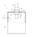
当接部6は、把持装置1においてワークと直接当接する部位であり、形状を柔軟に変形できる態様と、形状を堅固に保持する態様の、相反する二つの態様を一つの部材で実現できる部位であり、図3に示す如く、袋状部材6a、接続口6b等を備えている。
また、当接部6には、粒状物7を充填される構成としている。
尚、袋状部材6aは、切り傷等が生じることを抑制するために、外袋(図示せず)等によって、適宜被装される構成としてもよい。
The
Further, the
The bag-
袋状部材6aは、弾性および気密性を有するニトリルゴム(NBR)製の部材であり、NBR製のシートを適宜加硫溶着して、略直方体の袋状に形成された部材である。
また、袋状部材6aには孔部6fが形成されており、該孔部6fに、袋状部材6aの内外を連通するための部材である接続口6bが配設されている。
The bag-
Further, a
接続口6bは、封止部材6d・6dを介挿して、ナット6cを螺合して締結することによって、孔部6fの気密性を確保しつつ該孔部6fに付設されている。
また、接続口6bには、真空配管8bが接続されており、接続口6bの袋状部材6aに内包される端部において、フィルター6eが配設されている。
そして、フィルター6eによって、粒状物7が接続口6bから排出されることを防止する構成としている、
The
Further, a
And it is set as the structure which prevents that the
尚、本実施形態では、袋状部材6aの素材として、ニトリルゴム(NBR)を採用した場合を例示しているが、袋状部材6aを構成する素材をこれに限定するものではなく、弾性および気密性を有する素材であれば、作業環境等の条件に合わせて種々の素材を採用し得る。
また、本実施形態では、袋状部材6aの形状が、略直方体状である場合を例示しているが、本発明に係る把持装置を構成する当接部における袋状部材の形状をこれに限定するものではない。
In the present embodiment, the case where nitrile rubber (NBR) is employed as the material for the bag-
Further, in the present embodiment, the case where the shape of the bag-
粒状物7は、当接部6(より詳しくは、袋状部材6a)内に充填され、該袋状部材6a内を減圧し、粒状物7を構成する各粒子同士を互いに緊密に係留させることによって、袋状部材6aおよび粒状物7が一体化した状態において、任意の形状で硬化するものである。
The
当接部6には、1)硬化時における硬さが良好であること、2)より軽量であること、等の性質を有することが望まれるが、当接部6の硬化時における硬さや重量は、粒状物7の仕様を種々変更することによって変化する。
尚、本発明の一実施形態に係る当接部6の製造方法においては、粒状物7として、鋳砂等としても用いることができる合成ムライトを使用する構成としている。
そして、使用する合成ムライトの粒径や充填量等を適宜調整することによって、上記1および2)等の要求される機能を発揮するように、当接部6の性質を調整する構成としている。
The
In addition, in the manufacturing method of the
And the property of the
図1に示す如く、各当接部6・6・6(図2(a)(b)(c)参照)は、各爪部4・5の各挟圧部4b・4b・5bに付設された状態で、それぞれ真空配管8b・8b・8bによって真空排気設備8と接続されている。
As shown in FIG. 1, the
真空排気設備8は、把持装置1において当接部6を硬化および軟化させるための手段を構成するものであり、真空ポンプ8a、真空配管8b、電磁弁8c等を備えている。
尚、本実施形態では、真空排気設備8に真空ポンプ8aが備えられる場合を例示しているが、真空ポンプ8a以外の排気手段(例えば、エジェクター等)を備える構成とすることも可能である。
また、本発明に係る把持装置において、当接部の硬化および軟化を実現させるための手段は、必ずしも真空排気設備である必要はなく、当接部の硬化および軟化を実現することができる種々の態様のものを採用し得る。
The vacuum evacuation equipment 8 constitutes a means for hardening and softening the
In the present embodiment, the case where the
Further, in the gripping device according to the present invention, the means for realizing the hardening and softening of the abutting portion is not necessarily a vacuum evacuation facility, and various means capable of realizing the hardening and softening of the abutting portion. The thing of an aspect may be employ | adopted.
当接部6は、真空ポンプ8aを作動させて袋状部材6aの内部を減圧すると、袋状部材6aの内容積に対する粒状物7の体積比率が増大し、該袋状部材6a内に充填されている粒状物7を構成する各粒子がより緊密に係留することによって硬化するため、このとき、その形状を堅固に保持する態様を呈する。
When the abutting
このような当接部6を、各爪部4・5による挟持圧によって、柔軟な状態でワークに押圧すると、該当接部6をワーク表面の凹凸部に入り込ませることができるため、当接部6をワークの外面形状に倣わせることができる。
When such a
また、当接部6をワークの外面形状に倣わせた状態で真空排気設備8を作動させることによって、当接部6をワークの外面形状に対応した(倣わせた)形状で硬化させることができるため、ワークの外面形状に対応した堅固な態様の当接部6を形成できる。
Further, by operating the evacuation equipment 8 in a state where the
次に、本発明の一実施形態に係る当接部6の製造方法について、図4〜図12を用いて説明をする。
本発明の一実施形態に係る当接部6の製造方法では、図4に示すような中子10を用いて、袋状部材6aを製造する構成としている。
図4(a)に示す如く、中子10は複数の粒子の集合体である粒状物7を、バインダー11で結合して、略直方体の形状を有する固体として形成したものである。
尚、本発明の一実施形態に係る当接部6の製造方法に使用する中子10の形状は、略直方体に限定されず、所望する袋状部材6aの形状に対応させて、例えば、コーナー部をR形状としたり、面取り部を設けたりするような形状であってもよい。
Next, the manufacturing method of the
In the manufacturing method of the
As shown in FIG. 4 (a), the
In addition, the shape of the core 10 used in the method for manufacturing the
このように、中子10は、粒状物7をバインダー11で固めることによって、略直方体状の形状に形成されているが、中子10の形状・大きさを決定するに際しては、当接部6としての機能を考慮して、袋状部材6aに必要な内容積を確保するとともに、当該内容積に対して充填する必要がある粒状物7の量を確保する構成としている。
As described above, the
ここで、中子10の作成方法について、さらに詳細に説明をする。
ここではまず、第一の実施形態に係る中子10である第一の中子10Aの作成方法について説明をする。
図5(a)に示す如く、第一の中子10Aは、当接部6において袋状部材6aの中に充填されるべき部材である粒状物7を、第一のバインダー11たるレジン11Aで固めることによって、作成している。
レジン11Aは、鋳造において用いる中子を製作する際に、鋳砂を固めるために一般的に用いられるフェノール樹脂等からなる素材である。
そして、粒状物7とレジン11Aを混ぜ合わせたものを型16に入れておき、その状態で加熱することによりレジン11Aを軟化させて、粒状物7の各粒子を結合させることにより、所望する形状を有する第一の中子10Aを作成する構成としている。
Here, the method for creating the core 10 will be described in more detail.
Here, first, a method of creating the
As shown in FIG. 5A, the
The
Then, a mixture of the
中子10の外形寸法は、例えば、図4(b)に示すように、内部に空隙部10aを形成することによって調整することができる。そして、中子10の外形寸法を調整することによって、袋状部材6aの内容積を調整することができる。
そして、このようにして袋状部材6aの内容積を調整することによって、袋状部材6aの内容積に対する中子10に含まれる粒状物7の量の比率を調整することができる。
例えば、このような空隙部10aを形成する方法としては、ドライアイス等で作成した所定の体積を有する塊を包み込んだ状態で、中子10を作成することによって実現することができる。
The outer dimension of the core 10 can be adjusted, for example, by forming a
And the ratio of the quantity of the
For example, a method for forming such a
次に、第二の実施形態に係る中子10である第二の中子10Bの作成方法について説明をする。
図5(b)に示す如く、第二の中子10Bは、当接部6において袋状部材6aの中に充填されるべき部材である粒状物7を、第二のバインダー11たる水ガラス11Bで固めることによって、作成している。
水ガラス11Bは、鋳造において用いる中子を製作する際に、鋳砂を固めるために一般的に用いられる珪酸ナトリウム等からなる素材である。
そして、粒状物7と水ガラス11Bを混ぜ合わせたものを型16に入れておき、その状態で加熱することにより水ガラス11Bを軟化させて、粒状物7の各粒子を結合させることにより、所望する形状を有する第二の中子10Bを作成する構成としている。
Next, a method for creating the
As shown in FIG. 5B, the
The
Then, a mixture of the
次に、第三の実施形態に係る中子10である第三の中子10Cの作成方法について説明をする。
図6(a)に示す如く、第三の中子10Cは、当接部6において袋状部材6aの中に充填されるべき部材である粒状物7を、第三のバインダー11たる無機塩11Cで固めることによって、作成している。
無機塩11Cは、鋳造において用いる中子を製作する際に、鋳砂を固めるために一般的に用いられる主として珪酸ソーダからなる素材である。
そして、粒状物7と無機塩11Cを混ぜ合わせたものを型16に入れておき、その状態で加熱することにより無機塩11Cを軟化させて、粒状物7の各粒子を結合させることにより、所望する形状を有する第三の中子10Cを作成する構成としている。
Next, a method of creating the
As shown in FIG. 6A, the
The
Then, a mixture of the
次に、第四の実施形態に係る中子10である第四の中子10Dの作成方法について説明をする。
図6(b)に示す如く、第四の中子10Dは、当接部6において袋状部材6aの中に充填されるべき部材である粒状物7を、第四のバインダー11たる液体である水11Dで固めることによって、作成している。
この場合、粒状物7と水11Dを混ぜ合わせたものを型16に入れておき、その状態で冷却して水11Dを凝固させる(氷にする)ことにより、所望する形状を有する第四の中子10Dを作成する構成としている。
尚、本実施形態では、液体たる第四のバインダー11として水11Dを採用する場合を例示しているが、当該液体は、所定の温度域で凝固および溶解が可能な性質を有するものであればよく、第四のバインダー11として採用する液体を水11Dに限定するものではない。
Next, a method for creating a
As shown in FIG. 6B, the
In this case, a mixture of the
In the present embodiment, the case where the
次に、第五の実施形態に係る中子10である第五の中子10Eの作成方法について説明をする。
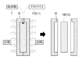
図7に示す如く、第五の中子10Eは、当接部6において袋状部材6aの中に充填されるべき部材である粒状物7を、第五のバインダー11たる液化することなく昇華する所定の体積を有する固体であるドライアイス11Eで固めることによって、作成している。
そして、粒状物7と粉末状のドライアイス11E等を混ぜ合わせたものを型16に入れておき、その状態で圧縮して、粒状物7をドライアイス11Eで固めることにより、所望する形状を有する第五の中子10Eを作成する構成としている。
尚、本実施形態では、液化することなく昇華する所定の体積を有する固体たる第五のバインダー11としてドライアイス11Eを採用する場合を例示しているが、当該固体は、所定の温度域で昇華することが可能なものであればよく、第五のバインダー11として採用する固体をドライアイス11Eに限定するものではない。
Next, a method for creating the
As shown in FIG. 7, the
And what mixed
In this embodiment, the case where the
また、本実施形態では、第一〜第五の実施形態に係る各中子10A〜10Eを例示して説明をしているが、本発明の一実施形態に係る当接部6の製造方法において使用する中子10の材質をこれらに限定するものはなく、粒状物7を結合させて固形状に固めることが可能であり、かつ、崩壊性がよい(容易に崩すことができる)材質であれば、その他種々の材質を採用することが可能である。
Moreover, in this embodiment, although each core 10A-10E which concerns on 1st-5th embodiment is illustrated and demonstrated, in the manufacturing method of the
次に、中子10を用いた当接部6の製造方法について、説明をする。
まずここでは、本発明の第一の実施形態に係る当接部6の製造方法について、説明をする。
本発明の第一の実施形態に係る当接部6の製造方法では、これまでに説明した各実施形態に係る各中子10A〜10Eを用いて、いわゆる射出成形の手法によって、袋状部材6aを製造するようにしている。
Next, the manufacturing method of the
First, the manufacturing method of the
In the manufacturing method of the
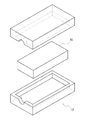
まず、図8および図9に示すような金型17内に中子10を配置する。
このとき、図9に示すように、金型17における中子10の周囲には、所定の隙間を確保するように、中子10と金型17の間には適宜スペーサ等を介装しておく。
そして、金型17内に液状原料たるゴム18を射出すると、中子10の回りに弾性および気密性を有するゴム18の被膜が形成され、この被膜が袋状部材6aとなる。
First, the
At this time, as shown in FIG. 9, an appropriate spacer or the like is interposed between the core 10 and the
Then, when
そして、本発明の第一の実施形態に係る当接部6の製造方法では、続いて、中子10を崩壊させる工程に移行する。
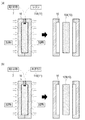
例えば、図10(a)に示す如く、中子10が第一の中子10Aや第二の中子10Bである場合には、中子10を包み込んでいる状態の袋状部材6aに対して、外部から打撃を加えることによって、中子10を崩壊させることができる。
そして、中子10を崩壊させることによって、中子10を構成していた粒状物7を、各粒子が再び独立して流動することができる状態に復元することができる。
And in the manufacturing method of the
For example, as shown in FIG. 10A, when the
And by collapsing the
このような構成により、袋状部材6aの内部に粒状物7を充填する作業に替えて、袋状部材6aに打撃を加えるだけで、容易に袋状部材6a内に粒状物7を充填した状態とすることができる。
そして後は、開口部を形成したり、接続口6b等の必要な部材を組み付けたりするだけで、容易に当接部6を製造することが可能になる。
With such a configuration, the bag-
After that, the
また、例えば、図10(b)に示す如く、中子10が第三の中子10Cである場合には、中子10を包み込んでいる状態の袋状部材6aに対して、内部に水を注入することによって、中子10を崩壊させることができる。
そして、中子10を崩壊させるとともに、袋状部材6a内を乾燥させることによって、中子10を構成していた粒状物7を、各粒子が再び独立して流動することができる状態に復元することができる。
For example, as shown in FIG. 10B, when the
Then, by disintegrating the
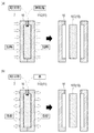
即ち、本発明の一実施形態に係る当接部6の製造方法において、中子10を作成する工程は、粒状物7とバインダー11(第一〜第三の各バインダー11A・11B・11C)を含む混合物を型16の内部において加熱し、所定の形状に成型することにより行うものである。
このような構成により、袋状部材6aを形成するための芯材であって、粒状物7を含む中子10(第一〜第三の各中子10A・10B・10C)を容易に製造することができる。
That is, in the manufacturing method of the
With this configuration, the core 10 (first to
また、本発明の一実施形態に係る当接部6の製造方法において、中子10(第一および第二の各中子10A・10B)を崩壊させる工程は、袋状部材6aに外力を付与して、袋状部材6aの内部に存在する各中子10A・10Bを粉砕することにより行うものである。
このような構成により、袋状部材6aの内部で、容易に中子10(第一および第二の各中子10A・10B)を崩壊させることができる。これにより、袋状部材6aの内部に粒状物7を容易に充填することができる。
Moreover, in the manufacturing method of the
With such a configuration, the core 10 (first and
また、本発明の一実施形態に係る当接部6の製造方法において、中子10(第三の中子10C)を崩壊させる工程は、袋状部材6aの内部に水を注入して、袋状部材6aの内部に存在する第三の中子10Cを構成する第三のバインダー11たる無機塩11Cを溶解させることにより行うものである。
このような構成により、袋状部材6aの内部で、容易に中子10(第三の中子10C)を崩壊させることができる。これにより、袋状部材6aの内部に粒状物7を容易に充填することができる。
Moreover, in the manufacturing method of the
With such a configuration, the core 10 (
あるいは、例えば、図11(a)に示す如く、中子10が第四の中子10Dである場合には、中子10を包み込んでいる状態の袋状部材6aを、加熱したり、あるいは、例えば常温で放置することによって、中子10を崩壊させることができる。
そして、中子10を崩壊させるとともに、袋状部材6a内を乾燥させることによって、中子10を構成していた粒状物7を、各粒子が再び独立して流動することができる状態に復元することができる。
Alternatively, for example, as shown in FIG. 11A, when the
Then, by disintegrating the
即ち、本発明の一実施形態に係る当接部6の製造方法において、中子10(第四の中子10D)を作成する工程は、粒状物7と第四のバインダー11たる液体(本実施形態では水11D)を含む混合物を型16の内部において冷却することにより水11Dを凝固させて、所定の形状に成型することにより行うものである。
このような構成により、袋状部材6aを形成するための芯材であって、粒状物7を含む中子10(第四の中子10D)を容易に製造することができる。
That is, in the manufacturing method of the
With such a configuration, a core 10 (
また、本発明の一実施形態に係る当接部6の製造方法において、中子10(第四の中子10D)を崩壊させる工程は、袋状部材6aを加熱して、あるいは、放置して、袋状部材6aの内部に存在する第四の中子10Dを構成する第四のバインダー11たる凝固させた液体(本実施形態では、凝固させた水11D(即ち、氷))を溶解させることにより行うものである。
このような構成により、袋状部材6aの内部で、容易に中子10(第四の中子10D)を崩壊させることができる。これにより、袋状部材6aの内部に粒状物7を容易に充填することができる。
Moreover, in the manufacturing method of the
With such a configuration, the core 10 (
さらに、例えば、図11(b)に示す如く、中子10が第五の中子10Eである場合には、中子10を包み込んでいる状態の袋状部材6aを、加熱したり、あるいは、常温で放置することによって、中子10を崩壊させることができる。
そして、中子10を崩壊させることによって、中子10を構成していた粒状物7を、各粒子が再び独立して流動することができる状態に復元することができる。
Further, for example, as shown in FIG. 11B, when the
And by collapsing the
即ち、本発明の一実施形態に係る当接部6の製造方法において、中子10を作成する工程は、粒状物7とバインダー11たる液化することなく昇華する所定の体積を有する固体(本実施形態では、ドライアイス11E)を含む混合物を型16の内部において圧縮し、所定の形状に成型することにより行うものである。
このような構成により、袋状部材6aを形成するための芯材であって、粒状物7を含む中子10(第五の中子10E)を容易に製造することができる。
That is, in the manufacturing method of the
With such a configuration, a core 10 (
また、本発明の一実施形態に係る当接部6の製造方法において、中子10を崩壊させる工程は、袋状部材6aを加熱して、あるいは、放置して、袋状部材6aの内部に存在する中子10を構成するバインダー11たる所定の体積を有する固体(本実施形態では、ドライアイス11E)を昇華させることにより行うものである。
このような構成により、袋状部材6aの内部で、容易に中子10(第五の中子10E)を崩壊させることができる。これにより、袋状部材6aの内部に粒状物7を容易に充填することができる。
Moreover, in the manufacturing method of the
With such a configuration, the core 10 (
次に、本発明の第二の実施形態に係る当接部6の製造方法について、説明をする。
本発明の第二の実施形態に係る当接部6の製造方法では、これまでに説明した各実施形態に係る各中子10A〜10Eを用いて、いわゆるディップ(浸潰)成形の手法によって、袋状部材6aを製造するようにしている。
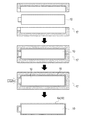
図12に示す如く、液状原料たるゴム18に、芯材となる中子10を浸潰させると、中子10の回りに弾性および気密性を有するゴム18の被膜を形成することができ、この被膜が袋状部材6aとなる。
Next, the manufacturing method of the
In the manufacturing method of the
As shown in FIG. 12, when the core 10 serving as the core material is crushed in the
そして、本発明の第二の実施形態に係る当接部6の製造方法においても、本発明の第一の実施形態に係る当接部6の製造方法と同様に、以後、中子10を崩壊させる工程に移行する。中子10を崩壊させる工程は、本発明の第一の実施形態に係る当接部6の製造方法における当該工程と共通の工程を採用することができる。
And also in the manufacturing method of the
このように、本発明の第一および第二の各実施形態に係る当接部6の製造方法においては、まず、上述したような方法により、粒状物7を含む構成である中子10を作成し、その作成した中子10を芯材として、袋状部材6aを製造する構成としている。
そしてさらに、本発明の第一および第二の各実施形態に係る当接部6の製造方法においては、中子10を芯材とする袋状部材6aにおいて、その袋状部材6aの内部で中子10を崩壊させることによって、容易に袋状部材6aの中に粒状物7を充填する構成としている。
Thus, in the manufacturing method of the
Furthermore, in the method for manufacturing the
即ち、本発明の一実施形態に係る当接部の製造方法は、弾性および気密性を有する素材(本実施形態ではゴム18)からなるゴム製の袋状部材6aと、該袋状部材6aの内部に充填される粒状物7と、を有する、把持装置1におけるワークと当接する部位を構成するための部材である当接部6の製造方法であって、粒状物7をバインダー11により固めて、袋状部材6aを成形するための芯材たる中子10を作成する工程と、中子10の周囲に弾性および気密性を有する素材たるゴム18製の被膜を形成して、袋状部材6aを形成する工程と、袋状部材6aの内部に存在する中子10を崩壊させる工程と、を有するものである。
このような構成により、袋状部材6aに粒状物7を充填するための工程を別途設けることなく、容易に当接部6を製造することができる。
That is, the manufacturing method of the contact part according to one embodiment of the present invention includes a rubber bag-
With such a configuration, the
尚、本実施形態では、において、射出成形による第一の実施形態とディップ成形による第二の実施形態を例示して説明をしているが、袋状部材6aの製造方法により、本発明の一実施形態に係る当接部6の製造方法を限定するものではなく、中子10の回りに弾性および気密性を有する素材(例えば、ゴム18や合成樹脂等)からなる被膜を形成し得る方法であれば、種々の袋状部材6aの製造方法を採用することができる。
In the present embodiment, the first embodiment by injection molding and the second embodiment by dip molding are illustrated and described. However, according to the manufacturing method of the bag-shaped
1 把持装置
2 把持部
6 当接部
6a 袋状部材
10 中子
11 バインダー
12 金型
DESCRIPTION OF SYMBOLS 1 Gripping device 2
Claims (8)
該袋状部材の内部に充填される粒状物と、
を有する、把持装置におけるワークと当接する部位を構成するための部材である当接部の製造方法であって、
前記粒状物をバインダーにより固めて、前記袋状部材を成形するための芯材たる中子を作成する工程と、
前記中子の周囲に前記弾性および気密性を有する素材からなる被膜を形成して、前記袋状部材を形成する工程と、
前記袋状部材の内部に存在する前記中子を崩壊させる工程と、
を有する、
ことを特徴とする当接部の製造方法。 A bag-like member made of a material having elasticity and airtightness;
A granular material filled in the bag-shaped member;
A manufacturing method of a contact portion that is a member for configuring a portion that contacts a workpiece in a gripping device,
A step of solidifying the granular material with a binder and creating a core as a core for forming the bag-shaped member;
Forming a film made of a material having elasticity and airtightness around the core, and forming the bag-shaped member;
A step of collapsing the core existing in the bag-shaped member;
Having
A method for manufacturing the contact portion.
前記粒状物と前記バインダーたる液化することなく昇華する所定の体積を有する固体を含む混合物を型の内部において圧縮し、所定の形状に成型することにより行う、
ことを特徴とする請求項1に記載の当接部の製造方法。 The step of creating the core includes
A mixture containing a solid having a predetermined volume that sublimes without being liquefied as the binder and the binder is compressed in a mold and molded into a predetermined shape.
The manufacturing method of the contact part of Claim 1 characterized by the above-mentioned.
前記袋状部材を加熱して、あるいは、放置して、
前記袋状部材の内部に存在する前記中子を構成する前記所定の体積を有する固体を昇華させることにより行う、
ことを特徴とする請求項2に記載の当接部の製造方法。 The step of collapsing the core
Heat or leave the bag-shaped member,
By sublimating a solid having the predetermined volume constituting the core existing in the bag-shaped member,
The manufacturing method of the contact part according to claim 2 characterized by things.
前記粒状物と前記バインダーを含む混合物を型の内部において加熱し、所定の形状に成型することにより行う、
ことを特徴とする請求項1に記載の当接部の製造方法。 The step of creating the core includes
The mixture containing the granular material and the binder is heated in a mold and molded into a predetermined shape.
The manufacturing method of the contact part of Claim 1 characterized by the above-mentioned.
前記袋状部材に外力を付与して、
前記袋状部材の内部に存在する前記中子を粉砕することにより行う、
ことを特徴とする請求項4に記載の当接部の製造方法。 The step of collapsing the core
Applying external force to the bag-like member,
By crushing the core present in the bag-shaped member,
The manufacturing method of the contact part of Claim 4 characterized by the above-mentioned.
前記袋状部材の内部に水を注入して、
前記袋状部材の内部に存在する前記中子を構成する前記バインダーを溶解させることにより行う、
ことを特徴とする請求項4に記載の当接部の製造方法。 The step of collapsing the core
Injecting water into the bag-shaped member,
By dissolving the binder constituting the core present in the bag-shaped member,
The manufacturing method of the contact part of Claim 4 characterized by the above-mentioned.
前記粒状物と前記バインダーたる液体を含む混合物を型の内部において冷却することにより前記液体を凝固させて、所定の形状に成型することにより行う、
ことを特徴とする請求項1に記載の当接部の製造方法。 The step of creating the core includes
It is performed by solidifying the liquid by cooling the mixture containing the granular material and the liquid as the binder in a mold and molding the mixture into a predetermined shape.
The manufacturing method of the contact part of Claim 1 characterized by the above-mentioned.
前記袋状部材を加熱して、あるいは、放置して、
前記袋状部材の内部に存在する前記中子を構成する凝固させた前記液体を溶解させることにより行う、
ことを特徴とする請求項7に記載の当接部の製造方法。 The step of collapsing the core
Heat or leave the bag-shaped member,
By dissolving the solidified liquid constituting the core present in the bag-shaped member,
The manufacturing method of the contact part according to claim 7 characterized by things.
Priority Applications (8)
| Application Number | Priority Date | Filing Date | Title |
|---|---|---|---|
| JP2012005972A JP5765248B2 (en) | 2012-01-16 | 2012-01-16 | Manufacturing method of abutting part |
| US14/372,303 US9409317B2 (en) | 2012-01-16 | 2013-01-14 | Manufacturing method of bag body |
| BR112014016985-3A BR112014016985B1 (en) | 2012-01-16 | 2013-01-14 | bag body manufacturing method |
| EP13705006.8A EP2804748B1 (en) | 2012-01-16 | 2013-01-14 | Manufacturing method of bag body with a granular filling |
| PL13705006T PL2804748T3 (en) | 2012-01-16 | 2013-01-14 | Manufacturing method of bag body with a granular filling |
| CN201380005680.XA CN104039538B (en) | 2012-01-16 | 2013-01-14 | Method of manufacturing bag body with granular filling |
| PCT/IB2013/000042 WO2013108106A2 (en) | 2012-01-16 | 2013-01-14 | Manufacturing method of bag body |
| IN5858DEN2014 IN2014DN05858A (en) | 2012-01-16 | 2014-07-14 |
Applications Claiming Priority (1)
| Application Number | Priority Date | Filing Date | Title |
|---|---|---|---|
| JP2012005972A JP5765248B2 (en) | 2012-01-16 | 2012-01-16 | Manufacturing method of abutting part |
Publications (2)
| Publication Number | Publication Date |
|---|---|
| JP2013144403A true JP2013144403A (en) | 2013-07-25 |
| JP5765248B2 JP5765248B2 (en) | 2015-08-19 |
Family
ID=47739407
Family Applications (1)
| Application Number | Title | Priority Date | Filing Date |
|---|---|---|---|
| JP2012005972A Expired - Fee Related JP5765248B2 (en) | 2012-01-16 | 2012-01-16 | Manufacturing method of abutting part |
Country Status (8)
| Country | Link |
|---|---|
| US (1) | US9409317B2 (en) |
| EP (1) | EP2804748B1 (en) |
| JP (1) | JP5765248B2 (en) |
| CN (1) | CN104039538B (en) |
| BR (1) | BR112014016985B1 (en) |
| IN (1) | IN2014DN05858A (en) |
| PL (1) | PL2804748T3 (en) |
| WO (1) | WO2013108106A2 (en) |
Cited By (3)
| Publication number | Priority date | Publication date | Assignee | Title |
|---|---|---|---|---|
| KR20190134159A (en) * | 2018-05-25 | 2019-12-04 | 정덕채 | Rubber bag and method for manufacturing rubber bag |
| CN111673957A (en) * | 2020-07-11 | 2020-09-18 | 厦门新旺新材料科技有限公司 | Auxiliary inflation air mold for molding hollow composite material structural part |
| JP2021524783A (en) * | 2018-05-21 | 2021-09-16 | ザ・ユニバーシティ・オブ・シドニー | How to process a casting |
Families Citing this family (9)
| Publication number | Priority date | Publication date | Assignee | Title |
|---|---|---|---|---|
| CN106426188B (en) * | 2016-12-24 | 2018-10-30 | 江苏山扬智能装备有限公司 | A program-controlled industrial robot |
| CN106426187B (en) * | 2016-12-24 | 2019-04-19 | 聊城鑫泰机床有限公司 | Industrial robot control method |
| JP6588935B2 (en) * | 2017-03-13 | 2019-10-09 | 株式会社東芝 | Gripping tool, gripping system, and gripping performance evaluation method |
| JP7006404B2 (en) * | 2018-03-15 | 2022-01-24 | トヨタ自動車株式会社 | Work support device, support method and robot arm |
| CN111059107B (en) * | 2018-10-17 | 2024-10-22 | 杨斌堂 | Self-adaptive clamping swinging body |
| CN111204006A (en) * | 2020-01-16 | 2020-05-29 | 大成普道新材料技术有限公司 | Production method and application of hollow polydicyclopentadiene product |
| DE102021105844A1 (en) * | 2021-03-10 | 2022-09-15 | Fit Ag | Process for the production of an elastically deformable molded part |
| CN117245829A (en) * | 2022-07-11 | 2023-12-19 | 郑州大学第一附属医院 | An automatic wearing device that can make latex gloves according to the size of an individual's hand |
| CN116901124A (en) * | 2023-08-21 | 2023-10-20 | 广东电网有限责任公司 | An instrument calibration clamp and its use method |
Citations (6)
| Publication number | Priority date | Publication date | Assignee | Title |
|---|---|---|---|---|
| JPS61254309A (en) * | 1985-05-07 | 1986-11-12 | Asahi Organic Chem Ind Co Ltd | Molding of plastics |
| JPS6482910A (en) * | 1987-09-26 | 1989-03-28 | Idemitsu Petrochemical Co | Molding method of molded product having hollow part |
| JPH09123082A (en) * | 1995-11-01 | 1997-05-13 | Kao Corp | Article gripping device |
| JPH11123723A (en) * | 1997-10-23 | 1999-05-11 | Yokohama Rubber Co Ltd:The | Manufacturing method of rubber container |
| JP2011230260A (en) * | 2010-04-28 | 2011-11-17 | Toyota Motor Corp | Gripping device |
| WO2012001803A1 (en) * | 2010-07-01 | 2012-01-05 | 株式会社クロスエフェクト | Method for producing resin molded body of hollow structure body, and core |
Family Cites Families (10)
| Publication number | Priority date | Publication date | Assignee | Title |
|---|---|---|---|---|
| FR588657A (en) * | 1924-11-07 | 1925-05-13 | Goodyear Tire & Rubber | Core for rubber hollow parts and its method of establishment |
| GB621046A (en) * | 1946-03-12 | 1949-04-04 | Dunlop Rubber Co | Improvements in or relating to compositions for games ball cores and to the production of games balls therefrom |
| JPS5820430A (en) * | 1981-07-28 | 1983-02-05 | Dainichi Nippon Cables Ltd | Production of narrow-mouthed container |
| US4424183A (en) * | 1982-07-06 | 1984-01-03 | Baker International Corporation | Destructible core structure and method for using same |
| JPS62117707A (en) * | 1985-11-18 | 1987-05-29 | Takagi Kogyo Kk | Molding of plastic product |
| FI922716A7 (en) * | 1992-06-11 | 1993-12-12 | Harri Sahari | Method for manufacturing plastic parts |
| US5516477A (en) * | 1994-08-01 | 1996-05-14 | Ford Motor Company | Resin molding process utilizing a glass core |
| JP3839004B2 (en) | 2003-08-06 | 2006-11-01 | バンドー化学株式会社 | Rubber bag and manufacturing method thereof |
| JP2008273604A (en) | 2007-05-02 | 2008-11-13 | Newlong Industrial Co | Method of filling and sealing powder particles into heat-weldable synthetic resin bags |
| KR20130055587A (en) * | 2010-04-15 | 2013-05-28 | 코넬 유니버시티 | Gripping and releasing apparatus and method |
-
2012
- 2012-01-16 JP JP2012005972A patent/JP5765248B2/en not_active Expired - Fee Related
-
2013
- 2013-01-14 PL PL13705006T patent/PL2804748T3/en unknown
- 2013-01-14 CN CN201380005680.XA patent/CN104039538B/en not_active Expired - Fee Related
- 2013-01-14 EP EP13705006.8A patent/EP2804748B1/en not_active Not-in-force
- 2013-01-14 US US14/372,303 patent/US9409317B2/en not_active Expired - Fee Related
- 2013-01-14 BR BR112014016985-3A patent/BR112014016985B1/en not_active IP Right Cessation
- 2013-01-14 WO PCT/IB2013/000042 patent/WO2013108106A2/en not_active Ceased
-
2014
- 2014-07-14 IN IN5858DEN2014 patent/IN2014DN05858A/en unknown
Patent Citations (6)
| Publication number | Priority date | Publication date | Assignee | Title |
|---|---|---|---|---|
| JPS61254309A (en) * | 1985-05-07 | 1986-11-12 | Asahi Organic Chem Ind Co Ltd | Molding of plastics |
| JPS6482910A (en) * | 1987-09-26 | 1989-03-28 | Idemitsu Petrochemical Co | Molding method of molded product having hollow part |
| JPH09123082A (en) * | 1995-11-01 | 1997-05-13 | Kao Corp | Article gripping device |
| JPH11123723A (en) * | 1997-10-23 | 1999-05-11 | Yokohama Rubber Co Ltd:The | Manufacturing method of rubber container |
| JP2011230260A (en) * | 2010-04-28 | 2011-11-17 | Toyota Motor Corp | Gripping device |
| WO2012001803A1 (en) * | 2010-07-01 | 2012-01-05 | 株式会社クロスエフェクト | Method for producing resin molded body of hollow structure body, and core |
Cited By (8)
| Publication number | Priority date | Publication date | Assignee | Title |
|---|---|---|---|---|
| JP2021524783A (en) * | 2018-05-21 | 2021-09-16 | ザ・ユニバーシティ・オブ・シドニー | How to process a casting |
| JP2022110010A (en) * | 2018-05-21 | 2022-07-28 | ザ・ユニバーシティ・オブ・シドニー | How to process castings |
| JP7120664B2 (en) | 2018-05-21 | 2022-08-17 | ザ・ユニバーシティ・オブ・シドニー | How to process castings |
| US11518069B2 (en) | 2018-05-21 | 2022-12-06 | The University Of Sydney | Method of fabricating a casting |
| JP7373865B2 (en) | 2018-05-21 | 2023-11-06 | ザ・ユニバーシティ・オブ・シドニー | How to process castings |
| KR20190134159A (en) * | 2018-05-25 | 2019-12-04 | 정덕채 | Rubber bag and method for manufacturing rubber bag |
| KR102114290B1 (en) * | 2018-05-25 | 2020-05-22 | 정덕채 | Rubber bag and method for manufacturing rubber bag |
| CN111673957A (en) * | 2020-07-11 | 2020-09-18 | 厦门新旺新材料科技有限公司 | Auxiliary inflation air mold for molding hollow composite material structural part |
Also Published As
| Publication number | Publication date |
|---|---|
| JP5765248B2 (en) | 2015-08-19 |
| BR112014016985B1 (en) | 2020-11-24 |
| CN104039538A (en) | 2014-09-10 |
| IN2014DN05858A (en) | 2015-05-22 |
| BR112014016985A8 (en) | 2017-07-04 |
| WO2013108106A3 (en) | 2013-10-31 |
| EP2804748A2 (en) | 2014-11-26 |
| CN104039538B (en) | 2016-08-17 |
| PL2804748T3 (en) | 2015-12-31 |
| WO2013108106A2 (en) | 2013-07-25 |
| BR112014016985A2 (en) | 2017-06-13 |
| US9409317B2 (en) | 2016-08-09 |
| US20140374942A1 (en) | 2014-12-25 |
| EP2804748B1 (en) | 2015-07-01 |
Similar Documents
| Publication | Publication Date | Title |
|---|---|---|
| JP5765248B2 (en) | Manufacturing method of abutting part | |
| WO2008117193A3 (en) | Method for manufacturing slabs of ceramic material | |
| CN102822916A (en) | Method for producing anisotropic bonded magnet, and device for producing same | |
| CN105346129B (en) | magnetic field isostatic pressing machine | |
| JP4944261B1 (en) | Molded coil manufacturing method | |
| JP2007509760A (en) | Feeder element for metal casting | |
| CN103906615A (en) | Injection mold device | |
| CN101982255B (en) | Sand shot hopper with air control movable sand blocking cover plate | |
| JP5473855B2 (en) | Mold molding method and mold molding material | |
| US20130216815A1 (en) | Composite materials and methods and apparatus for making same | |
| JP5818060B2 (en) | Fiber reinforced plastic molding method | |
| CN104972594A (en) | Method for producing an injection molded plastics-bonded permanent magnets from a thermosetting plastic | |
| CN103545104A (en) | Pouring method of transformer | |
| CN203485445U (en) | Laminating device and 3D (three dimensional) printer | |
| TWI477379B (en) | To mold the plastic plate / tube and the method of casting the plastic plate / tube | |
| CN104550944B (en) | Preparation method of composite rare earth magnetostriction material | |
| CN103042215B (en) | Combination method of tool for compacting of magnetic materials | |
| JP2005161575A (en) | Method of manufacturing piece mold used for tire molding mold | |
| Xie | Experimental investigation of air impact molding machine with formed squeeze head for combined mould of green sand of motor housing. | |
| JP2020157746A (en) | Resin injection molding method | |
| JP5247832B2 (en) | Method for manufacturing movable coupled body | |
| Dai et al. | New method of injection and compression molding. | |
| CN201970386U (en) | Lower mould frame of novel building block mould | |
| JPH0241757A (en) | Production of ceramics internal chill body | |
| JPH0252161A (en) | Manufacture of ceramic cast-in body |
Legal Events
| Date | Code | Title | Description |
|---|---|---|---|
| A621 | Written request for application examination |
Free format text: JAPANESE INTERMEDIATE CODE: A621 Effective date: 20140409 |
|
| A977 | Report on retrieval |
Free format text: JAPANESE INTERMEDIATE CODE: A971007 Effective date: 20150216 |
|
| A131 | Notification of reasons for refusal |
Free format text: JAPANESE INTERMEDIATE CODE: A131 Effective date: 20150224 |
|
| A521 | Request for written amendment filed |
Free format text: JAPANESE INTERMEDIATE CODE: A523 Effective date: 20150423 |
|
| TRDD | Decision of grant or rejection written | ||
| A01 | Written decision to grant a patent or to grant a registration (utility model) |
Free format text: JAPANESE INTERMEDIATE CODE: A01 Effective date: 20150519 |
|
| A61 | First payment of annual fees (during grant procedure) |
Free format text: JAPANESE INTERMEDIATE CODE: A61 Effective date: 20150601 |
|
| R151 | Written notification of patent or utility model registration |
Ref document number: 5765248 Country of ref document: JP Free format text: JAPANESE INTERMEDIATE CODE: R151 |
|
| LAPS | Cancellation because of no payment of annual fees |