JP2013154792A - Mounting structure of assist grip - Google Patents
Mounting structure of assist grip Download PDFInfo
- Publication number
- JP2013154792A JP2013154792A JP2012017487A JP2012017487A JP2013154792A JP 2013154792 A JP2013154792 A JP 2013154792A JP 2012017487 A JP2012017487 A JP 2012017487A JP 2012017487 A JP2012017487 A JP 2012017487A JP 2013154792 A JP2013154792 A JP 2013154792A
- Authority
- JP
- Japan
- Prior art keywords
- mounting
- mounting seat
- locking
- assist grip
- folded
- Prior art date
- Legal status (The legal status is an assumption and is not a legal conclusion. Google has not performed a legal analysis and makes no representation as to the accuracy of the status listed.)
- Pending
Links
- 230000002093 peripheral effect Effects 0.000 claims abstract description 45
- 238000000034 method Methods 0.000 claims abstract description 13
- 239000000463 material Substances 0.000 claims description 10
- 239000011347 resin Substances 0.000 claims description 8
- 229920005989 resin Polymers 0.000 claims description 8
- 239000002184 metal Substances 0.000 claims description 7
- 238000003780 insertion Methods 0.000 description 11
- 230000037431 insertion Effects 0.000 description 11
- 238000007789 sealing Methods 0.000 description 5
- 210000000078 claw Anatomy 0.000 description 4
- 238000013459 approach Methods 0.000 description 3
- 238000005452 bending Methods 0.000 description 3
- 230000002159 abnormal effect Effects 0.000 description 2
- 230000009191 jumping Effects 0.000 description 2
- 238000004519 manufacturing process Methods 0.000 description 2
- 241000135309 Processus Species 0.000 description 1
- 238000011161 development Methods 0.000 description 1
- 238000010586 diagram Methods 0.000 description 1
- 238000012986 modification Methods 0.000 description 1
- 230000004048 modification Effects 0.000 description 1
- 230000000149 penetrating effect Effects 0.000 description 1
- 238000003466 welding Methods 0.000 description 1
Images






Landscapes
- Passenger Equipment (AREA)
Abstract
【課題】アシストグリップを簡単に取り付けることができる取付構造を提供する。
【解決手段】係止片23は、取付座本体21から裏面側に延出する延出部37と、延出部37の延出端から折り返され、折返端が自由端を構成する折返部39とを有し、折返部39の中途部に係止突起41が形成され、ロック部材9は、開口部25aに表面側から挿入された状態で、折返端部39aを下側から支持する上側支持片部45を有し、支持片部45,46を開口部25aに表面側から挿入してロック部材9を取付座7に組み付けた状態から係止片23を取付孔5に挿入する過程で、係止突起41が取付孔5周縁部に摺接することで折返部37が下側に撓み、かつ取付孔5周縁部を通過することで折返部39が復帰して、係止突起41が取付孔5周縁部に車外側から当接するとともに、取付座本体21が取付孔5周縁部に車内側から当接する。
【選択図】図4An attachment structure capable of easily attaching an assist grip is provided.
The locking piece is folded back from the extending end of the extending portion 37, and the folded end 39 forms a free end. The locking protrusion 41 is formed in the middle portion of the folded portion 39, and the lock member 9 is an upper support that supports the folded end portion 39a from below while being inserted into the opening 25a from the front side. In the process of having the piece 45 and inserting the locking piece 23 into the attachment hole 5 from the state in which the support pieces 45 and 46 are inserted into the opening 25a from the surface side and the lock member 9 is assembled to the attachment seat 7. When the locking projection 41 is in sliding contact with the peripheral portion of the mounting hole 5, the folded portion 37 bends downward, and when the locking projection 41 passes through the peripheral portion of the mounting hole 5, the folded portion 39 is restored. The mounting seat body 21 contacts the peripheral edge of the mounting hole 5 from the vehicle inner side. Contact.
[Selection] Figure 4
Description
本発明は、自動車の乗員が例えば乗降・乗車中に身体を支えるために把持するアシストグリップの車体パネルへの取付構造に関するものである。 The present invention relates to a structure for attaching an assist grip to a vehicle body panel, which is held by a vehicle occupant to support the body during, for example, getting on and off.
特許文献1には、グリップ本体両端に取り付けられたベース部材と、ベース部材に設けられ、車体パネルの取付孔に挿入係止される弾性クリップと、弾性クリップに形成されたキャップ挿通孔に挿入され、弾性クリップの取付孔からの脱落を規制するキャップとを有するアシストグリップの取付構造が開示されている。上記弾性クリップは、略U字状の弾性部材であって、車外側に突出し、一端がベース部材に固定された延出部と、延出端から折返し、折返端が自由端である折返部とを有し、両端部間に上記キャップ挿通孔が形成され、両端部が互いに接近するように弾性変位する。延出部には取付孔周縁部が嵌め込まれる凹部が形成されている一方、折返部には該周縁部と係合する係合爪が形成されている。
In
上記弾性クリップを取付孔に挿入すると、両端部が取付孔周縁部に当接して互いに接近し、凹部及び係合爪が取付孔周縁部を通過すると弾性クリップが復帰し、凹部に取付孔周縁部が嵌め込まれるとともに係合爪が取付孔周縁部に係合することにより、弾性クリップが車体パネルに係止される。その後、キャップ挿通孔にキャップを挿入して弾性クリップの脱落を規制する。 When the elastic clip is inserted into the mounting hole, both end portions come into contact with the peripheral edge of the mounting hole and approach each other, and when the concave portion and the engaging claw pass through the peripheral portion of the mounting hole, the elastic clip returns to the concave portion of the mounting hole. And the engaging claw engages with the peripheral edge of the mounting hole, whereby the elastic clip is locked to the vehicle body panel. Thereafter, the cap is inserted into the cap insertion hole to restrict the dropout of the elastic clip.
上記のような手順でキャップを弾性クリップに組み付けるのは、キャップがキャップ挿通孔の凹部及び係合爪に対応する位置まで挿入されるため、弾性クリップにキャップを組み付けた状態で、両端部が互いに接近するように変位できないからである。したがって、アシストグリップを取り付ける際には、先に弾性クリップを取付孔に挿入し、その後にキャップを組み付けなければならず、取り付けに手間がかかる。 The cap is assembled to the elastic clip in the above-described procedure because the cap is inserted to a position corresponding to the concave portion of the cap insertion hole and the engaging claw. This is because it cannot be displaced so as to approach. Therefore, when attaching the assist grip, it is necessary to first insert the elastic clip into the attachment hole and then assemble the cap, which takes time.
本発明は、かかる点に鑑みてなされたものであり、その目的とするところは、アシストグリップを簡単に取り付けることができる取付構造を提供することにある。 This invention is made | formed in view of this point, The place made into the objective is to provide the attachment structure which can attach an assist grip easily.
上記の目的を達成するために、本発明は、グリップ本体の両端にそれぞれ設けられて車体の取付孔に取り付けられる取付座及び各取付座に組み付けられて取付座が取付孔から脱落するのを規制するロック部材の各構造を工夫したものである。 In order to achieve the above object, the present invention provides a mounting seat provided at each end of the grip body and attached to the mounting hole of the vehicle body, and the mounting seat assembled to each mounting seat to prevent the mounting seat from dropping from the mounting hole. Each structure of the locking member is devised.
具体的には、本発明は、グリップ本体と、該グリップ本体の両端にそれぞれ設けられ、車体パネルの略矩形状の取付孔に車内側から挿入されて上記グリップ本体を車体パネルに取り付ける一対の取付座と、該各取付座の上記取付孔からの脱落を規制するロック部材とを備えたアシストグリップの取付構造を対象とし、次のような解決手段を講じた。 Specifically, the present invention provides a grip body and a pair of attachments that are respectively provided at both ends of the grip body and are inserted into the substantially rectangular mounting holes of the vehicle body panel from the vehicle interior to attach the grip body to the vehicle body panel. The following solution was taken for an assist grip mounting structure including a seat and a lock member that restricts the mounting seat from being removed from the mounting hole.
すなわち、第1の発明は、上記取付座は、開口部を有する取付座本体と、該取付座本体の裏面側に突出する可撓性を有するU字形状の係止片とを有し、上記係止片は、上記取付座本体から裏面側に延出する延出部と、該延出部の延出端から折り返され、折返端が自由端を構成する折返部とを有し、該延出部及び折返部の少なくとも一方の中途部に係止突起が形成され、上記ロック部材は、上記取付座本体の開口部に表面側から挿入された状態で、上記折返部の折返端部を上記延出部側から支持する支持部を有し、上記支持部を上記取付座本体の開口部に表面側から挿入して上記ロック部材を上記取付座に組み付けた状態から上記係止片を上記取付孔に挿入する過程で、上記係止突起が取付孔周縁部に摺接することで上記折返部が上記延出部側に撓み、かつ取付孔周縁部を通過することで上記折返部が復帰して、上記係止突起が取付孔周縁部に車外側から当接するとともに、上記取付座本体が取付孔周縁部に車内側から当接するように構成されていることを特徴とする。 That is, in the first invention, the mounting seat includes a mounting seat main body having an opening, and a flexible U-shaped locking piece protruding to the back side of the mounting seat main body. The locking piece has an extending portion extending from the mounting seat body to the back surface side, a folded portion that is folded back from the extending end of the extending portion, and the folded end forms a free end. A locking projection is formed in the middle part of at least one of the protruding part and the folded part, and the locking member is inserted into the opening of the mounting seat body from the surface side, and the folded end part of the folded part is The locking piece is mounted from the state in which the locking member is assembled to the mounting seat by inserting the supporting portion into the opening of the mounting seat main body from the surface side and supporting the supporting member from the extending portion side. In the process of inserting into the hole, the folding protrusion slides on the peripheral edge of the mounting hole, so that the folded part is on the extension part side. The bent portion returns by bending and passing through the peripheral edge of the mounting hole, the locking projection comes into contact with the peripheral edge of the mounting hole from the outside of the vehicle, and the mounting seat main body contacts the peripheral edge of the mounting hole from the inside of the vehicle. It is comprised so that it may contact | abut.
第2の発明は、第1の発明において、上記ロック部材は、裏面側に延出して上記取付座本体の開口部に表面側から挿入されるガイド部をさらに有し、上記ガイド部は、上記取付座本体の開口部に表面側から挿入して上記ロック部材を上記取付座に組み付けて上記取付孔に挿入された状態で、取付孔周縁部に当接していることを特徴とする。 According to a second invention, in the first invention, the lock member further includes a guide portion that extends to the back surface side and is inserted into the opening of the mounting seat main body from the front surface side. The lock member is inserted into the opening of the mounting seat body from the front side and assembled to the mounting seat, and is in contact with the peripheral edge of the mounting hole.
第3の発明は、第2の発明において、上記ガイド部は、上記取付座本体の開口部に表面側から挿入して上記ロック部材を上記取付座に組み付けた状態で、その先端が上記係止片突出端よりも裏面側に突出していることを特徴とする。 According to a third invention, in the second invention, the guide portion is inserted into the opening of the mounting seat main body from the surface side and the lock member is assembled to the mounting seat, and the tip of the guide portion is the locking portion. It protrudes in the back side rather than one protrusion end.
第4の発明は、第1乃至第3のいずれかの発明において、上記支持部を上記取付座本体の開口部に表面側から挿入して上記ロック部材を上記取付座に組み付けた状態から上記係止片を取付孔に挿入する過程で、該係止突起と上記取付座本体との間隔を一定に保持する間隔保持手段をさらに備えることを特徴とする。 According to a fourth invention, in any one of the first to third inventions, the support member is inserted into the opening of the mounting seat body from the surface side and the lock member is assembled to the mounting seat. In the process of inserting the stop piece into the mounting hole, it further comprises a distance holding means for holding the distance between the locking projection and the mounting seat body constant.
第5の発明は、第1乃至第4のいずれかの発明において、上記取付孔周縁部の車内側は、車体内装材によって覆われ、上記取付座は、上記係止片が取付孔に挿入された状態で、上記車体内装材を介して上記車体パネルに車内側から当接し、上記取付孔の上記延出部側及び折返部側の一方における上記車体内装材と車体パネルとの間の空間にエアバッグが配設され、上記係止突起は、上記延出部及び折返部の他方のみに形成されていることを特徴とする。 According to a fifth invention, in any one of the first to fourth inventions, an inner side of the peripheral portion of the mounting hole is covered with a vehicle interior material, and the locking piece of the mounting seat is inserted into the mounting hole. In this state, the vehicle body panel abuts on the vehicle body panel via the vehicle body interior material, and a space between the vehicle body interior material and the vehicle body panel on one of the extension portion side and the folded portion side of the mounting hole is formed. An airbag is provided, and the locking protrusion is formed only on the other of the extending portion and the folded portion.
第6の発明は、第1乃至第5のいずれかの発明において、上記取付座本体は、樹脂で構成され、上記係止片は、金属で構成されていることを特徴とする。 According to a sixth invention, in any one of the first to fifth inventions, the mounting seat body is made of resin, and the locking piece is made of metal.
第7の発明は、第1乃至第6のいずれかの発明において、上記取付孔周縁部には、車外に向かって折り曲げられた折曲部が形成され、上記係止突起は、上記係止片が取付孔に挿入された状態で、上記折曲部の端部に車外側から当接することを特徴とする。 According to a seventh invention, in any one of the first to sixth inventions, a bent portion that is bent toward the outside of the vehicle is formed on the peripheral portion of the mounting hole, and the locking projection is formed by the locking piece. Is in contact with the end of the bent portion from the outside of the vehicle in a state where is inserted into the mounting hole.
第1の発明によれば、係止突起が折返部の中途部に設けられている一方、ロック部材が取付座に組み付けられた状態で、支持部が折返端部を支持し、係止突起と支持部とが離れている。したがって、折返部は、ロック部材が取付座に組み付けられた状態で、支持部に妨げられずに延出部側に撓むことができる。そうすると、ロック部材が組み付けられた取付座を取付孔に挿入する過程で、係止突起が取付孔周縁部に当接すると、折返部が延出部側に撓み、係止突起が取付孔周縁部を通過することができる。したがって、アシストグリップを取り付ける際には、予めロック部材を組み付けた取付座を取り付けるだけなので、アシストグリップの取り付けが簡単である。 According to the first invention, the locking projection is provided in the middle portion of the folding portion, while the support member supports the folding end portion in a state where the lock member is assembled to the mounting seat, The support part is separated. Therefore, the folded portion can be bent toward the extending portion without being blocked by the support portion in a state where the lock member is assembled to the mounting seat. Then, in the process of inserting the mounting seat in which the lock member is assembled into the mounting hole, when the locking projection comes into contact with the peripheral edge of the mounting hole, the folded portion bends toward the extending portion, and the locking projection becomes the peripheral edge of the mounting hole. Can pass through. Therefore, when attaching the assist grip, it is easy to attach the assist grip because only the mounting seat with the lock member assembled in advance is attached.
第2の発明によれば、ガイド部材が取付孔周縁部に当接しているので、アシストグリップ使用時にグリップ本体が下方に引っ張られると、ガイド部材が取付孔周縁部につっかえて、取付座の移動を規制する。したがって、アシストグリップ使用時のぐらつきを抑えるとともに、取付座の脱落がさらに規制される。 According to the second invention, since the guide member is in contact with the peripheral portion of the mounting hole, when the grip body is pulled downward when the assist grip is used, the guide member is moved to the peripheral portion of the mounting hole and the mounting seat is moved. To regulate. Therefore, the wobbling when using the assist grip is suppressed, and the mounting seat is further prevented from falling off.
第3の発明によれば、ロック部材が組み付けられた取付座を取付孔に挿入する際に、挿入端が取付座に隠れている場合、取付座を傾けて挿入端を視認しながら挿入するが、ガイド部材の突出端が係止片の延出端よりも裏面側に突出しているので、挿入端である当該突出端を、取付座を比較的浅い角度傾けるだけで視認できる。したがって、アシストグリップの取付作業性が向上する。 According to the third aspect of the invention, when inserting the mounting seat with the lock member assembled into the mounting hole, if the insertion end is hidden behind the mounting seat, the mounting seat is tilted and inserted while visually checking the insertion end. Since the protruding end of the guide member protrudes to the back side from the extending end of the locking piece, the protruding end, which is the insertion end, can be visually recognized only by tilting the mounting seat at a relatively shallow angle. Therefore, the workability of attaching the assist grip is improved.
第4の発明によれば、ロック部材が組み付けられた取付座を取付孔に挿入する過程において、係止突起は取付孔周縁部に摺接して摩擦が生じ、その場に止まろうとするが、間隔保持手段が係止突起と取付座本体との間隔を一定に保持することにより、取付座本体の移動に伴って係止突起が摩擦に抗して車外側に押され、係止突起が取付孔周縁部を通過することができるため、係止不良を防ぐことができる。 According to the fourth invention, in the process of inserting the mounting seat with the lock member assembled into the mounting hole, the locking projection slides on the peripheral edge of the mounting hole to cause friction and stops in place. The holding means keeps the distance between the locking projection and the mounting seat body constant, so that as the mounting seat body moves, the locking projection is pushed against the vehicle against the friction, and the locking projection moves to the mounting hole. Since it can pass through the peripheral edge portion, poor locking can be prevented.
第5の発明によれば、ロック部材が組み付けられた取付座が車体パネルに取り付けられた状態で、エアバッグ反対側の係止突起が取付孔周縁部に係止する一方、エアバッグ側に係止突起が無いため、係止片はエアバッグ反対側の係止部分を支点として取付孔内を移動することができる。したがって、エアバッグが展開して車体内装材が車内側に捲れ上がり、取付座が車体内装材によって車内側に押されても、係止片が取付孔内を移動することによって取付座が受ける展開圧力が軽減し、取付座の破損やアシストグリップの車内側への飛び出しを防ぐことができる。 According to the fifth aspect of the present invention, in the state where the mounting seat to which the lock member is assembled is mounted on the vehicle body panel, the locking protrusion on the opposite side of the airbag is locked to the peripheral edge of the mounting hole, while the locking projection is locked to the airbag side. Since there is no stop projection, the locking piece can move in the mounting hole with the locking portion on the opposite side of the airbag as a fulcrum. Therefore, even if the airbag is deployed and the vehicle interior material rolls up to the inside of the vehicle and the mounting seat is pushed to the vehicle interior by the vehicle interior material, the deployment seat receives by the movement of the locking piece in the mounting hole. The pressure is reduced, and it is possible to prevent the mounting seat from being damaged and the assist grip from jumping out to the inside of the vehicle.
第6の発明によれば、例えばエアバッグの展開や車両の衝突等によって係止片に高負荷がかかっても、係止片が金属で構成されているため、高負荷に耐え、破損を防止することができる。 According to the sixth invention, even if a high load is applied to the locking piece due to, for example, the deployment of an airbag or a vehicle collision, the locking piece is made of metal, so it can withstand the high load and prevent damage. can do.
第7の発明によれば、取付孔周縁部に車外側に折り曲げられた折曲部が形成されているので、係止突起を車外側にずらして取付座の車内側への突出を抑制することができ、見栄えが向上する。 According to the seventh invention, since the bent portion is formed at the outer periphery of the mounting hole and bent toward the vehicle outer side, the locking projection is shifted to the vehicle outer side to suppress the protrusion of the mounting seat to the vehicle inner side. Can improve the appearance.
以下、本発明の実施形態を図面に基づいて詳細に説明する。
(実施形態1)
図1は、自動車の車室内に取り付けられるアシストグリップGを示す。図2〜図7は、本発明の実施形態1に係る上記アシストグリップGの取付構造を示す。アシストグリップGは、長手方向両端部が同じ方向に湾曲して略コ字状をなす長尺状のグリップ本体1と、グリップ本体1の長手方向両端部分にそれぞれ設けられ、グリップ本体1を車体パネルであるインナパネル3に形成された矩形状の取付孔5に取り付ける一対の取付座7と、取付座7が取付孔5から脱落するのを規制する一対のロック部材9とを備えている。グリップ本体1は、別体の取付座7に回動可能に軸支されるとともに、不使用時は、図1(a)に示すように、図示しない捻りばね等の付勢手段により車室内側壁に沿う状態に格納維持され、使用時は、図1(b)に示すように、付勢手段の付勢力に抗してグリップ本体1を取付座7に対して略180度回動させて使用するようになっている。
Hereinafter, embodiments of the present invention will be described in detail with reference to the drawings.
(Embodiment 1)
FIG. 1 shows an assist grip G attached to the interior of a vehicle. FIGS. 2-7 shows the attachment structure of the said assist grip G which concerns on
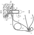
図4〜図7に示すように、インナパネル3の車内側はトップシーリング(車体内装材)11で覆われている。また、取付孔5の上辺部には、車外に向かって直角に折り曲げられた折曲部3aが形成されている。インナパネル3の車外側には、中間パネル13及びアウタパネル15が配設され、各パネル11,13,15は取付孔5から下側に離れた位置で溶接によって一体となっている。この溶接部分にウェザストリップ17が取り付けられ、トップシーリング11下端部がウェザストリップ17によって支持されている。インナパネル3下端部は車外側に湾曲しており、この湾曲部分とトップシーリング11との間の空間にエアバッグ19が配設されている。
As shown in FIGS. 4 to 7, the inner side of the
次に、取付座7及びロック部材9の構成について説明する。
Next, the configuration of the mounting
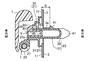
取付座7は、樹脂製であって、図2に示すように、取付座本体21と、取付座本体21から裏面側に突出し、可撓性を有するU字状の係止片23とを備えている。取付座本体21中央部には、ロック部材9が取り付けられるロック部材取付部25が設けられている。ロック部材取付部25下端部には、グリップ本体11を軸支する軸支部29が設けられ、この軸支部29に軸27(図1参照)が挿通される挿通孔29aが貫通形成されている。さらに、ロック部材取付部25裏面側には、フランジ部31が形成されている。ロック部材取付部25には表面側から裏面側に貫通形成された馬蹄状の開口部25aが形成されており、この開口部25aを囲むように内周壁部33及び外周壁部35が設けられている。外周壁部35は、フランジ部31から表面側に一体に突設され、内周壁部33は、この外周壁部33から表面側に一体に突設されている。係止片23は、開口部25a下辺よりも幅狭であって、その一端37aが内周壁部25内周面に一体形成され、ロック部材取付部25から裏面側に延出する延出部37と、延出部37の延出端から表面側に折り返され、折返端が自由端を構成する折返部39とを有し、さらに折返部39の中途部には係止突起41が突設されている。係止突起41は、側方視略直角三角形状であって、裏面側に行くに従って下がるように傾斜する裏面側端面41a及び垂直な表面側端面41bが形成されている。また、折返端部39aには矩形状の嵌込孔39bが上下方向に貫通形成され、この嵌込孔39bにロック部材9の後述する突起45bが嵌め込まれる。この嵌込孔39bよりも表面側の下面39cは、表面側に行くに従って上方に傾斜している。
As shown in FIG. 2, the mounting
ロック部材9は、樹脂製であって、上記開口部25aを覆う蓋部43と、蓋部43から裏面側に延出する上下に離間した一対の水平な支持片部(支持部)45,46と、支持片部45,46の幅方向両側に設けられ、蓋部43から裏面側に突出するガイド片部(ガイド部)47とを一体に有している。蓋部43は、開口部25aと略同一形状の縦板部49と、縦板部49周縁から裏面側に延出し、頂部に裏面側に開口する切欠部51aが形成された側板部51とを有している。支持片部45,46は、上記係止片23と同一幅の矩形状であって、表面側端が縦板部49に繋がる一方、左右両端がガイド片部47の左右方向内側面に繋がっている。図4に示すように、上側支持片部45の延出端上面45aは裏面側に行くに従って下方に傾斜している一方、下側支持片部46の延出端下面46aは裏面側に行くに従って上方に傾斜している。さらに、上側支持片部45には側方視台形状の突起45bが突設されている。また、ガイド片部47の延出端部は裏面側ほど細くなっている。
The
ロック部材9は取付座7の表面側から組み付けられる。具体的には、先ず、両ガイド片部47を開口部25a内の係止片23両側にそれぞれ挿入し、両支持片部45,46を係止片23両端にそれぞれ当接させる。このとき、上側支持片部45の突起45bが係止片23の折返端部39aに当接すると、可撓性を有する折返部39が撓んで折返端部39aが突起45bに乗り上げ、突起45bが嵌込孔39bまで移動すると、折返部39が復帰し、突起45bが嵌込孔39bに嵌め込まれる。そして、蓋部43の側板部51端面が取付座7の外周壁部35端面に当接し、図3に示すように、ロック部材9が取付座7に組み付けられる。この組付状態で、上側支持片部45は折返端部39aを延出部37側から支持する一方、ガイド片部突出端47aが係止片突出端23aよりも裏面側に突出している。また、この組付状態で、取付座7のフランジ部31と係止片23の係止突起41との間隔Dは、インナパネル3の折曲部3aの延出寸法とほぼ一致している。そして、この組付状態で、折返端部39aが表面側に押された場合に、嵌込孔39b内の突起45bが折返端部39aを裏面側に押すことによって取付座本体21と係止突起41との間隔Dが一定に保持される。したがって、突起45b及び嵌込孔39bは、間隔Dを一定に保持する間隔保持手段を構成している。
The
次に、アシストグリップGをインナパネル3に取り付ける手順について説明する。
Next, a procedure for attaching the assist grip G to the
先ず、予めロック部材9が組み付けられた一対の取付座7、一対の軸27及びグリップ本体1を用意し、グリップ本体1の両端にそれぞれ取付座7を取り付け、アシストグリップGを組み立てる。次に、両取付座7の各ガイド片部延出端47aを各取付孔5に挿入し、ロック部材9を取付座7に押さえ付けながら車外側に押し込む。この過程で、先ず、係止突起41の裏面側端面41aが取付孔5上辺部に当接し、当該裏面側端面41aの傾斜に沿って係止突起41が下方に押される。すると、係止突起41が支持片部45,46から離れているので、可撓性を有する折返部39は支持片部45,46に妨げられることなく下側(すなわち延出部37側)に撓み、係止突起41が折曲部3a下側に移動する。続いて、折返部39が復帰しようするため、係止突起41が上側に押され、折曲部3aに摺接しながら車外側に移動する。このとき、係止突起41は、折曲部3aとの間に摩擦が生じてその場に止まろうとするが、間隔保持手段である突起45b及び嵌込孔39bによって取付座本体21と係止突起41との間の間隔Dが一定に保持され、係止突起41が車外側に押される。そして、係止突起41が折曲部3aに摺接しながら通過すると、折返部39が復帰し、係止突起41が折曲部3aの端部に車外側から当接する一方、取付座本体21のフランジ部31が取付孔5周縁部に車内側から当接することにより、取付座7がインナパネル3に固定される。
First, a pair of mounting
このように、アシストグリップGを取り付ける際には、予めロック部材9を組み付けた取付座7を取付孔5に挿入するだけなので、アシストグリップGの取り付けが簡単である。また、取付座7を取付孔5に挿入する際に、取付座7裏面側が取付座本体21で隠れている場合、取付座7を傾けて挿入端を視認しながら挿入するが、ガイド片部突出端47aが係止片延出端23aよりも裏面側に突出しているので、挿入端であるガイド片部突出端47aを、取付座7を比較的浅い角度傾けるだけで視認できる。したがって、アシストグリップGの取付作業性が向上する。さらに、係止片23を取付孔5に挿入する際に、突起45b及び嵌込孔39bによって構成された間隔保持手段が、係止突起41と取付座本体21との間の間隔Dを一定に保持することにより、係止突起41が折曲部3aとの間で生じる摩擦に抗して車外側に押され、折曲部3aを通過することができるため、係止突起41の係止不良を防ぐことができる。
Thus, when the assist grip G is attached, the
一方、アシストグリップGがインナパネル3に取り付けられた状態で、ガイド片部47が取付孔5の上下両周縁部に当接しているので、アシストグリップG使用時にグリップ本体1を下方に引っ張っても、ガイド片部47が取付孔5周縁部につっかえ、取付座7の移動を規制するため、アシストグリップG使用時のぐらつきを抑えるとともに、取付座7の取付孔5からの脱落がさらに規制される。また、この状態から図6に示すように取付孔5下側のエアバッグ19が展開すると、トップシーリング11下端のウェザストリップ17による支持状態が解除されてトップシーリング11が車内側に捲れ上がり、取付座本体21がトップシーリング11によって車内側に押されるが、係止突起41がエアバッグ19とは反対側の折返部39のみに設けられているため、取付座7がエアバッグ19の展開圧力を受けても、係止片23が係止突起41と取付孔5周縁部との当接部を支点として取付孔5内を移動することによって展開圧力が軽減し、取付座7の破損やアシストグリップGの車内側への飛び出しを防ぐことができる。さらに、取付孔5周縁部に車外側に折り曲げられた折曲部3aが形成されているので、係止突起41を車外側にずらして取付座7の車内側への突出を抑制することができ、見栄えが向上する。
On the other hand, since the
取付座7を取り外す際には、図7に示すように、グリップ本体1を押し下げた状態で側板部51頂部の切欠部51aに例えばマイナスドライバ55を差し込み、その先端55aを折返端部39aとロック部材9の上側支持片部45との間に入れて折返端部39aを持ち上げ、突起45bを嵌込孔39bから外し、ロック部材9を車内側に引っ張って取り外す。次に、係止片23の折返端部39aを下方に押して係止状態を解除し、そのまま取付座7を車内側に引っ張る。これにより、取付座7が取り外される。
When removing the mounting
(実施形態2)
実施形態1では、係止突起41が折返部39だけに設けられていたが、延出部37及び折返部39の両方に設けられてもよい。すなわち、図8に示すように、延出部37に係止突起57が突設されている。そして、一対の係止突起41,57は、取付孔5周縁部の上下両側において車外側から当接して延出部37及び折返部39双方の車内側への移動を規制している。したがって、上側の係止突起41のみが当接する上記実施形態1と比較して、より確実に取付座7が取付孔5から脱落するのを規制することができる。
(Embodiment 2)
In the first embodiment, the locking
(実施形態3)
実施形態1,2では、間隔保持手段が折返端部39aの嵌込孔39b及び上側支持片部45の突起45bで構成されていた。しかしながら、取付座7及びロック部材9双方にそれぞれ上記嵌込孔39b及び突起45bを設けなければならないため、製造に手間がかかる。そこで、本実施形態では、ロック部材9の構造を変更し、より簡単な構造で間隔保持手段が構成されている。
(Embodiment 3)
In the first and second embodiments, the interval holding means is configured by the
すなわち、図9に示すように、ロック部材9の蓋部59は、上側支持片部45、縦板部61及び側板部63に囲まれ、且つ裏面側端面が垂直な縦壁部65とを有している。尚、ロック部材9以外の構成は、実施形態1と同じである。
That is, as shown in FIG. 9, the lid portion 59 of the
そして、ロック部材9が取付座7に組み付けられた状態で、側板部63の裏面側端面が外周壁部35の表面側端面に当接する一方、縦壁部65が係止片23の折返端部39aに当接している。そうすると、ロック部材9が組み付けられた取付座7を取付孔5に挿入する過程で、係止突起41が折曲部3aに摺接することにより折返端部39aがその場に止まろうとするが、折返端部39aが縦壁部65に当接して車外側に押され、それによって係止突起41が折曲部3aを通過する。このように、縦壁部65をロック部材9に設けるだけで間隔保持手段を構成することができる。したがって、製造の手間を減らすことができる。
In the state where the
(実施形態4)
上記実施形態1〜3では、係止片23が樹脂で構成されていた。しかしながら、取付座7にエアバッグ19の展開圧力等の高負荷がかかると、樹脂製の係止片23が破損する虞がある。また、係止片23の一部である係止突起41が金属製のインナパネル3に常時当接することによって削られてしまい、係止突起41と折曲部3aの端部との間に隙間ができて、取付座7がガタつき、異音が発生する虞もある。
(Embodiment 4)
In the first to third embodiments, the locking
そこで、本実施形態では、図10、11に示すように、係止片67を金属で構成する。係止片67は、上記係止片23と同様にU字状であって、延出部69の一端69aが該一端69aから左右両側に延びる側部69bによって内周壁部25両側部に係止され、折返端が自由端である折返部71は、折返端部71aに略矩形状の嵌込孔71bが上下方向に貫通形成されている。さらに、折返部71の中途部には、側方視直角三角形状に折り曲げられた係止突起73が設けられている。係止突起73の裏面側端面73aは裏面側に行くに従って下がるように傾斜し、表面側端面73bは垂直になっている。尚、係止片67以外の構成は、実施形態1と同じである。また、取付座本体21は、樹脂製であって、係止片67と別体である。
Therefore, in the present embodiment, as shown in FIGS. 10 and 11, the locking
そうして、ロック部材9が組み付けられた取付座7を取付孔5に挿入する過程で、係止突起73の裏面側端面73aが取付孔5周縁部に当接して係止突起73が下方に押され、折返部71が下側に撓むとともに、係止突起73自身もその下方の貫通孔73c内に入り込む。そして、係止突起73が折曲部3aを通過すると係止突起73及び折返部71が復帰し、取付座7のフランジ部31が取付孔5周縁部に車内側から当接する一方、係止突起73の表面側端面73bが折曲部3a端部に車外側から当接することによって取付座7がインナパネル3に固定される。
Then, in the process of inserting the mounting
このように、係止片67が樹脂よりも強度が大きい金属で構成されているため、樹脂製の場合と比べて破損する虞が軽減する。さらに、インナパネル3と同じ金属製であるため、インナパネル3と常時当接しても削られ難い。したがって、取付座7のガタつきや異音発生を抑制することができる。
Thus, since the locking
本発明は、実施形態に限定されず、その精神又は主要な特徴から逸脱することなく他の色々な形で実施することができる。 The present invention is not limited to the embodiments, and can be implemented in various other forms without departing from the spirit or main features thereof.
上記実施形態では、一対の支持片部45,46が矩形板状であったが、これに限定されず、折返端部39a,71aを下側から支持できるものであればよい。例えば、ブロック状のものであってもよい。
In the said embodiment, although a pair of
また、上記実施形態では、ガイド片部47が略矩形板状であったが、これに限定されず、例えば、棒状のものであってもよい。
Moreover, in the said embodiment, although the
このように、上述の実施形態はあらゆる点で単なる例示に過ぎず、限定的に解釈してはならない。本発明の範囲は特許請求の範囲によって示すものであって、明細書には何ら拘束されない。さらに、特許請求の範囲の均等範囲に属する変形や変更は、全て本発明の範囲内のものである。 As described above, the above-described embodiment is merely an example in all respects and should not be interpreted in a limited manner. The scope of the present invention is defined by the claims, and is not limited by the specification. Further, all modifications and changes belonging to the equivalent scope of the claims are within the scope of the present invention.
以上説明したように、本発明に係るアシストグリップの取付構造は、アシストグリップを取り付ける手間を減らす用途等に適用することができる。 As described above, the assist grip mounting structure according to the present invention can be applied to a purpose of reducing the labor of attaching the assist grip.
1 グリップ本体
3 インナパネル(車体パネル)
3a 折曲部
5 取付孔
7 取付座
9 ロック部材
11 トップシーリング(車体内装材)
19 エアバッグ
21 取付座本体
23,67 係止片
25a 開口部
37,69 延出部
39,71 折返部
39b,71b 嵌込孔(間隔保持手段)
41,57,73 係止突起
45,46 支持片部(支持部)
45b 突起(間隔保持手段)
47 ガイド片部(ガイド部)
65 縦壁部(間隔保持手段)
G アシストグリップ
1
3a
19
41, 57, 73
45b Protrusion (interval holding means)
47 Guide piece (guide part)
65 Vertical wall (interval holding means)
G assist grip
Claims (7)
上記取付座(7)は、開口部(25a)を有する取付座本体(21)と、該取付座本体(21)の裏面側に突出する可撓性を有するU字形状の係止片(23,67)とを有し、
上記係止片(23,67)は、上記取付座本体(21)から裏面側に延出する延出部(37,69)と、該延出部(37,69)の延出端から折り返され、折返端が自由端を構成する折返部(39,71)とを有し、該延出部(37,69)及び折返部(39,71)の少なくとも一方の中途部に係止突起(41,57,73)が形成され、
上記ロック部材(9)は、上記取付座本体(21)の開口部(25a)に表面側から挿入された状態で、上記折返部(39)の折返端部(39a)を上記延出部(37)側から支持する支持部(45,46)を有し、
上記支持部(45,46)を上記取付座本体(21)の開口部(25a)に表面側から挿入して上記ロック部材(9)を上記取付座(7)に組み付けた状態から上記係止片(23,67)を上記取付孔(5)に挿入する過程で、上記係止突起(41,57,63)が取付孔(5)周縁部に摺接することで上記折返部(39,71)が上記延出部(37,69)側に撓み、かつ取付孔(5)周縁部を通過することで上記折返部(39,71)が復帰して、上記係止突起(41,57,63)が取付孔(5)周縁部に車外側から当接するとともに、上記取付座本体(21)が取付孔(5)周縁部に車内側から当接するように構成されていることを特徴とするアシストグリップの取付構造。 The grip body (1) and the grip body (1) are provided at both ends of the grip body (1) and inserted into the substantially rectangular mounting holes (5) of the vehicle body panel (3) from the inside of the vehicle so that the grip body (1) is An assist grip mounting structure comprising a pair of mounting seats (7) to be mounted on the panel (3) and a lock member (9) for restricting the mounting seats (7) from falling off the mounting holes (5). There,
The mounting seat (7) includes a mounting seat main body (21) having an opening (25a) and a flexible U-shaped locking piece (23) protruding to the back side of the mounting seat main body (21). , 67)
The locking pieces (23, 67) are folded back from the extending portion (37, 69) extending from the mounting seat body (21) to the back side and the extending end of the extending portion (37, 69). And the folded end has a folded portion (39, 71) that constitutes a free end, and a locking projection (30) is provided at a middle portion of at least one of the extended portion (37, 69) and the folded portion (39, 71). 41,57,73) are formed,
The lock member (9) is inserted into the opening (25a) of the mounting seat body (21) from the surface side, and the folded end (39a) of the folded portion (39) is connected to the extended portion ( 37) having a support part (45, 46) that supports from the side,
The support portion (45, 46) is inserted into the opening (25a) of the mounting seat main body (21) from the surface side, and the locking member (9) is assembled to the mounting seat (7) from the state where the locking is performed. In the process of inserting the piece (23, 67) into the mounting hole (5), the locking protrusion (41, 57, 63) is in sliding contact with the peripheral edge of the mounting hole (5), so that the folded portion (39, 71). ) Bends toward the extended portion (37, 69) and passes through the peripheral edge of the mounting hole (5), the folded portion (39, 71) returns, and the locking projection (41, 57, 63) contacts the mounting hole (5) peripheral portion from the vehicle outer side, and the mounting seat body (21) contacts the mounting hole (5) peripheral portion from the vehicle inner side. Assist grip mounting structure.
上記ロック部材(9)は、裏面側に延出して上記取付座本体(21)の開口部(25a)に表面側から挿入されるガイド部(47)をさらに有し、
上記ガイド部(47)は、上記取付座本体(21)の開口部(25a)に表面側から挿入して上記ロック部材(9)を上記取付座(7)に組み付けて上記取付孔(5)に挿入された状態で、取付孔(5)周縁部に当接していることを特徴とするアシストグリップの取付構造。 The assist grip mounting structure according to claim 1,
The lock member (9) further includes a guide portion (47) extending from the front surface side to the opening portion (25a) of the mounting seat body (21) extending to the back surface side,
The guide portion (47) is inserted into the opening (25a) of the mounting seat body (21) from the surface side, and the locking member (9) is assembled to the mounting seat (7) to mount the mounting hole (5). An assist grip mounting structure, wherein the mounting structure is in contact with the peripheral edge of the mounting hole (5) in a state of being inserted into the mounting hole.
上記ガイド部(47)は、上記取付座本体(21)の開口部(25a)に表面側から挿入して上記ロック部材(9)を上記取付座(7)に組み付けた状態で、その先端(47a)が上記係止片突出端(23a)よりも裏面側に突出していることを特徴とするアシストグリップの取付構造。 In the assist grip mounting structure according to claim 2,
The guide portion (47) is inserted into the opening (25a) of the mounting seat main body (21) from the surface side and the lock member (9) is assembled to the mounting seat (7), with its tip ( 47a) An assist grip mounting structure characterized in that 47a) protrudes further toward the back side than the locking piece protruding end (23a).
上記支持部(45,46)を上記取付座本体(21)の開口部(25a)に表面側から挿入して上記ロック部材(9)を上記取付座(7)に組み付けた状態から上記係止片(23,67)を取付孔(5)に挿入する過程で、該係止突起(41,63)と上記取付座本体(21)との間隔(D)を一定に保持する間隔保持手段(39b,45b,65,71b)をさらに備えることを特徴とするアシストグリップの取付構造。 The assist grip mounting structure according to any one of claims 1 to 3,
The support portion (45, 46) is inserted into the opening (25a) of the mounting seat main body (21) from the surface side, and the locking member (9) is assembled to the mounting seat (7) from the state where the locking is performed. In the process of inserting the piece (23, 67) into the mounting hole (5), a distance holding means for maintaining a constant distance (D) between the locking projection (41, 63) and the mounting seat body (21) ( 39b, 45b, 65, 71b), further comprising an assist grip mounting structure.
上記取付孔(5)周縁部の車内側は、車体内装材(11)によって覆われ、
上記取付座(7)は、上記係止片(23,67)が取付孔(5)に挿入された状態で、上記車体内装材(11)を介して上記車体パネル(3)に車内側から当接し、
上記取付孔(5)の上記延出部(37)側及び折返部(39)側の一方における上記車体内装材(11)と車体パネル(3)との間の空間にエアバッグ(19)が配設され、
上記係止突起(41)は、上記延出部(37)及び折返部(39)の他方のみに形成されていることを特徴とするアシストグリップの取付構造。 In the assist grip mounting structure according to any one of claims 1 to 4,
The inside of the mounting hole (5) peripheral edge is covered with the vehicle interior material (11),
The mounting seat (7) is connected to the vehicle body panel (3) from the vehicle interior side through the vehicle interior material (11) with the locking pieces (23, 67) being inserted into the mounting holes (5). Abut,
An airbag (19) is disposed in a space between the vehicle interior material (11) and the vehicle body panel (3) on one of the extension part (37) side and the folded part (39) side of the mounting hole (5). Arranged,
The assist grip mounting structure, wherein the locking protrusion (41) is formed only on the other of the extending portion (37) and the folded portion (39).
上記取付座本体(21)は、樹脂で構成され、
上記係止片(67)は、金属で構成されていることを特徴とするアシストグリップの取付構造。 In the assist grip mounting structure according to any one of claims 1 to 5,
The mounting seat body (21) is made of resin,
The assist grip mounting structure, wherein the locking piece (67) is made of metal.
上記取付孔(5)周縁部には、車外に向かって折り曲げられた折曲部(3a)が形成され、
上記係止突起(41,73)は、上記係止片(23,67)が取付孔(5)に挿入された状態で、上記折曲部(3a)の端部に車外側から当接することを特徴とするアシストグリップの取付構造。 The assist grip mounting structure according to any one of claims 1 to 6,
A bent portion (3a) that is bent toward the outside of the vehicle is formed on the periphery of the mounting hole (5),
The locking projections (41, 73) are brought into contact with the end of the bent portion (3a) from the outside of the vehicle with the locking pieces (23, 67) inserted into the mounting holes (5). Assist grip mounting structure characterized by
Priority Applications (1)
| Application Number | Priority Date | Filing Date | Title |
|---|---|---|---|
| JP2012017487A JP2013154792A (en) | 2012-01-31 | 2012-01-31 | Mounting structure of assist grip |
Applications Claiming Priority (1)
| Application Number | Priority Date | Filing Date | Title |
|---|---|---|---|
| JP2012017487A JP2013154792A (en) | 2012-01-31 | 2012-01-31 | Mounting structure of assist grip |
Publications (1)
| Publication Number | Publication Date |
|---|---|
| JP2013154792A true JP2013154792A (en) | 2013-08-15 |
Family
ID=49050424
Family Applications (1)
| Application Number | Title | Priority Date | Filing Date |
|---|---|---|---|
| JP2012017487A Pending JP2013154792A (en) | 2012-01-31 | 2012-01-31 | Mounting structure of assist grip |
Country Status (1)
| Country | Link |
|---|---|
| JP (1) | JP2013154792A (en) |
Cited By (1)
| Publication number | Priority date | Publication date | Assignee | Title |
|---|---|---|---|---|
| CN114960133A (en) * | 2021-02-19 | 2022-08-30 | 夏普株式会社 | Washing machine |
-
2012
- 2012-01-31 JP JP2012017487A patent/JP2013154792A/en active Pending
Cited By (1)
| Publication number | Priority date | Publication date | Assignee | Title |
|---|---|---|---|---|
| CN114960133A (en) * | 2021-02-19 | 2022-08-30 | 夏普株式会社 | Washing machine |
Similar Documents
| Publication | Publication Date | Title |
|---|---|---|
| JP5287129B2 (en) | Vehicle seat slide device | |
| JP5661696B2 (en) | Vehicle seat device | |
| JP2007186104A (en) | Vehicle slide rail structure | |
| JP2009184615A (en) | Vehicle seat table | |
| JP4373969B2 (en) | Harness clip | |
| JPWO2014199939A1 (en) | Mounting structure for vehicle door lining | |
| JP6124133B2 (en) | connector | |
| JP6002327B2 (en) | Reinforcing leaf spring for plastic clips | |
| JP6722501B2 (en) | Resin cover and vehicle seat equipped with resin cover | |
| JP6031185B2 (en) | Vehicle seat | |
| JP2018058576A (en) | Seat slide device | |
| JP2009029328A (en) | Trim clip suitable for trim for curtain side air bag | |
| JP5307936B2 (en) | Mounting member mounting structure | |
| JP6477060B2 (en) | Knee bolster | |
| JP2013154792A (en) | Mounting structure of assist grip | |
| JP5911023B2 (en) | Resin member mounting structure | |
| JP2018052401A (en) | Seat slide device | |
| JP2019006380A (en) | Headrest | |
| WO2019082881A1 (en) | Mounting structure of automotive parts | |
| JP2015202783A (en) | Pillar garnish installation structure | |
| JPWO2017094575A1 (en) | Hook device | |
| JP5353493B2 (en) | Undercover structure for vehicle seats | |
| JP6315186B2 (en) | Pull pocket mounting structure | |
| JP2007137363A (en) | Cowl louva | |
| JP7406954B2 (en) | Installation device for vehicle interior parts |