JP2013198217A - 電気設備用架台 - Google Patents
電気設備用架台 Download PDFInfo
- Publication number
- JP2013198217A JP2013198217A JP2012060815A JP2012060815A JP2013198217A JP 2013198217 A JP2013198217 A JP 2013198217A JP 2012060815 A JP2012060815 A JP 2012060815A JP 2012060815 A JP2012060815 A JP 2012060815A JP 2013198217 A JP2013198217 A JP 2013198217A
- Authority
- JP
- Japan
- Prior art keywords
- main body
- electrical equipment
- plate
- lid
- distribution system
- Prior art date
- Legal status (The legal status is an assumption and is not a legal conclusion. Google has not performed a legal analysis and makes no representation as to the accuracy of the status listed.)
- Granted
Links
Images


Landscapes
- Patch Boards (AREA)
Abstract
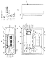
【解決手段】架台1は、配電系機器4,5が取り付けられる取付部材を備え、本体2の天面には配電系機器4,5と電気設備100を電気的に接続するための電線が挿通される挿通孔(窓孔23)が設けられている。そのため、本体2内の空いたスペースを有効活用することにより、配電系機器4,5の設置スペースの削減を図ることができる。
【選択図】 図1
Description
2 本体
3 蓋体
4 トランス(配電系機器)
5 ブレーカ(配電系機器)
23 窓孔(挿通孔)
60 台座
61 固定片
70 取付板
71 支持部材
Claims (4)
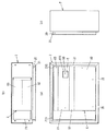
- 前面が開口した箱形の本体と、前記本体の前面開口を開閉自在に塞ぐ蓋体と、前記本体内に設けられ、配電系の機器が取り付けられる取付部材とを備え、前記本体は、電気設備が載置される天面に、前記配電系機器と前記電気設備を電気的に接続するための電線が挿通される挿通孔が設けられることを特徴とする電気設備用架台。
- 前記本体又は蓋体の少なくとも何れか一方の下部に通気孔が設けられ、前記本体の天面には、前記電気設備の底面に設けられている通気孔と対向する貫通孔が設けられることを特徴とする請求項1記載の電気設備用架台。
- 前記本体は、前面下部に被係止部が設けられ、前記蓋体は、前記被係止部に回動自在に係止する係止部が下部に設けられることを特徴とする請求項1又は2記載の電気設備用架台。
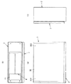
- 前記配電系機器を覆うカバーを備え、前記カバーは、前記本体の天面に対向する面が下向きに傾斜する傾斜面となっていることを特徴とする請求項1〜3の何れか1項に記載の電気設備用架台。
Priority Applications (1)
| Application Number | Priority Date | Filing Date | Title |
|---|---|---|---|
| JP2012060815A JP5906414B2 (ja) | 2012-03-16 | 2012-03-16 | 設備 |
Applications Claiming Priority (1)
| Application Number | Priority Date | Filing Date | Title |
|---|---|---|---|
| JP2012060815A JP5906414B2 (ja) | 2012-03-16 | 2012-03-16 | 設備 |
Related Child Applications (1)
| Application Number | Title | Priority Date | Filing Date |
|---|---|---|---|
| JP2016000682A Division JP6175734B2 (ja) | 2016-01-05 | 2016-01-05 | 設備 |
Publications (2)
| Publication Number | Publication Date |
|---|---|
| JP2013198217A true JP2013198217A (ja) | 2013-09-30 |
| JP5906414B2 JP5906414B2 (ja) | 2016-04-20 |
Family
ID=49396543
Family Applications (1)
| Application Number | Title | Priority Date | Filing Date |
|---|---|---|---|
| JP2012060815A Active JP5906414B2 (ja) | 2012-03-16 | 2012-03-16 | 設備 |
Country Status (1)
| Country | Link |
|---|---|
| JP (1) | JP5906414B2 (ja) |
Cited By (1)
| Publication number | Priority date | Publication date | Assignee | Title |
|---|---|---|---|---|
| EP3128575A4 (en) * | 2014-03-31 | 2017-10-18 | Nec Corporation | Rechargeable-battery device |
Citations (8)
| Publication number | Priority date | Publication date | Assignee | Title |
|---|---|---|---|---|
| JPS58184471U (ja) * | 1982-05-31 | 1983-12-08 | 三菱電機株式会社 | 操作盤用開戸の開閉装置 |
| JPS60147906U (ja) * | 1984-03-10 | 1985-10-01 | 株式会社明電舎 | 屋外盤 |
| JPS62191302U (ja) * | 1986-05-23 | 1987-12-05 | ||
| JPH0480211U (ja) * | 1990-11-26 | 1992-07-13 | ||
| JPH06217424A (ja) * | 1993-01-14 | 1994-08-05 | Hitachi Cable Ltd | 電気機器収納箱 |
| US6362951B1 (en) * | 1997-11-24 | 2002-03-26 | Nec Corporation | Container for use in a communication apparatus having a plurality from one another in waterproof level of independent chambers which are different |
| JP2004022317A (ja) * | 2002-06-14 | 2004-01-22 | Panasonic Ev Energy Co Ltd | 無停電電源装置 |
| JP2012009311A (ja) * | 2010-06-25 | 2012-01-12 | Sanyo Electric Co Ltd | 蓄電システム |
-
2012
- 2012-03-16 JP JP2012060815A patent/JP5906414B2/ja active Active
Patent Citations (8)
| Publication number | Priority date | Publication date | Assignee | Title |
|---|---|---|---|---|
| JPS58184471U (ja) * | 1982-05-31 | 1983-12-08 | 三菱電機株式会社 | 操作盤用開戸の開閉装置 |
| JPS60147906U (ja) * | 1984-03-10 | 1985-10-01 | 株式会社明電舎 | 屋外盤 |
| JPS62191302U (ja) * | 1986-05-23 | 1987-12-05 | ||
| JPH0480211U (ja) * | 1990-11-26 | 1992-07-13 | ||
| JPH06217424A (ja) * | 1993-01-14 | 1994-08-05 | Hitachi Cable Ltd | 電気機器収納箱 |
| US6362951B1 (en) * | 1997-11-24 | 2002-03-26 | Nec Corporation | Container for use in a communication apparatus having a plurality from one another in waterproof level of independent chambers which are different |
| JP2004022317A (ja) * | 2002-06-14 | 2004-01-22 | Panasonic Ev Energy Co Ltd | 無停電電源装置 |
| JP2012009311A (ja) * | 2010-06-25 | 2012-01-12 | Sanyo Electric Co Ltd | 蓄電システム |
Cited By (1)
| Publication number | Priority date | Publication date | Assignee | Title |
|---|---|---|---|---|
| EP3128575A4 (en) * | 2014-03-31 | 2017-10-18 | Nec Corporation | Rechargeable-battery device |
Also Published As
| Publication number | Publication date |
|---|---|
| JP5906414B2 (ja) | 2016-04-20 |
Similar Documents
| Publication | Publication Date | Title |
|---|---|---|
| JP5632071B1 (ja) | 電力貯蔵装置 | |
| JP6182427B2 (ja) | 配電盤 | |
| CN204424192U (zh) | 断路器 | |
| KR101230072B1 (ko) | 수배전반 | |
| JP6460527B2 (ja) | 屋外設置用電気機器 | |
| JP6175734B2 (ja) | 設備 | |
| JP5000013B2 (ja) | 電子機器収容ユニット | |
| CN107069446A (zh) | 一种户外集防雨和高效散热的配电箱 | |
| JP5906414B2 (ja) | 設備 | |
| JP2017103837A (ja) | 電力変換装置 | |
| WO2012169082A1 (ja) | スイッチギヤ | |
| KR101293530B1 (ko) | 슬라이딩 개폐형 도어가 구비된 세대용 통신단자 일체형 분전함 | |
| GB2494896A (en) | Device for retaining and charging rechargeable batteries incorporated into a pattress or wall/junction box. | |
| JP2019176534A (ja) | 蓄電池システム | |
| JP6233747B2 (ja) | 固定部材 | |
| KR101161714B1 (ko) | 안전커버가 구비된 차단기 받침대 | |
| CN201946892U (zh) | 优化型端子箱 | |
| JP5305455B2 (ja) | 電気機器収納用箱 | |
| JP6191958B2 (ja) | 設備機器用筐体、及びこれを備える設備機器 | |
| JP6635364B2 (ja) | 集電箱 | |
| JP4683462B2 (ja) | 冷却用空気を整流する遮蔽体付きスイッチギヤ | |
| CN203180376U (zh) | 一种耐高温耐腐蚀配电箱 | |
| CN207282976U (zh) | 一种配电箱用辅助装置及配电箱 | |
| JP2017229173A (ja) | 系統連系用装置及び配電盤 | |
| CN221885700U (zh) | 一种户外型电气控制柜 |
Legal Events
| Date | Code | Title | Description |
|---|---|---|---|
| A621 | Written request for application examination |
Free format text: JAPANESE INTERMEDIATE CODE: A621 Effective date: 20141208 |
|
| A711 | Notification of change in applicant |
Free format text: JAPANESE INTERMEDIATE CODE: A711 Effective date: 20150123 |
|
| A977 | Report on retrieval |
Free format text: JAPANESE INTERMEDIATE CODE: A971007 Effective date: 20150904 |
|
| A131 | Notification of reasons for refusal |
Free format text: JAPANESE INTERMEDIATE CODE: A131 Effective date: 20150908 |
|
| A521 | Written amendment |
Free format text: JAPANESE INTERMEDIATE CODE: A523 Effective date: 20151109 |
|
| TRDD | Decision of grant or rejection written | ||
| A01 | Written decision to grant a patent or to grant a registration (utility model) |
Free format text: JAPANESE INTERMEDIATE CODE: A01 Effective date: 20151208 |
|
| A61 | First payment of annual fees (during grant procedure) |
Free format text: JAPANESE INTERMEDIATE CODE: A61 Effective date: 20160106 |
|
| R151 | Written notification of patent or utility model registration |
Ref document number: 5906414 Country of ref document: JP Free format text: JAPANESE INTERMEDIATE CODE: R151 |