JP2013242590A - Uv inkjet printing of vision control panel - Google Patents
Uv inkjet printing of vision control panel Download PDFInfo
- Publication number
- JP2013242590A JP2013242590A JP2013150549A JP2013150549A JP2013242590A JP 2013242590 A JP2013242590 A JP 2013242590A JP 2013150549 A JP2013150549 A JP 2013150549A JP 2013150549 A JP2013150549 A JP 2013150549A JP 2013242590 A JP2013242590 A JP 2013242590A
- Authority
- JP
- Japan
- Prior art keywords
- panel
- design
- ink
- layer
- printed
- Prior art date
- Legal status (The legal status is an assumption and is not a legal conclusion. Google has not performed a legal analysis and makes no representation as to the accuracy of the status listed.)
- Pending
Links
- 238000007641 inkjet printing Methods 0.000 title abstract description 19
- 230000004438 eyesight Effects 0.000 title abstract description 4
- 238000013461 design Methods 0.000 claims abstract description 205
- 238000000034 method Methods 0.000 claims abstract description 164
- 239000000463 material Substances 0.000 claims abstract description 73
- 239000000976 ink Substances 0.000 claims description 188
- 238000007639 printing Methods 0.000 claims description 183
- 230000008569 process Effects 0.000 claims description 35
- 238000004519 manufacturing process Methods 0.000 claims description 19
- 238000002834 transmittance Methods 0.000 claims description 4
- 230000000007 visual effect Effects 0.000 abstract description 54
- 239000010410 layer Substances 0.000 description 349
- 230000033001 locomotion Effects 0.000 description 40
- 239000000758 substrate Substances 0.000 description 31
- BQCADISMDOOEFD-UHFFFAOYSA-N Silver Chemical compound [Ag] BQCADISMDOOEFD-UHFFFAOYSA-N 0.000 description 17
- 229910052709 silver Inorganic materials 0.000 description 17
- 239000004332 silver Substances 0.000 description 17
- 239000012780 transparent material Substances 0.000 description 15
- 239000003086 colorant Substances 0.000 description 14
- 230000007246 mechanism Effects 0.000 description 13
- 238000000151 deposition Methods 0.000 description 8
- 230000008021 deposition Effects 0.000 description 8
- 238000010304 firing Methods 0.000 description 8
- 238000001723 curing Methods 0.000 description 7
- XLYOFNOQVPJJNP-UHFFFAOYSA-N water Substances O XLYOFNOQVPJJNP-UHFFFAOYSA-N 0.000 description 7
- 230000005540 biological transmission Effects 0.000 description 6
- 238000005286 illumination Methods 0.000 description 6
- 230000000694 effects Effects 0.000 description 5
- 230000003993 interaction Effects 0.000 description 5
- 230000001788 irregular Effects 0.000 description 5
- 239000000047 product Substances 0.000 description 5
- 238000012360 testing method Methods 0.000 description 5
- 238000012546 transfer Methods 0.000 description 5
- 230000008901 benefit Effects 0.000 description 4
- 238000011049 filling Methods 0.000 description 4
- 210000003128 head Anatomy 0.000 description 4
- 229920000515 polycarbonate Polymers 0.000 description 4
- 239000004417 polycarbonate Substances 0.000 description 4
- 229920000728 polyester Polymers 0.000 description 4
- -1 polypropylene Polymers 0.000 description 4
- 239000004800 polyvinyl chloride Substances 0.000 description 4
- 229920000915 polyvinyl chloride Polymers 0.000 description 4
- NIXOWILDQLNWCW-UHFFFAOYSA-N acrylic acid group Chemical group C(C=C)(=O)O NIXOWILDQLNWCW-UHFFFAOYSA-N 0.000 description 3
- 238000003491 array Methods 0.000 description 3
- 230000007547 defect Effects 0.000 description 3
- 238000009826 distribution Methods 0.000 description 3
- 239000011521 glass Substances 0.000 description 3
- 230000006872 improvement Effects 0.000 description 3
- 230000005855 radiation Effects 0.000 description 3
- 239000002904 solvent Substances 0.000 description 3
- PCTMTFRHKVHKIS-BMFZQQSSSA-N (1s,3r,4e,6e,8e,10e,12e,14e,16e,18s,19r,20r,21s,25r,27r,30r,31r,33s,35r,37s,38r)-3-[(2r,3s,4s,5s,6r)-4-amino-3,5-dihydroxy-6-methyloxan-2-yl]oxy-19,25,27,30,31,33,35,37-octahydroxy-18,20,21-trimethyl-23-oxo-22,39-dioxabicyclo[33.3.1]nonatriaconta-4,6,8,10 Chemical compound C1C=C2C[C@@H](OS(O)(=O)=O)CC[C@]2(C)[C@@H]2[C@@H]1[C@@H]1CC[C@H]([C@H](C)CCCC(C)C)[C@@]1(C)CC2.O[C@H]1[C@@H](N)[C@H](O)[C@@H](C)O[C@H]1O[C@H]1/C=C/C=C/C=C/C=C/C=C/C=C/C=C/[C@H](C)[C@@H](O)[C@@H](C)[C@H](C)OC(=O)C[C@H](O)C[C@H](O)CC[C@@H](O)[C@H](O)C[C@H](O)C[C@](O)(C[C@H](O)[C@H]2C(O)=O)O[C@H]2C1 PCTMTFRHKVHKIS-BMFZQQSSSA-N 0.000 description 2
- 239000004743 Polypropylene Substances 0.000 description 2
- GWEVSGVZZGPLCZ-UHFFFAOYSA-N Titan oxide Chemical compound O=[Ti]=O GWEVSGVZZGPLCZ-UHFFFAOYSA-N 0.000 description 2
- 238000010521 absorption reaction Methods 0.000 description 2
- 239000000654 additive Substances 0.000 description 2
- 239000000853 adhesive Substances 0.000 description 2
- 230000001070 adhesive effect Effects 0.000 description 2
- 239000002313 adhesive film Substances 0.000 description 2
- 238000013019 agitation Methods 0.000 description 2
- 238000007605 air drying Methods 0.000 description 2
- 230000000903 blocking effect Effects 0.000 description 2
- 229910052799 carbon Inorganic materials 0.000 description 2
- 230000015556 catabolic process Effects 0.000 description 2
- 125000002091 cationic group Chemical group 0.000 description 2
- 230000008859 change Effects 0.000 description 2
- 239000012141 concentrate Substances 0.000 description 2
- 238000011109 contamination Methods 0.000 description 2
- 238000006731 degradation reaction Methods 0.000 description 2
- 238000001035 drying Methods 0.000 description 2
- 230000009977 dual effect Effects 0.000 description 2
- 238000010438 heat treatment Methods 0.000 description 2
- 230000000670 limiting effect Effects 0.000 description 2
- 230000003287 optical effect Effects 0.000 description 2
- 230000036961 partial effect Effects 0.000 description 2
- 239000002245 particle Substances 0.000 description 2
- 239000000049 pigment Substances 0.000 description 2
- 239000011295 pitch Substances 0.000 description 2
- 239000002985 plastic film Substances 0.000 description 2
- 229920006255 plastic film Polymers 0.000 description 2
- 229920006267 polyester film Polymers 0.000 description 2
- 229920001155 polypropylene Polymers 0.000 description 2
- 230000002829 reductive effect Effects 0.000 description 2
- 238000009877 rendering Methods 0.000 description 2
- 230000002441 reversible effect Effects 0.000 description 2
- 229920006395 saturated elastomer Polymers 0.000 description 2
- 238000007650 screen-printing Methods 0.000 description 2
- 239000002356 single layer Substances 0.000 description 2
- 239000000243 solution Substances 0.000 description 2
- 238000001228 spectrum Methods 0.000 description 2
- 238000009736 wetting Methods 0.000 description 2
- 239000012463 white pigment Substances 0.000 description 2
- 241000139306 Platt Species 0.000 description 1
- 239000004793 Polystyrene Substances 0.000 description 1
- 241001085205 Prenanthella exigua Species 0.000 description 1
- 206010043458 Thirst Diseases 0.000 description 1
- 238000003848 UV Light-Curing Methods 0.000 description 1
- 230000006750 UV protection Effects 0.000 description 1
- 230000009471 action Effects 0.000 description 1
- 230000000996 additive effect Effects 0.000 description 1
- 239000012790 adhesive layer Substances 0.000 description 1
- 125000000129 anionic group Chemical group 0.000 description 1
- 230000009286 beneficial effect Effects 0.000 description 1
- 230000002457 bidirectional effect Effects 0.000 description 1
- 230000000740 bleeding effect Effects 0.000 description 1
- 210000004556 brain Anatomy 0.000 description 1
- 239000006229 carbon black Substances 0.000 description 1
- 238000000576 coating method Methods 0.000 description 1
- 238000004040 coloring Methods 0.000 description 1
- 239000002131 composite material Substances 0.000 description 1
- 239000000470 constituent Substances 0.000 description 1
- 238000012937 correction Methods 0.000 description 1
- 239000013078 crystal Substances 0.000 description 1
- 238000005034 decoration Methods 0.000 description 1
- 238000012938 design process Methods 0.000 description 1
- 238000011161 development Methods 0.000 description 1
- 238000010586 diagram Methods 0.000 description 1
- 239000000975 dye Substances 0.000 description 1
- 238000005516 engineering process Methods 0.000 description 1
- 230000008020 evaporation Effects 0.000 description 1
- 238000001704 evaporation Methods 0.000 description 1
- 239000012467 final product Substances 0.000 description 1
- 230000006870 function Effects 0.000 description 1
- 230000004313 glare Effects 0.000 description 1
- 230000004886 head movement Effects 0.000 description 1
- 238000003384 imaging method Methods 0.000 description 1
- 239000011261 inert gas Substances 0.000 description 1
- 238000002347 injection Methods 0.000 description 1
- 239000007924 injection Substances 0.000 description 1
- 239000007788 liquid Substances 0.000 description 1
- 230000005012 migration Effects 0.000 description 1
- 238000013508 migration Methods 0.000 description 1
- 239000000178 monomer Substances 0.000 description 1
- 239000004033 plastic Substances 0.000 description 1
- 229920003023 plastic Polymers 0.000 description 1
- 229920002223 polystyrene Polymers 0.000 description 1
- 230000004224 protection Effects 0.000 description 1
- 230000009467 reduction Effects 0.000 description 1
- 238000012827 research and development Methods 0.000 description 1
- 239000011347 resin Substances 0.000 description 1
- 229920005989 resin Polymers 0.000 description 1
- 238000000518 rheometry Methods 0.000 description 1
- 238000003756 stirring Methods 0.000 description 1
- 230000036962 time dependent Effects 0.000 description 1
- 239000004408 titanium dioxide Substances 0.000 description 1
- 230000001960 triggered effect Effects 0.000 description 1
- 239000002966 varnish Substances 0.000 description 1
- 238000001429 visible spectrum Methods 0.000 description 1
- 238000009941 weaving Methods 0.000 description 1
- 238000004804 winding Methods 0.000 description 1
- 239000001043 yellow dye Substances 0.000 description 1
Images
































Classifications
-
- B—PERFORMING OPERATIONS; TRANSPORTING
- B41—PRINTING; LINING MACHINES; TYPEWRITERS; STAMPS
- B41M—PRINTING, DUPLICATING, MARKING, OR COPYING PROCESSES; COLOUR PRINTING
- B41M3/00—Printing processes to produce particular kinds of printed work, e.g. patterns
- B41M3/008—Sequential or multiple printing, e.g. on previously printed background; Mirror printing; Recto-verso printing; using a combination of different printing techniques; Printing of patterns visible in reflection and by transparency; by superposing printed artifacts
-
- B—PERFORMING OPERATIONS; TRANSPORTING
- B41—PRINTING; LINING MACHINES; TYPEWRITERS; STAMPS
- B41J—TYPEWRITERS; SELECTIVE PRINTING MECHANISMS, i.e. MECHANISMS PRINTING OTHERWISE THAN FROM A FORME; CORRECTION OF TYPOGRAPHICAL ERRORS
- B41J2/00—Typewriters or selective printing mechanisms characterised by the printing or marking process for which they are designed
- B41J2/005—Typewriters or selective printing mechanisms characterised by the printing or marking process for which they are designed characterised by bringing liquid or particles selectively into contact with a printing material
- B41J2/01—Ink jet
- B41J2/21—Ink jet for multi-colour printing
- B41J2/2107—Ink jet for multi-colour printing characterised by the ink properties
- B41J2/2114—Ejecting specialized liquids, e.g. transparent or processing liquids
- B41J2/2117—Ejecting white liquids
-
- Y—GENERAL TAGGING OF NEW TECHNOLOGICAL DEVELOPMENTS; GENERAL TAGGING OF CROSS-SECTIONAL TECHNOLOGIES SPANNING OVER SEVERAL SECTIONS OF THE IPC; TECHNICAL SUBJECTS COVERED BY FORMER USPC CROSS-REFERENCE ART COLLECTIONS [XRACs] AND DIGESTS
- Y10—TECHNICAL SUBJECTS COVERED BY FORMER USPC
- Y10T—TECHNICAL SUBJECTS COVERED BY FORMER US CLASSIFICATION
- Y10T428/00—Stock material or miscellaneous articles
- Y10T428/24—Structurally defined web or sheet [e.g., overall dimension, etc.]
- Y10T428/24802—Discontinuous or differential coating, impregnation or bond [e.g., artwork, printing, retouched photograph, etc.]
-
- Y—GENERAL TAGGING OF NEW TECHNOLOGICAL DEVELOPMENTS; GENERAL TAGGING OF CROSS-SECTIONAL TECHNOLOGIES SPANNING OVER SEVERAL SECTIONS OF THE IPC; TECHNICAL SUBJECTS COVERED BY FORMER USPC CROSS-REFERENCE ART COLLECTIONS [XRACs] AND DIGESTS
- Y10—TECHNICAL SUBJECTS COVERED BY FORMER USPC
- Y10T—TECHNICAL SUBJECTS COVERED BY FORMER US CLASSIFICATION
- Y10T428/00—Stock material or miscellaneous articles
- Y10T428/24—Structurally defined web or sheet [e.g., overall dimension, etc.]
- Y10T428/24802—Discontinuous or differential coating, impregnation or bond [e.g., artwork, printing, retouched photograph, etc.]
- Y10T428/24851—Intermediate layer is discontinuous or differential
- Y10T428/24868—Translucent outer layer
Landscapes
- Ink Jet (AREA)
- Application Of Or Painting With Fluid Materials (AREA)
Abstract
Description
本発明は、視覚制御パネルおよび視覚制御パネルのUVインクジェット印刷方法に関する。実質的に無孔性の光透過性材料が、ベース層と意匠カラー層を有する意匠層とからなる「印刷パターン」で部分的に印刷される。最も一般的な種類の視覚制御パネルは、一方向の視認パネルであり、
(i)意匠層およびベース層を有しており、パネルの片側から意匠層を視認できるが、パネルの他方の側からは意匠層を視認することができず、
(ii)他方の側から実質的に明瞭にパネルから見透すことができる。
The present invention relates to a visual control panel and a UV inkjet printing method of the visual control panel. A substantially non-porous light transmissive material is partially printed with a “print pattern” comprising a base layer and a design layer having a design color layer. The most common type of visual control panel is a one-way visual panel,
(I) It has a design layer and a base layer, and the design layer can be viewed from one side of the panel, but the design layer cannot be viewed from the other side of the panel,
(Ii) It can be seen through the panel substantially clearly from the other side.
他の種類の視覚制御パネルは、一般的には白色である半透明なベース層を有しており、パネルの一方の側から観察される意匠層を、パネルの他方の側からの鏡像として視認でき、パネルの他方の側から照明できるようにしている。 Other types of visual control panels have a semi-transparent base layer, which is generally white, and the design layer observed from one side of the panel is visible as a mirror image from the other side of the panel. It can be illuminated from the other side of the panel.
本発明の方法は、このようなパネルの製作に必要とされるすべての重ね合わせの層のデジタルUVインクジェット印刷に限定される。任意選択により、この方法は、例えば黒色、任意選択による銀色、白色、シアン、マゼンタ、イエロー、およびプロセス黒色の各色である必要とされるインク層の積層を可能にするために、新規なインク色供給順序を有する新規な印刷ヘッドアレイおよび/または新規なソフトウェアを使用する。この方法は、多色プロセスまたは「スポット」カラーのインクジェットで印刷される意匠の適切な白色の背景として機能するよう、黒色層の上に重ねられる1つ以上の白色層について適切な厚さおよび彩度を可能にし、意匠が他方の側から視認できないよう、実質的に不透明なベース層を可能にする。この要件は、従来は、すべての層をインクジェットで印刷する場合には現実的には達成できていない。印刷は、好ましくは、所望の硬化を達成すべくベース層および意匠カラー層が、デジタルUVインクジェットプリンタの印刷ヘッドアセンブリの最小限のパスの回数、好ましくは印刷ヘッドアセンブリの1回のパスにて印刷されるように構成される。 The method of the present invention is limited to digital UV inkjet printing of all superimposed layers required for the fabrication of such panels. Optionally, this method allows new ink colors to be deposited, for example, black, optional silver, white, cyan, magenta, yellow, and process black. Use a new printhead array with a supply sequence and / or new software. This method is suitable for one or more white layers overlying a black layer to serve as a suitable white background for a multicolor process or “spot” color inkjet printed design. Allows a substantially opaque base layer so that the design is not visible from the other side. This requirement has not been practically achieved in the past when all layers are printed by inkjet. Printing preferably prints the base layer and the design color layer in a minimum number of passes of the print head assembly of the digital UV inkjet printer, preferably one pass of the print head assembly, to achieve the desired cure. Configured to be.
例えばGB 2 165 292号またはEP 0 880 439号に記載のパネルなど、視覚制御パネルは周知である。GB 2 165 292号によるパネルは、一般的には、不透明な「シルエット・パターン」にて部分的に像が描かれている透明な材料を有しており、この上に意匠が、パネルの片側からは視認可能であるが他方の側からは視認できないように重ねられている。他方の側からは視認できるが第1の側からは視認できない第2の意匠を有してもよい。EP0 880 439号によるパネルは、一般的には、半透明な「ベース・パターン」にて部分的に像が描かれている透明な材料を有しており、「ベース・パターン」は、一般的には半透明な意匠が重ねられた白色のベース層を有しており、片側または両側に充分な照明が存在する場合、意匠を第1の側から視認することができ、意匠の鏡像を他方の側から視認することができる。一方の側から視認することができる意匠を、反対側から照明することができる。これら2つの特許に開示されているパネルについて、他にも多くの種類が存在しており、それらをまとめて視覚制御パネルと称することができる。
Visual control panels are well known, for example the panels described in
GB 2 165 292号およびGB 2 188 873号が、インクの層を最終の製品において必要とされるよりも広い面積に塗布し、不必要なインクを取り除いて、インクからなる所望の残存層を正確な位置合わせに残すことによって、インクからなる重ね合わせの層を正確な位置合わせにて印刷する方法を開示している。
EP 0 858 399号およびUS 6,506,475号(WO02/070269号)が、通常の印刷方法において不可避である位置合わせの欠如を管理するための方法であって、そのような方法がなければ一貫して達成することができない所望の知覚色を有する視覚制御パネルを製造するための方法を開示している。
EP 0 904 206号は、意匠が塗布される透明な材料に印刷なしの領域を生成するための意匠のコンピュータによる操作を開示している。また、水性および油性の両方のインクの使用を含む視覚制御パネルのデジタルインクジェット印刷を開示しており、インクジェット印刷に関係する不透明性の問題および複数層の位置合わせの問題も認識している。EP0 904 206号は、これらの問題を克服しようと試みるいくつかの方法を開示しているが、UV硬化型インクジェットインクやUVインクジェット印刷機については開示していない。
EP 0 934 169号およびWO 04/0045937号が、あらかじめ印刷された「プリント・パターン」(一般的には、スクリーン印刷による黒字に白色の点または線のパターン)にデジタルインクジェット印刷を施すことによる視覚制御パネルの製作方法を開示している。これらの文献は、総合的には、水性インクまたは油性インクあるいはUV硬化型インクによる意匠層のインクジェット印刷が可能である旨を開示しているが、これらの方法は、すべての層をインクジェット印刷することが現実的でないという前提にもとづいている。
GB 2 165 292号に記載の一方向の視認パネルの製作においては、一般的には、可能な限り最良の透視をもたらすために、意匠の他方の側から視認することができるシルエット・パターンの黒色層を有する必要がある。しかしながら、意匠の色を印刷するための背景として、一般的には白色層が必要とされ、意匠の印刷に適した白色の背景を生み出すためには、一般的には2つ以上の白色層が必要とされる。より視覚的に不透明な白色(より厚く、かつ/あるいはより彩度が高い)を達成するために、白色および黒色の層の中間に銀色の層を使用することが広く知られており、EP0 858 399号およびWO 02/070269号の視覚制御パネルの製作において具体的に開示されている。
In the production of unidirectional viewing panels as described in
EP 1 535 750 A2号が、透視のグラフィックパネルを製造するため、コンピュータの「操作案内ウインドウ(windowwizard)」による図版のコンピュータ操作を開示している。WO 2005/053963号およびAdobePhotoshop(商標)などの画像操作ソフトウェアのマニュアルが、グラフィック画像において主題の周囲の画像を切り取り、切り取った画像へと一般的には白色のマスク背景を提供する旨を開示している。さらにWO2005/053963号は、透明な基板上へのUVインクジェット印刷を開示している。 EP 1 535 750 A2 discloses a computer operation of a graphic by means of a “window wizard” of a computer in order to produce a transparent graphic panel. Image manipulation software manuals, such as WO 2005/053963 and Adobe Photoshop ™, disclose that a graphic image cuts out the image around the subject and provides a generally white mask background to the cut image. ing. WO 2005/053963 further discloses UV inkjet printing on a transparent substrate.
透視グラフィックパネルの或る領域のいわゆる「選択的阻止(selective blocking)」は、主題の強調のため、あるいは小さな印刷を視認可能にするために、パネルについて例えば点または線からなる一様なパターンにおいて通常であれば透明である部位を埋めることによって、英国ContraVision Ltd.の実施権者によって1980年代から実施されている。 The so-called “selective blocking” of certain areas of a perspective graphic panel is a uniform pattern of dots or lines on the panel, for example to emphasize the subject matter or to make small prints visible. By filling the normally transparent parts, Contravision Ltd., UK. Has been implemented since the 1980s.
例えばシアン、マゼンタ、イエロー、および黒色(CMYK)であり、さらに追加の白色または他の「スポットカラー」である多色のプロセスインクを備えるデジタルUVインクジェットプリンタは、公知である。白色インクのデジタル印刷を補助するため、機械による連続的な攪拌または不活性ガスの奔流などといった他のインク攪拌方法、ならびに温度制御を使用することが、公知である。 Digital UV inkjet printers with multicolored process inks, for example cyan, magenta, yellow, and black (CMYK) and additional white or other “spot colors” are known. It is known to use other ink agitation methods, such as continuous agitation by machine or inert gas flow, as well as temperature control to assist in digital printing of white ink.
本発明の第1の態様によれば、色付きまたは無色の光透過性材料からなる無孔性シートに複数のインク層を有する印刷パターンを部分的に印刷してなるパネルであって、
前記インク層が、ベース層を含んでおり、
前記インク層が、意匠層を有する意匠を含んでおり、
前記意匠層が、意匠カラー層を含んでおり、
前記印刷パターンが、つながっておりかつ/あるいはつながっていない複数の印刷パターン要素を含んでおり、
前記印刷パターンが、パネルを前記印刷パターンの複数の領域および/または前記光透過性材料の複数の印刷なし領域へと分割しており、
印刷なしの光透過性材料の割合が、少なくとも5%であり、パネルの光透過率が、少なくとも10%であり、
パネルの断面を、前記光透過性材料のシートの2つの外縁ならびに交互の印刷あり部分および印刷なし部分を含み、複数の前記印刷あり部分が前記ベース層の一部分を含み、前記複数の前記印刷あり部分のうちの少なくとも1つが前記意匠カラー層の一部分を含んでいるようにとることができ、
前記意匠が、パネルにおいて意匠を通常どおりに視認できる一方の面に近接している観察者が、もはや観察者の目によって前記個々の印刷パターン要素を解像することができなくなるまで、前記パネルに対して直角に前記パネルの前記一方の面から離れるように移動した場合に、前記意匠が依然として前記観察者にとって明瞭に知覚可能であるよう、前記印刷パターン要素から視覚的に独立しており、
前記複数のインク層のすべてが、重なり合っており、かつ/あるいは連続しており、かつ/あるいは離間しているUV硬化型インクの個々の付着の集まりからなるUV硬化型インクを含んでいることを特徴とするパネルが提供される。
According to the first aspect of the present invention, there is provided a panel obtained by partially printing a printing pattern having a plurality of ink layers on a non-porous sheet made of a colored or colorless light-transmitting material,
The ink layer includes a base layer;
The ink layer includes a design having a design layer;
The design layer includes a design color layer;
The print pattern includes a plurality of print pattern elements that are connected and / or not connected;
The printed pattern divides the panel into a plurality of regions of the printed pattern and / or a plurality of non-printed regions of the light transmissive material;
The proportion of light transmissive material without printing is at least 5%, the light transmittance of the panel is at least 10%;
A cross-section of the panel includes two outer edges of the sheet of light transmissive material and alternating printed and unprinted portions, a plurality of the printed portions including a portion of the base layer, and the plurality of the printed At least one of the portions can be taken to include a portion of the design color layer;
Until the observer, who is close to one side of the panel where the design can be viewed normally in the panel, can no longer resolve the individual printed pattern elements by the observer's eyes, Visually independent of the printed pattern elements so that the design is still clearly perceptible to the observer when moved away from the one side of the panel at a right angle to the panel;
All of the plurality of ink layers comprise a UV curable ink comprising a collection of individual deposits of overlapping and / or continuous and / or spaced UV curable inks. A featured panel is provided.
本発明の第2の態様によれば、
色付きまたは無色の光透過性材料からなる無孔性シートに複数のインク層を有する印刷パターンを部分的に印刷してなるパネルにおいて、
前記インク層が、ベース層を含んでおり、
前記インク層が、意匠層を有する意匠を含んでおり、
前記意匠層が、意匠カラー層を含んでおり、
前記印刷パターンが、つながっておりかつ/あるいはつながっていない複数の印刷パターン要素を含んでおり、
前記印刷パターンが、パネルを前記印刷パターンの複数の領域および/または前記光透過性材料の複数の印刷なし領域へと分割しており、
印刷なしの光透過性材料の割合が、少なくとも5%であり、パネルの光透過率が、少なくとも10%であり、
パネルの断面を、前記光透過性材料のシートの2つの外縁ならびに交互の印刷あり部分および印刷なし部分を含み、複数の前記印刷あり部分が前記ベース層の一部分を含み、前記複数の前記印刷あり部分のうちの少なくとも1つが前記意匠カラー層の一部分を含んでいるようにとることができ、
前記意匠が、パネルにおいて意匠を通常どおりに視認できる一方の面に近接している観察者が、もはや観察者の目によって前記個々の印刷パターン要素を解像することができなくなるまで、前記パネルに対して直角に前記パネルの前記一方の面から離れるように移動した場合に、前記意匠が依然として前記観察者にとって明瞭に知覚可能であるよう、前記印刷パターン要素から視覚的に独立しており、
前記複数のインク層のすべてが、重なり合っており、かつ/あるいは連続しており、かつ/あるいは離間しているUV硬化型インクの個々の付着の集まりからなるUV硬化型インクを含んでいることを特徴とするパネルの製造方法であって、
(i)色付きまたは無色の光透過性材料からなる実質的に無孔性シートを用意するステップ、および
(ii)前記ベース層および前記意匠カラー層の両方を、デジタルインクジェットプリンタによって印刷するステップ
を含んでおり、
前記複数のインク層のすべてが、前記デジタルインクジェットプリンタによって印刷されたUV硬化型インクを含んでいることを特徴とする方法が提供される。
According to a second aspect of the invention,
In a panel formed by partially printing a printing pattern having a plurality of ink layers on a non-porous sheet made of a colored or colorless light-transmitting material,
The ink layer includes a base layer;
The ink layer includes a design having a design layer;
The design layer includes a design color layer;
The print pattern includes a plurality of print pattern elements that are connected and / or not connected;
The printed pattern divides the panel into a plurality of regions of the printed pattern and / or a plurality of non-printed regions of the light transmissive material;
The proportion of light transmissive material without printing is at least 5%, the light transmittance of the panel is at least 10%;
A cross-section of the panel includes two outer edges of the sheet of light transmissive material and alternating printed and unprinted portions, a plurality of the printed portions including a portion of the base layer, and the plurality of the printed At least one of the portions can be taken to include a portion of the design color layer;
Until the observer, who is close to one side of the panel where the design can be viewed normally in the panel, can no longer resolve the individual printed pattern elements by the observer's eyes, Visually independent of the printed pattern elements so that the design is still clearly perceptible to the observer when moved away from the one side of the panel at a right angle to the panel;
All of the plurality of ink layers comprise a UV curable ink comprising a collection of individual deposits of overlapping and / or continuous and / or spaced UV curable inks. A method of manufacturing a panel characterized by comprising:
(I) providing a substantially nonporous sheet of colored or colorless light transmissive material; and (ii) printing both the base layer and the design color layer with a digital inkjet printer. And
A method is provided wherein all of the plurality of ink layers comprise UV curable ink printed by the digital inkjet printer.
デジタルインクジェットプリンタは、印刷ヘッドアセンブリに印刷ヘッドのアレイを含んでおり、それぞれの印刷ヘッドが、複数のインクジェットノズルを一般的にはノズル列にて有している。印刷ヘッドアセンブリは、一般的には、直交するX‐Y方向において光透過性材料に対して移動可能である。一般的には、ノズル列のそれぞれに、1色のUV硬化型インクが供給される。ヘッドアセンブリは、一般的にはベース層を印刷する黒色および白色の両インクならびに意匠カラー層のためのインクを、黒色インク、次いで白色インク、続いて意匠カラー層のためのインクという順序にてノズル列を提示して印刷を行うことができるように、光透過性材料に対して移動可能である。一般的には、パネルが複数のベース層を有しており、前記意匠層が複数の意匠カラー層を含んでおり、好ましくは、前記複数のベース層および前記複数の意匠カラー層が、デジタルインクジェットプリンタの印刷ヘッドアセンブリの1回のパスにて同時に印刷される。 Digital ink jet printers include an array of print heads in a print head assembly, each print head having a plurality of ink jet nozzles, typically in a row of nozzles. The printhead assembly is generally movable relative to the light transmissive material in orthogonal XY directions. In general, one color of UV curable ink is supplied to each nozzle row. The head assembly typically includes both black and white ink for printing the base layer and ink for the design color layer in the order of black ink, then white ink, followed by ink for the design color layer. It is movable relative to the light transmissive material so that the columns can be presented and printed. In general, the panel has a plurality of base layers, and the design layer includes a plurality of design color layers. Preferably, the plurality of base layers and the plurality of design color layers are digital ink jets. Printing is performed simultaneously in one pass of the printhead assembly of the printer.
本明細書においては、用語「光透過性材料」は、光のパスを許す材料を意味することを目的としており、「透明な材料」および「半透明な材料」の両者を含む。光透過性材料は無孔性であるが、言うまでもなく、これを、例えばパネルの固定のための穴の採用を排除するものと解釈してはならず、そのような穴があっても、パネルはなお実質的に無孔性である。 As used herein, the term “light transmissive material” is intended to mean a material that allows a light path, and includes both “transparent material” and “translucent material”. The light transmissive material is non-porous, but it goes without saying that this should not be construed as excluding the use of holes for fixing the panel, for example. Is still substantially nonporous.
本明細書においては、用語「透明な材料」は、2つの実質的に平行かつ平坦な表面を有しており、あるいは材料を通して材料の一方の側からの明瞭な視覚を可能にし、材料の反対側から離間した対象物へと眼を合焦させることができるようにして、対象物の実質的にひずみのない像をもたらす透明な材料を意味することを目的としている。透明な材料は、必ずしも色なしまたは「無色透明」である必要はなく、任意選択により任意の所要の色で着色される。 As used herein, the term “transparent material” has two substantially parallel and flat surfaces, or allows clear vision from one side of the material through the material, opposite the material. It is intended to mean a transparent material that allows the eye to focus on an object that is spaced from the side, resulting in a substantially undistorted image of the object. The transparent material does not necessarily need to be colorless or “colorless and transparent” and is optionally colored with any required color.
本明細書においては、用語「半透明な材料」は、光の透過を許すが透明な材料(本明細書の定義による)ではない材料を意味することを目的としている。 As used herein, the term “translucent material” is intended to mean a material that allows light transmission but is not a transparent material (as defined herein).
光透過性材料の例として、例えばガラス、アクリル、ポリカーボネート、ポリ塩化ビニル、結晶ポリスチレン、ポリプロピレン、またはポリエステルからなる剛体または半剛体のシート材料、あるいは例えばポリカーボネート、ポリ塩化ビニル、ポリプロピレン、またはポリエステルからなるフィルム材料が挙げられる。窓への貼り付けの前に除去される不透明なライナーを備えている透明な粘着性フィルムアセンブリは、用語「光透過性材料」に含まれ、窓、粘着層、および印刷済みのフィルム層からなる結果としてのパネルは、光透過性である。 Examples of light transmissive materials include rigid or semi-rigid sheet materials made of, for example, glass, acrylic, polycarbonate, polyvinyl chloride, crystalline polystyrene, polypropylene, or polyester, or made of, for example, polycarbonate, polyvinyl chloride, polypropylene, or polyester Examples include film materials. A transparent adhesive film assembly with an opaque liner that is removed before application to a window is included in the term "light transmissive material" and consists of a window, an adhesive layer, and a printed film layer The resulting panel is light transmissive.
本明細書において、用語「意匠」は、記号、画像、またはあらゆる種類のカラー像など、あらゆるグラフィック像を意味することを目的としている。意匠は、一般的には、印刷パターン要素とは視覚的に独立であるように知覚される。この特徴は、観察者によってテストすることが可能である。パネルにおいて意匠を通常どおりに視認できる一方の面に近接している観察者が、もはや観察者の目によって個々の印刷パターン要素を解像することができなくなるまで、パネルに対して直角にパネルの一方の面から離れるように移動した場合に、意匠は、依然として観察者にとって明瞭に知覚可能である。意匠は、少なくとも1つの「意匠層」を含んでおり、印刷パターンの全体にわたって一様な色であってよい。任意選択により、意匠は、観察者によって意匠層の背景として視認されるベース層の一部分を含んでいる。 In this specification, the term “design” is intended to mean any graphic image, such as a symbol, an image, or any kind of color image. The design is generally perceived to be visually independent of the printed pattern elements. This feature can be tested by an observer. The panel is positioned at a right angle to the panel until an observer who is close to one side where the design can be viewed normally in the panel can no longer resolve the individual printed pattern elements by the observer's eyes. When moved away from one surface, the design is still clearly perceptible to the observer. The design includes at least one “design layer” and may have a uniform color throughout the print pattern. Optionally, the design includes a portion of the base layer that is viewed by the observer as the background of the design layer.
「意匠層」は、単一または「スポット」カラー層、ならびに/あるいは多色プロセス層(例えば、シアン、マゼンタ、イエロー、黒(CMYK)の4色プロセス)を含んでいる。意匠層は、画像内の見掛けの階調を改善するためのさらなる色、一般的には6色プロセス(CMYKCLML)においてライトシアンおよびライトマゼンタあるいは希釈シアンまたは希釈マゼンタとして一般に知られている密度の低いシアンおよびマゼンタを含んでもよい。さらに意匠層は、4色のインクセットから得られる正確に描かれる色の数または全範囲を広げるように設計された追加の色を含むことができる。青色、赤色、橙色、緑色、および紫色がよく知られているが、実際には、当業者であれば既知の任意の色を調合し、追加または代替の色として使用することができる。意匠層は、重なり合っており、かつ/あるいは連続しており、かつ/あるいは離間しているUV硬化型インクの付着の集まりを含んでおり、個々の付着の最大幅は、一般的には5mm未満であり、一般的には3mm未満である。 The “design layer” includes a single or “spot” color layer and / or a multicolor process layer (eg, a four-color process of cyan, magenta, yellow, black (CMYK)). The design layer is a low density cyan commonly known as light cyan and light magenta or dilute cyan or dilute magenta in an additional color to improve the apparent tones in the image, typically a 6 color process (CMYKCLML). And magenta. In addition, the design layer can include additional colors designed to extend the number or total range of accurately drawn colors obtained from the four color ink set. Blue, red, orange, green, and purple are well known, but in practice any color known to those skilled in the art can be formulated and used as an additional or alternative color. The design layer includes a collection of overlapping and / or continuous and / or spaced UV curable ink deposits, the maximum width of each deposit being typically less than 5 mm. Generally, it is less than 3 mm.
「意匠カラー層」は、意匠層内の単一のカラー層である。 The “design color layer” is a single color layer in the design layer.
本明細書において、用語「半透明な意匠層」は、半透明な材料(本明細書の定義による)を含んでいる意匠を意味することを目的としている。半透明な意匠層は、一般的には、半透明なインク、トナー、または他のマーキング材料を含んでいる。半透明な意匠の他の部分は、不透明であってよい。半透明な意匠の他の部分は、透明な材料を含んでよい。意匠カラー層は、重なり合っており、かつ/あるいは連続しており、かつ/あるいは離間しているUV硬化型インクの付着の集まりを含んでおり、個々の付着の最大幅は、一般的には5mm未満であり、一般的には3mm未満である。 As used herein, the term “semitransparent design layer” is intended to mean a design that includes a translucent material (as defined herein). The translucent design layer typically includes a translucent ink, toner, or other marking material. Other parts of the translucent design may be opaque. Other parts of the translucent design may include a transparent material. The design color layer includes a collection of overlapping and / or continuous and / or spaced UV curable ink deposits, the maximum width of each deposit being typically 5 mm. And generally less than 3 mm.
本明細書においては、用語「印刷パターン」は、複数のインク層が配されてなる幾何学的パターンを意味することを目的としており、印刷パターンのすべての縁が、複数のインク層のうちの少なくとも1つの縁に一致している。印刷パターンは、つながっておりかつ/あるいはつながっていない複数の印刷パターン要素を含んでいる。印刷パターンは、パネルを印刷パターンの複数の領域および/または光透過性材料の複数の印刷なし領域へと分割している。印刷パターンは、多数の形態であることができ、例えば点からなる一様なパターンなど、規則的な配置の規則的な幾何学的要素であってよく、不規則配置の規則的な幾何学的要素であってよく、規則的な配置の自由形状の要素であってよく、不規則な配置の自由形状の要素であってよく、あるいは規則的および/または不規則な配置の規則的および自由形状の要素の組み合わせであってよい。互いにつながった印刷なし領域を有する複数の不連続な(別個の)要素の代わりに、印刷パターンは、線からなるパターンなど、不連続な印刷パターン要素および不連続な印刷なし領域からなるパターンであってよい。あるいは、印刷パターンは、網、格子、またはメッシュのパターンなど、不連続な印刷なし領域を有する相互接続された印刷パターン要素によって形成されてもよい。印刷パターンは、必要に応じて、相互接続された印刷パターン要素および不連続な印刷パターン要素の組み合わせであってよい。印刷パターンは、好都合には、意匠層の要素と印刷パターン要素との相対位置に起因して生じるモアレパターンや、印刷パターン部位の間の透明な部位による意匠要素の一部除去など、既知の不都合な影響を軽減するために、つながっておりあるいはつながっていない確率論的要素を、印刷パターン要素の乱数または擬似乱数分布にて含んでいる。印刷パターンを形成する要素は、通常は、印刷業界において「ハーフトーン」と称されることもある規則的な格子の上の好ましくは同じ大きさの点などのように小さく、あるいは線からなるパターンであり、あるいは格子パターンである。印刷パターンは、一般的には連続対であって、意匠が存在しない場合には一様な陰影または着色の効果をもたらしている。 In this specification, the term “print pattern” is intended to mean a geometric pattern in which a plurality of ink layers are arranged, and all edges of the print pattern are included in the plurality of ink layers. Coincides with at least one edge. The print pattern includes a plurality of print pattern elements that are connected and / or not connected. The printed pattern divides the panel into multiple areas of the printed pattern and / or multiple unprinted areas of light transmissive material. The printed pattern can be in many forms, for example a regular geometric element with a regular arrangement, such as a uniform pattern of dots, or a regular geometric with irregular arrangement. May be elements, may be free-form elements with regular arrangement, may be free-form elements with irregular arrangement, or regular and free-form with regular and / or irregular arrangement It may be a combination of the elements. Instead of multiple discontinuous (separate) elements that have interconnected non-printing areas, the printing pattern is a pattern of discontinuous printing pattern elements and discontinuous non-printing areas, such as a pattern of lines. It's okay. Alternatively, the printed pattern may be formed by interconnected printed pattern elements having discontinuous unprinted areas, such as a mesh, grid, or mesh pattern. The print pattern may be a combination of interconnected and discontinuous print pattern elements as desired. The print pattern advantageously has known inconveniences, such as moire patterns caused by the relative positions of the elements of the design layer and the print pattern elements, and partial removal of the design elements by transparent parts between the print pattern parts. In order to mitigate such effects, connected or not connected stochastic elements are included in the random number or pseudo-random distribution of printed pattern elements. The elements that form the print pattern are usually small or line patterns such as dots of the same size on a regular grid, sometimes referred to as “halftone” in the printing industry. Or a lattice pattern. The printed pattern is generally a continuous pair, and provides a uniform shading or coloring effect when no design is present.
本明細書では、用語「ベース層」は、印刷パターンにおいてデジタル式で印刷されたUVインクからなる単一の色の単一の層を意味することを目的としている。ベース層を、任意の他の印刷層と順に、パネルの全体にわたるデジタルUVインクジェットプリンタの1つの連続的な単一カラーの「パス」にて印刷することができ、あるいはパネルの段階的な領域に印刷することができる。ベース層は、重なり合っており、かつ/あるいは連続しており、かつ/あるいは離間しているUV硬化型インクの付着の集まりを含んでおり、個々の付着の最大幅は、一般的には5mm未満であり、一般的には3mm未満である。ベース層は、一般的には印刷パターンと同じ幾何学的パターンであるが、すべてが印刷パターンの内側である他のベース層および/または意匠層の広がりよりも狭い別のパターンであってもよい。ベース層は、任意選択により、印刷パターンを複数のベース層部分および/または複数のベース層なし部分へと、印刷パターンの縁内の規則的または不規則なベース層パターンに分割する。ベース層は、一般的には光反射性であり、好ましくは白色であり、一般的には意匠層に対する背景として機能し、あるいは光吸収性であり、一般的には黒色であり、一般的には良好な透視をもたらすことが望まれる方のパネル面から視認可能である。 As used herein, the term “base layer” is intended to mean a single layer of a single color consisting of UV ink printed digitally in a printed pattern. The base layer can be printed in sequence with any other printed layer in one continuous single color “pass” of a digital UV inkjet printer across the panel, or in a stepped area of the panel Can be printed. The base layer comprises a collection of UV curable ink deposits that are overlapping and / or continuous and / or spaced apart, the maximum width of each deposit being generally less than 5 mm Generally, it is less than 3 mm. The base layer is generally the same geometric pattern as the printed pattern, but may be another pattern that is narrower than the spread of other base layers and / or design layers, all inside the printed pattern. . The base layer optionally divides the printed pattern into a plurality of base layer portions and / or a plurality of non-base layer portions into regular or irregular base layer patterns within the edges of the printed pattern. The base layer is generally light reflective, preferably white, generally functions as a background to the design layer, or is light absorptive, generally black, generally Is visible from the side of the panel that is desired to provide good perspective.
一般的には、多色プロセス意匠層は、多色の付着のいずれもが、光透過性材料の印刷なし部分を境界付けているベース層部分の縁の外側へと実質的に広がることがないならば、位置合わせされていると考えられる。ベース層の縁の外側の多色の付着は、透視グラフィクスパネルにおいて見透しの品質を損ない、複数のインク層の良好な位置合わせが、得られるパネルの光学的性能のために重要である。例えばEP0 858 399号またはWO 02/070269号に開示されているような位置合わせの欠如の管理方法が、所望の意匠色の描画および所望の透視性を達成するうえで好都合である。 In general, a multicolor process design layer is such that any of the multicolor deposits do not substantially extend outside the edges of the base layer portion that borders the unprinted portion of the light transmissive material. If so, it is considered to be aligned. Multicolor adhesion outside the edges of the base layer impairs the quality of the see-through in the perspective graphics panel, and good alignment of the multiple ink layers is important for the optical performance of the resulting panel. A method of managing the lack of alignment, such as disclosed in EP0 858 399 or WO 02/070269, is advantageous in achieving the desired design color rendering and the desired transparency.
意匠カラー層は、光透過性材料とベース層との間の中間に位置することができ、あるいはベース層の光透過性材料から遠い方の面に位置してもよい。1つのベース層(例えば、白色層)が、光透過性材料と意匠カラー層との間に位置でき、もう1つのベース層(例えば、他の層を例えば摩耗またはUV劣化などの光による劣化から保護するための透明な層)が、意匠カラー層の反対側(光透過性材料から遠い方の面)に位置できる。ベース層の両側に意匠層が存在してもよい。すべての層を、光透過性材料の片面に塗布することができ、あるいは1つ以上の層を光透過性材料の一方の面に塗布でき、1つ以上の層を光透過性材料の他方の面へと塗布できる。 The design color layer may be located in the middle between the light transmissive material and the base layer, or may be located on a surface of the base layer far from the light transmissive material. One base layer (eg, white layer) can be located between the light transmissive material and the design color layer, and another base layer (eg, other layers can be protected from light degradation such as wear or UV degradation). A transparent layer for protection) can be located on the opposite side of the design color layer (the surface far from the light transmissive material). There may be design layers on both sides of the base layer. All layers can be applied to one side of the light transmissive material, or one or more layers can be applied to one side of the light transmissive material, and one or more layers can be applied to the other side of the light transmissive material. Can be applied to the surface.
本発明の方法によって印刷されたパネルについて、光透過性材料のシートの2つの外縁ならびに交互の印刷あり部分および印刷なし部分を含み、前記印刷あり部分がベース層および意匠カラー層を含み、複数の前記印刷あり部分が前記ベース層の一部分を含み、前記複数の前記印刷あり部分のうちの少なくとも1つが前記意匠カラー層の一部分を含んでいるように、断面をとることができる。印刷あり部分の幅は、一般的には10mm未満であり、好ましくは5mm未満であり、さらに好ましくは1mm未満である。印刷なし部分の幅は、一般的には10mm未満であり、好ましくは5mm未満であり、さらに好ましくは1mm未満である。 A panel printed by the method of the present invention comprises two outer edges of a sheet of light transmissive material and alternating printed and unprinted portions, the printed portion comprising a base layer and a design color layer, A cross-section can be taken such that the printed portion includes a portion of the base layer and at least one of the plurality of printed portions includes a portion of the design color layer. The width of the printed portion is generally less than 10 mm, preferably less than 5 mm, and more preferably less than 1 mm. The width of the non-printed portion is generally less than 10 mm, preferably less than 5 mm, and more preferably less than 1 mm.
この方法を、例えば一方の面に他方の面からは見ることができない意匠を備えているGB2 165 292号によるいわゆる一方向視のパネルや、半透明なパターンおよび一方の側から視認でき他方の側から照明できる意匠を有しているEP0 880 439号による透視グラフィックパネルなど、多数あるさまざまな種類の視覚制御パネルを製作するために使用することができる。
This method can be seen from a so-called unidirectional panel, such as GB2 165 292, which has a design that cannot be seen from the other side on one side, a translucent pattern and the other side Can be used to fabricate a number of different types of visual control panels, such as a perspective graphic panel according to
ベース層が不透明であって、意匠層がベース層へと実質的に正確な位置合わせにて重ねられる場合、意匠を、パネルの一方の側から視認することができ、パネルの他方の側からは視認することができない。任意選択により、第1の意匠を、パネルの第1の側から視認可能であるが、パネルの他方の側からは視認不可能であり、第2の意匠を、パネルの他方の側から視認可能であるが、パネルの第1の側からは視認可能でないものとする。あるいは、意匠が、パネルの光透過性が保たれることを条件に、ベース層の縁を超えて広がることができる。パネルの光透過性が保たれるという条件は、本発明によれば少なくとも10%の光透過率を必要とし、この文脈において光透過率とは、パネルの一方の面に入射する可視スペクトル内の放射のうちで、パネルの反対側へと透過する割合を意味する。一般的には、光透過性材料は、或る程度の透視を可能にする透明な材料である。 If the base layer is opaque and the design layer is superimposed on the base layer with substantially accurate alignment, the design can be viewed from one side of the panel and from the other side of the panel It cannot be visually recognized. Optionally, the first design is visible from the first side of the panel, but not visible from the other side of the panel, and the second design is visible from the other side of the panel. However, it is not visible from the first side of the panel. Alternatively, the design can extend beyond the edge of the base layer, provided that the light transmission of the panel is maintained. The condition that the light transmission of the panel is maintained requires at least 10% light transmission according to the present invention, in this context light transmission is within the visible spectrum incident on one side of the panel. It means the proportion of radiation that is transmitted to the opposite side of the panel. In general, light transmissive materials are transparent materials that allow a certain degree of perspective.
印刷パターンは、任意選択により、EP 0 880 439号に開示されているような半透明層、一般的には白色の半透明ベース層および半透明な意匠層を有しており、この意匠層をパネルの一方の側から視認でき、この意匠層の鏡像を、パネルの片側または両側に充分に高いレベルの照明が用意された場合に、パネルの他方の側から視認することができる。
The printing pattern optionally has a translucent layer, as disclosed in
この方法によって製作されるすべてのパネルにおいて、光透過性材料の印刷なし部分の割合は、一般的には見透しの可能性を提供するため、少なくとも5%、好ましくは少なくとも10%、さらに好ましくは少なくとも20%である。 In all panels made by this method, the proportion of the non-printed portion of the light transmissive material is generally at least 5%, preferably at least 10%, more preferably to provide the possibility of see-through. Is at least 20%.
一般的には、見透しは、パネルの手前側から観察したときに、パネルの向こう側からパネルを通して知覚される照明のレベルが、ベース・パターンおよび意匠から反射され、さらには/あるいはベース・パターンおよび意匠を通って伝達される照明を充分に超える場合に、印刷パネルを通ってそれぞれの方向に得ることができる。したがって、この方法によって印刷されたパネルを、意匠を選択的に表示するために使用することができ、あるいはパネルを通しての透視を選択的に可能にするために使用することができ、この選択性は、パネルの一方の側の照明を他方の側の照明に対して調節することによってもたらされる。しかしながら、一般的には、パネル上の意匠に集中するか、あるいはパネルの反対側の向こうの対象物に集中するかを、観察者の脳が選択することができるように、本発明のパネルを照明することができ、かつ/あるいは各意匠を本発明のパネル上に配置することができる。 In general, the see-through is that when viewed from the front side of the panel, the level of illumination perceived from the other side of the panel through the panel is reflected from the base pattern and design, and / or If it sufficiently exceeds the illumination transmitted through the pattern and design, it can be obtained in the respective direction through the printing panel. Thus, a panel printed by this method can be used to selectively display designs, or can be used to selectively allow perspective through the panel, this selectivity being , By adjusting the illumination on one side of the panel relative to the illumination on the other side. However, in general, the panel of the present invention is arranged so that the observer's brain can choose to concentrate on the design on the panel or on the object on the other side of the panel. It can be illuminated and / or each design can be placed on the panel of the present invention.
パネルは、任意選択により、より大きなパネルの一部であり、より大きなパネルの他の部分が、別の構成および別の特性を有している。例えば、「選択的な阻止」を、本来であれば例えば点または線からなる一様なパターンにおいて透明であるパネルの部位を充填することによって、主題を強調するため、または小さな印刷を視認可能にするために、使用することができる。 The panel is optionally part of a larger panel, and other parts of the larger panel have different configurations and different characteristics. For example, “selective blocking” to emphasize the subject matter or to make small prints visible by filling areas of the panel that would otherwise be transparent, for example, in a uniform pattern of dots or lines Can be used to do.
片側または両側の意匠は、装飾用であってよく、さらには/あるいは情報提示用であってよい。さらに、本発明のパネルによれば、例えば建物、車両、または他の囲いまたはシェルターにおいて受け取られる太陽熱、まぶしさ、またはUV放射を、外向きの視認性を不等に損なうことなく制御することが可能である。パネルは、他方の側から一方の側へと空間に対する自然照明または人工照明を可能にし、例えば本発明の方法によって製作されたパネルは、建物の窓に配置される広告であることができ、それでいて尚も、建物の外の視界と併せて(強度は低くなるものの)日光が窓を通して進入するのを可能にする。 The design on one or both sides may be for decoration and / or for information presentation. Furthermore, the panel of the present invention can control solar heat, glare, or UV radiation received, for example, in buildings, vehicles, or other enclosures or shelters, without undue loss of outward visibility. Is possible. Panels allow natural or artificial lighting to the space from one side to the other, for example, a panel made by the method of the present invention can be an advertisement placed in a building window, yet Still, it allows sunlight to enter through the window (albeit at a lower intensity) with a view outside the building.
本発明の方法は、すべての印刷層をUV硬化型インクで印刷するために、デジタルUVインクジェットプリンタを使用する。このプロセスは、基材上の1つの位置に重ねられた異なる色のインクからなる多数の層を印刷するうえで有益である。UV硬化型インクジェットインクのそれぞれの付着または液滴は、一般的には、衝突の直後に、インクジェットノズルを備えている印刷ヘッドの近傍に位置しているUVランプによってすぐに硬化される。したがって、それぞれの層が自己完結かつ均一である。一方、水性および油性のインクは、もっぱら溶媒の蒸発によって硬化する。油性インクからなる重ね合わせ層は、一般的には1つの層から他の層へとインク内の溶媒が移動し、これが色素の移動も生じさせることによって相互作用する可能性がある。この作用は、視覚的に不透明なインク層をインクジェット印刷することの困難性と併せて、一般的に必要とされる視覚的効果(意匠をパネルの一方の面からは視認することができるが、パネルの他方の面からは視認することができない)が従来技術のインクジェット印刷法では達成されないことを意味する。UVインクの硬化は、個々の層の印刷の間に空気乾燥または加熱プロセスを必要としないが、他のデジタル式の水性または油性インクジェットインクは、上述の層の相互作用を防止または低減するために、例えば別途の乾燥トンネルでの硬化を必要とし、あるいは少なくとも別個のインク層の塗布の間に時間的遅延を必要とする。 The method of the present invention uses a digital UV inkjet printer to print all printed layers with UV curable ink. This process is beneficial for printing multiple layers of different colored inks superimposed at one location on a substrate. Each deposit or droplet of UV curable inkjet ink is typically immediately cured by a UV lamp located in the vicinity of the print head with the inkjet nozzles immediately after impact. Thus, each layer is self-contained and uniform. On the other hand, water-based and oil-based inks are cured exclusively by evaporation of the solvent. Overlaid layers of oil-based inks can generally interact by causing the solvent in the ink to move from one layer to the other, which also causes migration of the dye. This action, together with the difficulty of inkjet printing a visually opaque ink layer, is a commonly required visual effect (the design can be seen from one side of the panel, Which is not visible from the other side of the panel) means that it cannot be achieved with prior art ink jet printing methods. While UV ink curing does not require an air drying or heating process during printing of the individual layers, other digital water-based or oil-based ink-jet inks can be used to prevent or reduce the aforementioned layer interactions. For example, it requires curing in a separate drying tunnel, or at least a time delay between the application of the separate ink layers.
次に、本発明を、図面を参照することによってさらに説明する。 The invention will now be further described by reference to the drawings.
これらの図においては、直線からなる印刷パターンが、あくまで例として使用されている。代案として、印刷パターンは、本明細書に記載されるとおり、曲線、点、格子パターン、あるいは他の任意の印刷パターンであってよい。 In these drawings, a printing pattern composed of straight lines is used as an example only. Alternatively, the print pattern may be a curve, point, grid pattern, or any other print pattern as described herein.
図面は比例尺ではなく、例えば印刷パターンの線幅が、分かり易くするために、一般的な場合よりも大きな幅の割合で示されている。視覚制御パネルにおいて、実際の線または他の印刷パターン構成要素の幅は、一般的には10mm未満であり、好ましくは5mm未満であり、さらに好ましくは1mm未満である。 The drawing is not a proportional scale, and for example, the line width of the printed pattern is shown in a larger proportion than the general case in order to make it easy to understand. In a visual control panel, the actual line or other printed pattern component width is typically less than 10 mm, preferably less than 5 mm, and more preferably less than 1 mm.
図1A、1B、および1Cの一方向の視覚制御パネルは、透明な材料10と、線か
らなる印刷パターン12とを有しており、それぞれの線が、一般的には、1つの暗い(一般的には、黒色の)ベース層20、任意選択による1つの銀色層22、一般的には2つ以上の白色のベース層24、および4色または6色プロセスの意匠層26を有しており、すべての層が、選択された透明材料10およびインクジェット印刷機を使用して可能な限り正確に位置合わせされている。意匠層26は、図1Aでパネルの一方の面から視認可能であり、図1Bで、黒色のベース層20がパネルの他方の面から視認可能であり、透明材料10の透明部分からのパネルの前記一方の面への良好な透視を可能にしている。図1Cは、GB2165 292号による一方向の視覚制御パネルの概略断面図を示している。一方向の視認パネルと一般的に称されているが、パネルの一方の面からは、観察者が、一般的には、意匠に集中するか、あるいは意匠の向こうを透視するかを選択することができ、透視の程度は、主として印刷パターンの不透明割合、パネルの両側の相対的な照明、および意匠の性質に応じて決まり、例えば意匠がより明るく、より反射性であるほど、透視は難しくなる。
The one-way visual control panel of FIGS. 1A, 1B, and 1C has a
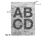
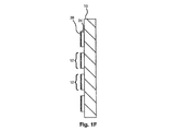
図1D、1E、および1Fは、EP 0 880 439号による視覚制御パネルを示しており、半透明であって一般的には白色であるベース層24と、一般的には4色または6色プロセスの半透明な意匠層26とを有している。図1Dにおいて、意匠層26をパネルの一方の面から視認することができ、意匠層26の反転像または鏡像を、パネルの他方の面から視認することができる。パネルの前記一方の面の観察者に有利であるよう、パネルの他方の面から意匠を照明することができる。各側の観察者は、一般的には、図1Bの一方向の視認パネルの他方の面からに比べれば明瞭度は劣るが、各側から或る程度までパネルを透視することができる。図1Fの断面は、印刷パターン12の1つ以上の白色ベース層24および意匠層26を示している。
1D, 1E, and 1F show a visual control panel according to
図2は、UVインクジェットプリンタの概略図であり、基材(光を通す材料10)が真空吸引によって真空ベッド(図示されていない)へと保持されるフラットベッド機であり、あるいは「ビーム」または「ガイド」30に沿って移動する印刷ヘッドアレイ40の下方で、基材が摩擦または他の方法によって送られる。すべてのインクジェットプリンタは、インクジェット印刷ヘッドを基材に対して移動させる手段を有しており、一般的には、印刷ヘッドが、印刷ヘッドアレイまたは印刷ヘッドアセンブリにて、シート状の基材ウェブ(ロールからロールへ)の幅を横切って横断方向または「X」方向の「ビーム」または「ガイド」に沿って移動し、ビームが、ウェブまたはシート状の基材の長さに沿って印刷対象の基材に対して長手の「Y」方向に移動する。以下のインクジェットプリンタの運動機構を、本明細書で述べる。
FIG. 2 is a schematic diagram of a UV inkjet printer, which is a flatbed machine in which a substrate (light transmissive material 10) is held by vacuum suction to a vacuum bed (not shown), or “beam” or Below the
運動機構1:印刷ヘッドが、固定の印刷ヘッドビームに沿ってX方向に段階的に移動するが、初期移動は、Y方向に高速で往復運動する真空ベッド(基材を保持している)による。 Movement mechanism 1: The print head moves stepwise in the X direction along a fixed print head beam, but the initial movement is by a vacuum bed (holding the substrate) that reciprocates at high speed in the Y direction. .
運動機構2:印刷ヘッドが、最初にX方向にビームを横切って(高速)移動し、真空ベッド(基材を保持している)が、Y方向に段階的に移動する。 Movement mechanism 2: The print head first moves across the beam in the X direction (high speed), and the vacuum bed (holding the substrate) moves stepwise in the Y direction.
運動機構3:印刷ヘッドが、最初にX方向にビームを横切って(高速)移動し、ビームが、基材を保持している固定の真空ベッドの上方をY方向に段階的に移動する。 Movement mechanism 3: The print head first moves across the beam in the X direction (high speed), and the beam moves stepwise in the Y direction over a fixed vacuum bed holding the substrate.
運動機構4:印刷ヘッドが、X方向に固定のビームを横切って主として(高速)移動し、基材(ロールからロール、またはシート)が、例えば摩擦による送りによってY方向に段階的に移動する。 Movement mechanism 4: The print head moves mainly (high speed) across the beam fixed in the X direction, and the substrate (roll to roll or sheet) moves stepwise in the Y direction, for example, by frictional feed.
本明細書においては、X方向の印刷ヘッドの最初の動きまたは最初のパスを、r‐l(右から左)と称し、戻りの動きをl‐r(左から右)または戻りパスと称する。 In this specification, the first movement or first pass of the print head in the X direction is referred to as rl (right to left) and the return movement is referred to as rr (left to right) or return path.
個々の印刷機は、組み合わせの機構を有することができ、例えばLeggett and Plattによって製造されているUVインクジェット機は、運動機構3および4を可能にしている。
Individual printing presses can have a combination of mechanisms, for example a UV inkjet machine manufactured by Leggett and Platt allows for a moving
摩擦送りは、基材の滑りおよび傾きを招く可能性があり、一連のインクの層の位置合わせを欠くことにつながる。インク塗布の間の機械的な動きはすべて、機械的な公差を生じ、或る程度の位置合わせの欠如につながる。 Frictional feed can lead to slip and tilt of the substrate, leading to a lack of alignment of a series of ink layers. Any mechanical movement during ink application creates mechanical tolerances, leading to some lack of alignment.
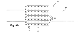
図3AおよびBが、印刷ヘッド50を備える概念的な印刷ヘッドアレイ40を示しており、印刷ヘッド50のそれぞれが、単列のインクジェットノズル52を有しており、1つの印刷ヘッドのすべてのノズルが、インクリザーバへと接続されており、印刷ヘッドは、概念上、印刷B、S、W、W、C、M、Y、Kの順に配置されている。図3Aでは、印刷ヘッドアセンブリが、運動機構2〜4に適するように向けられている一方で、図3Bでは、印刷ヘッドアセンブリが、運動機構1に適するように向けられている。しかしながら、任意の位置に追加の白色を備えている従来からのCMYK印刷ヘッドアレイを、別個の層が別個にソフトウェアによって駆動されるため、後述の印刷手順1〜3において使用可能である。
FIGS. 3A and B show a
本発明の方法は、X‐Yの運動および所望の層の印刷の種々の手順にて実行可能である。以下の印刷手順のいずれにおいても、UVインクジェット印刷が、任意選択により、インクジェットの付着の所望の分布および厚さを達成するために、個々のノズルの複数発射および/またはノズルの間隔中心またはピッチの間での横振動を含んでいる。すべての印刷手順1〜6が、印刷機から光透過性を取り除くことなく、各印刷手順の各段階の間に実質的に遅延なく、1つの印刷作業において行われる。 The method of the present invention can be carried out in various procedures for XY motion and printing of the desired layer. In any of the following printing procedures, UV inkjet printing is optionally performed with multiple firings of individual nozzles and / or nozzle spacing centers or pitches to achieve the desired distribution and thickness of inkjet deposition. Includes lateral vibration between. All printing procedures 1-6 are performed in one printing operation without removing light transparency from the printing press and with substantially no delay between each step of each printing procedure.
印刷手順1〜6は、ベース層および意匠カラー層の印刷の順序において変化する。印刷手順4〜6は、一般的には、標準的なインクジェットプリンタの印刷ヘッドの構成の補正、および/またはインクジェットノズルの新規な発射順序、および/または特別なソフトウェアを、そのような機械の従来からの使用と比べて必要とする。 The printing procedures 1 to 6 change in the printing order of the base layer and the design color layer. The printing procedures 4-6 generally involve correction of the printhead configuration of standard inkjet printers, and / or new firing sequences of inkjet nozzles, and / or special software, such as conventional machines. Necessary compared with use from.
デジタル式で印刷されるインクの単一の塗布は、一般的には、
(i)個々のノズルからの単一の付着または滴下、あるいは
(ii)一般的には単一色のインクの単一の印刷ヘッドまたは印刷ヘッドの積層アレイ内の複数のノズルの同時発射
の印刷を意味する。
A single application of digitally printed ink is generally
(I) a single deposit or drop from an individual nozzle, or (ii) a simultaneous print of multiple nozzles in a single print head or a stacked array of print heads, typically a single color ink. means.
ベース層の印刷において、インクの単一の塗布が、好ましくは、基材または先のインク層を少なくとも1つの層、一般的には2つ以上の層によって覆う重なり合う付着をもたし、個々のインクジェットノズルが、所望の1つ以上の領域のすべてを覆うために重なり合いを付着させる。異なる層が、任意選択により、複数回のパスまたは1回のパスによって塗布される。インクが、光透過性材料に対する印刷ヘッドアセンブリの初期移動の一方向においてノズルから排出され(いわゆる、単方向または単一の塗布)、初期移動の両方向においてノズルから排出される(いわゆる、双方向の塗布)。インクの付着の形状は、ノズルから基材までの飛行距離、衝突の角度、衝突の速度、およびインクの粘度などといった多数の要因によって決まり、CMYKまたはKYMCの順序の固定された印刷ヘッドアレイによる双方向の塗布において欠陥につながる可能性がある。必要な一様性を備える必要な厚さのベース層の印刷を、個々の印刷ヘッドにおいてインクジェットノズルの連続線をずらすことによって補助することができる。あるいは、それぞれが単一のノズル線を備えている連続する印刷ヘッドを、ずらされた幾何学的関係に重ねることができる、CMYKの意匠層において、塗布の順序(例えば、C、M、T、次いでK)が、得られる視覚効果にとって重要である。 In printing a base layer, a single application of ink preferably has an overlapping attachment that covers the substrate or the previous ink layer with at least one layer, typically two or more layers, and individual An inkjet nozzle applies an overlap to cover all of the desired region or regions. Different layers are optionally applied by multiple passes or a single pass. Ink is ejected from the nozzle in one direction of the initial movement of the printhead assembly relative to the light transmissive material (so-called unidirectional or single application) and from the nozzle in both directions of the initial movement (so-called bi-directional) Application). The shape of the ink deposit is determined by a number of factors such as the flight distance from the nozzle to the substrate, the angle of impact, the speed of impact, the viscosity of the ink, etc., both with a fixed printhead array in CMYK or KYMC order Can lead to defects in directional coatings. Printing the required thickness of the base layer with the required uniformity can be aided by shifting the continuous lines of inkjet nozzles in the individual print heads. Alternatively, in a CMYK design layer where successive printheads, each with a single nozzle line, can be superimposed in a shifted geometric relationship, the order of application (eg, C, M, T, K) is then important for the visual effect obtained.
双方向の塗布は、一般的には、各方向における必要な色の印刷の異なる順序を可能にするために、特別な印刷ヘッド構造および/または発射順序を必要とする。 Bi-directional application generally requires a special printhead structure and / or firing order to allow a different order of printing the required color in each direction.
印刷手順1においては、ベース層が、その1つ以上の領域の全体を覆って1段階で印刷される。これは、残りの1つ以上の層を順次印刷する前に、パネルのうちのベース層によって覆われる領域、一般的には印刷パターンの全領域の上方で、XおよびYの両方向の機械的移動を必要とする。ソフトウェアが、最初に、印刷パターン全体を光透過性材料へと一層で印刷するよう、黒色インクのノズルに指示する。黒色層は、1回のパスまたは複数回のパスで塗布される実質的に不透明な黒色層Bまたは半透明なプロセス黒色層Kであり、かつ/あるいはCMYKの組み合わせによる暗い光吸収層である。次いで、任意選択により、ソフトウェアが、黒色層の直上へと印刷パターン全体を一層で印刷するよう、銀色インクのノズルに指示する。図4が、光透過性材料10の平面図を示しており、印刷パターン12の全領域に黒色のベース層20が印刷され、銀色のベース層22が途中まで印刷されている。一般的には、次いで、ソフトウェアが、印刷パターン全体を1つ以上の白色層で印刷して、CMYKの意匠に対する背景として適切な白色の厚さ、色調、明度、および彩度を実現するよう、白色インクのノズルに指示する。次いで、CMYK意匠層が、印刷パターンの領域の全体にわたって白色のベース層の上へと印刷される。この印刷手順1は、パネル領域全体にわたって印刷ヘッドを順次、機械的に移動させなければならなおという欠点を有しており、一般的には、一連のインク層同士の位置合わせを或る程度欠くことになり、ロールからロールへと巻き取られる基材ウェブの方向について逆方向の移動を提供していないUVデジタルインクジェット機では不可能である。
In the printing procedure 1, the base layer is printed in one step covering the whole of the one or more areas. This is a mechanical movement in both the X and Y directions over the area of the panel that is covered by the base layer, typically the entire area of the printed pattern, before printing the remaining one or more layers sequentially. Need. The software first instructs the black ink nozzles to print the entire printed pattern in one layer onto the light transmissive material. The black layer is a substantially opaque black layer B or translucent process black layer K applied in one pass or multiple passes, and / or a dark light absorbing layer with a combination of CMYK. Then, optionally, the software instructs the silver ink nozzles to print the entire print pattern in a single layer directly above the black layer. FIG. 4 shows a plan view of the
印刷手順2は、すべてのベース層および意匠層が別個に印刷される点で印刷手順1に類似しているが、第2の印刷手順は、連続した塗布の領域を、図5に示されているように、印刷パターンの全領域のうちの或るセクションまたは部分、一般的には印刷ヘッドの初期移動の方向のパネルの広がりの全体にわたる選択された塗布幅に限定している。この第2の印刷手順の効率を最大にするために、印刷パターン12が、印刷ヘッドアセンブリ40のインクジェットノズルのアレイの幅によって包含される幅「W」で印刷される。一連の層の塗布同士の間の印刷ヘッドアセンブリ40および光透過性材料10の相対移動が、印刷ヘッドの動きという1つの軸にのみ限られ、少なくなるため、一般的には、位置合わせが、印刷手順1よりも良好になる。この方法のとくに好都合な例は、印刷ヘッドの移動の初期方向に平行に延びる線からなる印刷パターンを印刷することにある。図5において、印刷ヘッドアセンブリ40の初期の高速移動方向は、ビーム30に沿った方向Xである。したがって、それぞれの線の縁が、印刷ヘッドアセンブリ40を光透過性材料10に対して二次の方向または段階的な方向に動かすことなく印刷され、印刷手順1よりも一貫した線の縁の位置合わせが達成可能になる。この方法のさらなる改善は、一連の線グループ同士の相互境界が、二次の移動方向における印刷ヘッドアセンブリおよび光透過性材料の相対移動の後に、隣り合う2つの2つの線の間のすき間に位置する場合に達成され、印刷パターンの1つ以上の印刷領域において相互の境界に重なり合いが生じ、あるいはすき間が残るという「クロストーク」、「インターレーシング(interlacing)」、または他の問題など、相互の干渉の問題(「横縞(banding)と称されることが多い)が回避される。好ましくは、印刷ヘッドアセンブリが、印刷される複数の線の2つの最も外側の線の外縁の間の印刷幅Wに線の間のすき間を加えた距離にて、二次の移動方向に段階的に動かされ、相互の境界を有する印刷幅の印刷に比べ、印刷の時間をさらに少なくしている。このような線の縁の位置合わせを、層間の位置合わせの欠如が、初期移動の方向における運動機構の横方向の機械公差、インクジェットの整列、インク点のゲインまたは収縮、および種々の二次的原因から生じうる非一様な印刷縁を指す用語である「スパッタ」の他の原因へと大いに抑制されているため、実質的に正確な位置合わせと称することができる。
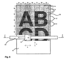
印刷手順3においては、幅Wおよび移動距離Mのマイクロ領域16を描いている図6に示されているように、印刷パターンの「マイクロ領域」が順次印刷される。「マイクロ領域」は、一般的には、印刷ヘッドアレイによって覆われる領域によって包含され、異なる層の塗布の間に必要とされる移動は、印刷ヘッドアレイ内の個々の色の間隔に限定される。印刷手順3においては、2つのマイクロ領域間の相互の境界14において、2つの隣接するマイクロ領域内の層の連続の間に、或る程度の重なりまたはすき間が存在しうる。それは、当接する隣接層の正確な位置合わせが不可能であるためであり、特定の基材上の特定のインクの点のゲインまたは収縮ゆえであり、さらには個々の印刷機の運動機構について、例えば個々のノズルの角度および間隔ならびにX‐Yの移動における機械的な公差が不可避であるためである。
In the
印刷手順1、2、および3は、各層の多重パスでの印刷を可能にし、充分なインクステーションおよびソフトウェア操作のみによって達成でき、例えばCMYKおよび1つまたは2つの白色ステーションを有する標準的なUVインクジェットプリンタを、多重のKまたはCMYK黒色ベース層、多重の白色ベース層、および後続のCMYK意匠層を印刷するようにプログラムすることができる。例えば基材によるインクの吸収や、熱および/または水分による基材の動きなどといった位置合わせの欠如の他の原因は、UVインクジェットインクにおいては大きくなく、一般的に層間にかなりのX‐Y運動および加熱/空気乾燥を必要とする水性または油性のインクに対する顕著な利点である。
印刷手順4においては、層のそれぞれが、印刷ヘッドアセンブリの単一のパスにて印刷される。各層は、この1回のパスによって達成される必要とされる基材の被覆度および視覚的な不透明性を有するように求められる。したがって、個々のカラー印刷ヘッドは、例えば黒色、銀色、白色、白色、C、M、Y、Kなど、印刷ヘッドアレイにおいて個々の層の色を印刷する必要な順序になければならない。印刷ヘッドは、一般的には、必要とされる層の被覆度および厚さを保証するために、複数パスの印刷よりもゆっくりと移動する。この印刷手順4は、あらゆる印刷パターンについてもっとも正確な層の位置合わせをもたらすが、例えば運動機構1において印刷ヘッドビームに直交する線、および運動機構2〜4において印刷ヘッドビームに平行な線など、印刷ヘッドの初期移動方向に平行な線からなる印刷パターンが、依然として好ましい。図7Aが、X方向の初期移動方向にビーム30に沿って移動する印刷ヘッドアレイ40を示しており、印刷ヘッドビーム30が光透過性材料10を横切ってY方向に段階的に移動し、あるいは光透過性材料10が固定されたビーム30の下方をY方向に段階的に移動する。印刷パターン12は、印刷ヘッドビームと平行に延びる線からなるパターンであり、図1Aに示した意匠と同様の意匠を有する意匠層26を備えている。印刷ヘッドアレイが、必要とされる順序で必要とされる色のインクジェットノズルを発射させることができるように構成されており、例えば図3Aが、印刷ヘッド50を備える概念的な印刷ヘッドアレイ40を示しており、印刷ヘッド50のそれぞれが、単列のインクジェットノズル52を有しており、1つの印刷ヘッドのすべてのノズルが、インクリザーバへと接続されており、印刷ヘッドは、概念上、印刷B、S、W、W、C、M、Y、Kの順に配置されている。図7Bが、右方から左方へと移動して一連のベース層および意匠層を印刷ヘッドアセンブリ40の1回のパスで作り上げている印刷ヘッドアレイを示しており、黒色のベース層20が、銀色のベース層22に先立って印刷され、銀色のベース層22は、2つの白色ベース層24に先立って印刷され、白色のベース層24は、個々の意匠カラー層CMYKからなる意匠層26に先立って印刷されている。任意選択により、各層のインクのUV硬化を助けるために、黒色、任意選択による銀色、および白色の印刷ヘッドは、お互いから離され、かつCMYKの印刷ヘッドから離される。しかしながら、市販の機械において現在のところ利用できる印刷ヘッドでは、1回のCMYKパスによって印刷された意匠について結果として知覚される品質が比較的粗く、知覚される色の彩度が弱くなり、あるいは低くなる。特定の意匠に適している可能性があるが、この印刷手順4においては、CMYKの色のそれぞれについてノズルの列を二重、三重、または四重にすることが好ましい。
In printing procedure 4, each of the layers is printed in a single pass of the printhead assembly. Each layer is required to have the required substrate coverage and visual opacity achieved by this one pass. Thus, the individual color printheads must be in the necessary order to print the colors of the individual layers in the printhead array, such as black, silver, white, white, C, M, Y, K, etc. The print head generally moves more slowly than multi-pass printing to ensure the required layer coverage and thickness. This printing procedure 4 provides the most accurate layer alignment for any print pattern, but for example, a line perpendicular to the print head beam in motion mechanism 1 and a line parallel to the print head beam in motion mechanisms 2-4, etc. A print pattern consisting of lines parallel to the initial movement direction of the print head is still preferred. FIG. 7A shows a
印刷手順5および6は、1つ以上のベース層および4色または6色プロセスの意匠の1回のパスでの同時印刷を可能にしつつ、例えば図8A〜Nに印刷パターンの個々の部位の断面によって示されているように、或る範囲の視覚制御パネルの製造に必要とされる層の作成を可能にする。 Printing procedures 5 and 6 allow for simultaneous printing in one pass of one or more base layers and a four-color or six-color process design, for example, cross-sections of individual portions of the print pattern in FIGS. Allows creation of the layers required for the production of a range of visual control panels.
図8A〜Fは、GB 2 165 292号による種々の種類の視覚制御パネルについて、層の印刷の順序の例を示している。図8AおよびBは、透明なフィルム10(例えば、粘着ポリエステルフィルム)を含んでおり、窓の外側へと貼り付けられる一方向の視認パネルを表わしている。図8Aにおいて、プロセス黒色(K)ベース層64に、1つ以上の白色ベース層24が、間に任意選択による銀色ベース層を備えつつ続いており、さらにシアン61(C)、マゼンタ62(M)、イエロー63(Y)、およびプロセス黒色64(K)の意匠プロセスカラー層を有する意匠層26が続いている。図8Bは、スポットカラー不透明黒色層20(B)、銀色層22(S)、2つの白色層24(W)、および図8Aと同様の意匠層26を示している。
8A-F show examples of layer printing order for different types of visual control panels according to
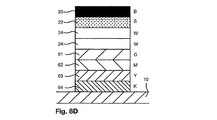
図8CおよびDは、例えばフィルムを含んでおり、窓の内側へと貼り付けられる一方向の視認パネルを表わしている。図8Cにおいては、意匠層26が、鏡像または逆さ読み取りの意匠であって、やはり逆順KYMCで印刷される意匠カラー層を有している。窓の内側へと貼り付けられた後で、この意匠は、窓の外側の観察者にとって正しい読み取りとして視認できる。意匠層26に、白色およびプロセス黒色の層24および64が続いている。図8Dは、同様の製品を示しているが、窓からの視認を改善する不透明な黒色層20(B)を備えている。黒色層が、より黒く、より視覚的に不透明であり、より光を反射させないほど、建物または車両の窓の内側の観察者が、より良好に窓越しに見ることができる。
FIGS. 8C and D represent a unidirectional viewing panel that includes, for example, a film and is applied to the inside of the window. In FIG. 8C, the
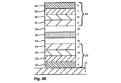
図8Eは、GB 2 165 292号によるパネルを表わしており、逆さ読み取りで透明な材料へと印刷され、透明な材料を通して視認することができる1つの意匠層26と、白色、銀色、次いで白色のベース層24、22、および24とを有しており、さらに他方の側から視認可能である正しい読み取りの意匠層26が後続している。
FIG. 8E represents a panel according to
図8Fは、意匠層26を光透過性材料10の各側に印刷して備えるパネルを示している。
FIG. 8F shows a panel provided with the
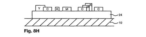
図8Gは、EP 0 880 439号によるパネルを表わしており、白色ベース層24を備えているが、黒色または銀色のベース層は備えていない。図8Gと同じ製品が、白色ベース層24の一部分へのシアン(C)、マゼンタ(M)。イエロー(Y)、およびプロセス黒色(K)のカラーUVインクの付着によって、図8Hに異なるやり方で表わされている。
FIG. 8G represents a panel according to
図8Iにおいては、意匠層のプロセスカラーCMYKの個々の付着の間のすき間が、白色の充填層70によって埋められており、この充填層70は、意匠の白色の領域に視覚的により明るい白色を生み出すという効果を有しており、あるいはCMYKの付着と組み合わせて眺められることで、意匠色の視覚的に必要とされる知覚範囲および階調を生み出すためのものである。
In FIG. 8I, the gaps between the individual depositions of the process layer CMYK of the design layer are filled with a
意匠層が白色で充填されているか否かにかかわらず、図8Jは、ベース層(例えば、白色ベース層24)が、例えば特定の意匠効果の達成または全体としてのパネルの半透明性の向上のために、ベース層内に規則的または不規則な空隙またはすき間25のパターンを任意選択により有する旨を示している。
Regardless of whether the design layer is filled with white or not, FIG. 8J shows that the base layer (eg, white base layer 24) is capable of achieving a particular design effect or improving the overall translucency of the panel, for example. Therefore, it is shown that the base layer optionally has a pattern of regular or irregular voids or
図8Kは、CMYKのプロセスカラーからなる半透明な多色プロセス意匠層の背景として透明または半透明な基材10および白色のベース層24を有しているパネルにおいて、暗い領域の演出を改善する新規な手段を概略的に表わしている。このようなパネル(透視グラフィックパネルなど)においては、プロセス黒色Kが半透明であり、白色の背景に対して眺めたときに、黒色と言うよりはむしろ暗い灰色として知覚される。黒さを改善するために、黒色であり、または他の形できわめて暗くなくてはならない領域へと、CMYの付着が塗布されることが多い。好都合には、白色ベース層を備える透明な基材において、図8Kに示されているようにプロセス黒色Kの付着に一致させて白色ベース層24に空隙またはすき間25を残すことによって、プロセス黒色が自然に付着させられるあらゆる領域の下方から、白色ベース層が取り除かれている。図8Lは、同じパネルを示しているが、プロセス黒色Kが、白色ベース層24に空隙が存在する場所において光透過性材料10へと付着させられている。
FIG. 8K improves the rendering of dark areas in a panel having a transparent or
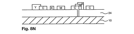
反対に、暗色の所望のデジタル表現が、例えばプロセス黒色、ならびにシアン、マゼンタ、およびイエローの重ね合わせの層を必要とするRIPをもたらす場合、「下色除去」という公知の方法が、例えばインク層の効果を助け、さらにはインクのコストを少なくするため、インクの重ね合わせ層の数を少なくするためにしばしば使用される。図8Mは、下色除去の条件が満足される場所、例えば少なくとも層C、M、およびKの付着が重ね合わせられる場所のみの白色ベース層の空隙25を示しており、図8Mのすき間または空隙25を光透過性材料10へと付着させたインクで満たして示している図8Nに、より写実的に示されている。
Conversely, if the desired digital representation of the dark color results in a RIP that requires, for example, a process black, and an overlay layer of cyan, magenta, and yellow, a known method of “undercolor removal” is, for example, an ink layer It is often used to reduce the number of ink overlay layers to help reduce the cost of the ink and further reduce the cost of the ink. FIG. 8M shows the white base layer voids 25 only where the undercolor removal conditions are satisfied, for example, where the deposition of at least layers C, M, and K is superimposed, and the gaps or voids of FIG. This is illustrated more realistically in FIG. 8N, where 25 is shown filled with ink deposited on the
実施においては、ノズルおよび印刷ヘッドアレイが、製品の特定の範囲を、単方向または双方向のどちらのやり方で印刷すべきであるかを考慮して、所望の品質、効率、およびコストまで印刷するように構成される。実施例が、図9A〜Hに示されている。 In practice, nozzles and printhead arrays print a specific range of products to the desired quality, efficiency, and cost, considering whether to print in a unidirectional or bidirectional manner Configured as follows. An example is shown in FIGS.
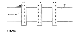
図9Aは、ビームまたはガイド30上の密に束ねられた印刷ヘッドアレイ40を示しており、それぞれの印刷ヘッド50が、例えば、それぞれがアドレス可能な64のチャネルを備えている電気的に独立な2つの圧電スライスを合計128個のジェットをもたらすように組み合わせて有しているSpectraSE‐128という印刷ヘッド(Spectra, Inc.、米国)に設けられているように、単列のノズル52を有している。ノズルは、0.020’’のノズル間間隔で一列に配置され、ノズル列の長さは64.5mm(2.54インチ)であり、例えばWWCMYK、CMYLWW、またはWCMYKWと配置された2つの白色ステーションおよびCMYKのための6つの印刷ヘッドが、現実的には、本発明の実施に望まれる印刷ヘッドの最小数である。図9Bに示されているように、プロセス黒色Kの代わりに、不透明な黒色Bの印刷ヘッドを使用することが可能である。好ましくは、例えば図9Cに示されているように、ライトシアン(CL)およびライトマゼンタ(ML)という追加の6色のプロセスカラーを有し、あるいは図9Dに示されているように、追加の不透明黒色Bおよび白色Wのステーションを有している8つの印刷ヘッド色からなるアレイが利用可能である。
FIG. 9A shows a tightly bundled
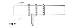
あるいは、インクジェット印刷ヘッドが、例えば86mmの印刷ヘッド幅を横切って382個のノズルからなる2つの列(合計764個のノズル)を有しているXaarOmnidot 760という印刷ヘッド(Xaar Plc、英国)に設けられているように、2列のノズルを有している。2列の印刷ヘッドは、例えば図9Eに示されているように、別個の色の供給を受け、基本的なWCMYKWのアレイをもたらすことができ、あるいは図9Fに示されているように、1つの色の供給を受けることができる。図9Gおよび9Hは、4つの2列型印刷ヘッドを備えてWCMYKCLMLWおよびBWWCMYKWという選択肢をもたらしている任意選択による構成を示している。印刷手順6においては、図9Iに示されているように、黒色および白色のベース層の印刷を目的とする不透明な黒色Bおよび白色Wのステーションを備える印刷ヘッドが、主として意匠層の印刷を目的とする他の3つの印刷ヘッドからずらされ、他の3つの印刷ヘッドを先導している。それぞれの手順において、それぞれのノズル列が、ただ1色のUV硬化型インクへと接続されて、ただ1色のUV硬化型インクを印刷する。印刷手順1のみが、基材の巻き取り能力を有するインクジェット印刷機を必要とする。 Alternatively, an inkjet printhead is installed in a print head called Xaar Omnidot 760 (Xaar Plc, UK) with two rows of 382 nozzles across a printhead width of, for example, 86 mm (total of 764 nozzles) As shown, it has two rows of nozzles. Two rows of printheads can be supplied with separate colors, for example as shown in FIG. 9E, resulting in an array of basic WCMYKWs, or as shown in FIG. Can be supplied in two colors. FIGS. 9G and 9H show an optional configuration that includes four two-row printheads and provides the options WCMYKCLMLW and BWWCMYKW. In printing procedure 6, as shown in FIG. 9I, a print head having opaque black B and white W stations for printing black and white base layers is mainly used for printing design layers. Are displaced from the other three print heads and lead the other three print heads. In each procedure, each nozzle row is connected to only one color of UV curable ink to print only one color of UV curable ink. Only printing procedure 1 requires an ink jet printer with substrate winding capability.
図9Eに示したようなWCMYKW、または図9Gおよび図10Aに示したようなWCMYKCLMLWの直列インクジェットアレイを有することは知られている。これらの構成は、による白色ベース層を有しており、さらに意匠層のうちのCMYKの付着のないあらゆる位置に任意選択による白色滴の付着の充填を有している図8G〜Nによる透視グラフィック製品の印刷に適している。一般的には、第1の白色インクジェットが、単一の白色ベース層を付着させ、CMYKの意匠層および白色の充填が後続する。より半透明度が低く、より不透明な白色ベース層が求められる場合には、2つの白色層がl‐rのパスにて付着させられ、次いで任意選択による追加の白色ベース層が続き、CMYKの意匠および任意選択による白色の充填がr‐lパスにて後続する。 It is known to have a serial inkjet array of WCMYKW as shown in FIG. 9E, or WCMYKCLMLW as shown in FIGS. 9G and 10A. These configurations have a white base layer according to FIGS. 8G-N, with the optional filling of white drop deposits at any position of the design layer without CMYK deposits. Suitable for product printing. In general, a first white ink jet deposits a single white base layer followed by a CMYK design layer and a white fill. If a less translucent and more opaque white base layer is desired, the two white layers are deposited in an lr pass, followed by an optional additional white base layer, followed by a CMYK design And optionally followed by a white fill in the rl pass.
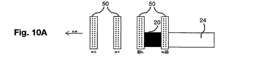
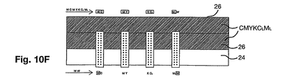
GB 2 165 292号による一方向の透視グラフィックパネルを印刷するために、一方の面からの良好な透視をもたらすために、一般的には黒色である暗い層を有する必要がり、色を設計するために明るい白色の背景を有する必要がある。これを達成するためには、通常は、複数の白色層を任意選択による中間銀色層とともに有する必要がある。印刷手順5によれば、図10Aに示されているように、WCMYKWまたはWCMYKCLMLWの直列インクジェットアレイにおいて、ノズル列の先頭または前方のセクション、チャネル、ストリーム、またはスライスを使用して黒色および白色のベース層を印刷し、残りの後続のノズルをCMYK意匠層の印刷に使用することが、すべて連続的な経過にて可能である。デジタルインクジェット印刷による意匠について一般的に受け入れ可能な標準を達成するために、必要とされる知覚分解能に応じて、CMYKインクジェットヘッドがそれぞれの意匠領域の上方を複数回(一般的には、4〜6回の間である)パスする必要がある。印刷ヘッドのノズルの長さのうちの前方の半分または4分の1が、黒色および白色ベース層の付着のために専用とされる場合、幅のうちの残りの半分または4分の3を、CMYKに専用とすることができる。図10A〜Fが、インクジェットノズルの前方の半分がベース層の印刷のために専用とされ、後方の半分が意匠層の印刷に専用とされている印刷手順5Aを示している。図10Aにおいて、プロセス黒色Kおよび右側の白色のノズル列が、最初のr‐lのパスにおいて黒色ベース層20および白色ベース層24を印刷している。図10Bの戻りのl‐rのパスにおいて、白色インクを有している両方のノズル列の前方の半分が、さらに2つの白色ベース層24を塗布する。次いで、印刷ヘッドが、図10Cの位置へと、インクジェットノズル列の幅の半分の増分にて第2の方向に移動し、したがってノズルの後方半分が、印刷済みのプロセス黒色ベース層20および3つの白色ベース層24の幅の上方に位置する。図10Cのr‐lのパスにおいて、ノズルの前方半分が、図10Aのようにベース層20および24の印刷を繰り返す一方で、後方半分は、さらなる白色層24および後続のCMYKCLML意匠層26を印刷している。CMYKCLML意匠カラー層のさらなる意匠層が、図10Dのl‐rのパスにおいて付着させられ、このとき同時に、前方半分においては、図10Bと同様のやり方で追加の2つの白色ベース層24が付着させられている。この手順が、図10EおよびFに示されているように進行し、全体として二重のCMYKCLML意匠層26がもたらされる。図10GおよびHは、印刷ヘッドおよび印刷ヘッドの初期移動方向の線からなる印刷パターンである光透過性材料10の周囲の部分画像を、より大きな縮尺で示している。しかしながら、線を、直交方向または他の任意の方向に印刷することもでき、あるいは異なる印刷パターン(例えば、点からなる印刷パターン、または光透過性材料の不連続領域を残している印刷パターン)を、この印刷手順5Aまたは他の任意の印刷手順によって、任意選択により生成することも可能である。
In order to print a one-way perspective graphic panel according to
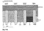
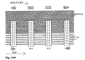
図11A〜Fの印刷手順5Bにおいては、C、M、およびYの層がプロセス黒色Kと組み合わせて使用され、より不透明であって、一般的にはGB2 165 292号による一方向の視認パネルにとって好ましい「複合黒色」ベース層20をもたらしている。図11A〜Hは別の形で図10A〜Hに類似している。
In printing procedure 5B of FIGS. 11A-F, the C, M, and Y layers are used in combination with process black K and are more opaque and generally for unidirectional viewing panels according to GB2 165 292 A preferred “composite black”
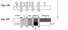
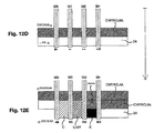
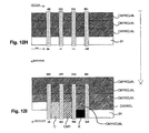
ノズルの前方4分の1がベース層の印刷に専用であって、印刷ヘッドが、それぞれの双方向のパスの後にノズル列の幅の4分の1だけ前進する場合、図12A〜Iに示されているように意匠のそれぞれの部分に6つのCMYKCLMLの印刷を付着させることができ、これが印刷手順5Cである。図12A〜Dの層の付着は、印刷幅のチャネル、ストリーム、またはスライスが、ノズル列の幅の半分ではなく、ノズル列の全幅の4分の1である点を除き、図11A〜Dの層の付着と同一である。図12E〜Iは、6つの意匠層の印刷をもたらす印刷の経過を示している。 If the front quarter of the nozzle is dedicated to printing the base layer and the print head advances by a quarter of the width of the nozzle row after each bi-directional pass, it is shown in FIGS. As shown, six CMYKCLML prints can be attached to each part of the design, which is printing procedure 5C. The deposition of the layers of FIGS. 12A-D is similar to that of FIGS. 11A-D, except that the print width channel, stream, or slice is a quarter of the full width of the nozzle row, not half the width of the nozzle row. Same as layer deposition. 12E-I show the course of printing resulting in the printing of six design layers.
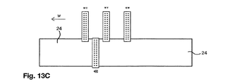
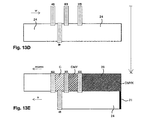
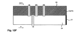
印刷手順6においては、図13A〜Iに示されているように、ベース層を印刷する1つ以上の印刷ヘッドが、主としてCMYK意匠カラー層を印刷する目的の印刷ヘッドから前方にずらされている。例えば、印刷ヘッドにおいて黒色Bおよび白色Wのインクノズル列が、通常のCMYKまたはWCMYKWの印刷ヘッドアレイの直列アレイの前方へとずらされている。図3Aにおいて、不透明な黒色ベース層21および白色ベース層24が最初のr‐lのパスにて印刷され、次いで図13Bに示されているように、l‐rのパスにて1つの白色ベース層24が後続する。さらなる2つの白色ベース層24が、図13Cのr‐lのパスおよび図13Dのl‐rのパスにて追加される。次いで、印刷ヘッドビームが、ノズル列の幅だけ段階的に動かされ、図13Eに示されているように、1つの印刷ヘッドの幅の黒色ベース層および4つの白色ベース層が、後続の印刷ヘッドの幅のさらなる白色ベース層24および意匠層の色CMYKによって印刷される。この印刷手順が図13F〜Iに示されているように続けられ、1つの黒色ベース層21、5つの白色ベース層24、および4つのCMYK意匠層26からなる一連の印刷がもたらされる。より彩度の高い、明白に高分解能な意匠が求められる場合には、ずらされている印刷ヘッドからの白色および直列な印刷ヘッドからのCMYKについてさらなるパスが実行され、例えば6×、8×、あるいはそれ以上のCMYKパスが達成される。あるいは、例えば黒色の単一の印刷ヘッドを、二重のCMYK印刷ヘッドおよび二重の白色充填用印刷ヘッド(図9Fに示されているような)の前方へとずらされている白色の2つの印刷ヘッドの前方へとずらすことができる。
In print procedure 6, as shown in FIGS. 13A-I, one or more print heads that print the base layer are shifted forward from the print head intended primarily for printing the CMYK design color layer. . For example, the black B and white W ink nozzle rows in the print head are shifted to the front of a series array of normal CMYK or WCMYKW print head arrays. In FIG. 3A, an opaque
黒色および白色であるベース層の色、ならびに例えばシアン、マゼンタ、イエロー、およびプロセス黒色(すなわち、CMYK)である意匠層の色が、印刷アセンブリの一回のパスにおいて同時に印刷されるならば、本発明の方法にとって好都合である。 If the color of the base layer, which is black and white, and the color of the design layer, for example cyan, magenta, yellow, and process black (ie CMYK), are printed simultaneously in one pass of the printing assembly, the book Convenient for the inventive method.
発射の順序または一連の色インパルスの順序は、特定の種類の視覚制御製品に合わせたソフトウェア・プログラムまたはルーチンによって決定される。 The order of firing or sequence of color impulses is determined by a software program or routine tailored to a particular type of visual control product.
印刷手順1、したがって印刷手順1〜6のすべての可能性が、Mimaki UJF‐605CというデジタルUVインクジェットプリンタおよびMimakiインクを使用し、無色透明のポリエステルフィルム基材へとテスト印刷を行うことで確認されている。テスト印刷においては、最初に不連続な反転印刷のKYMC意匠を有し、次いで白色の2つの層を有し、続いて黒色のK層を有している矩形要素のアレイであって、間に透明なすき間を有している矩形要素のアレイを印刷することによって、
(i)光透過性の材料、
(ii)3つのベース層(黒色および2つの白色)を有するUVインクジェット印刷、および
(iii)CMYK意匠のUVインクジェット印刷
など、透視グラフィックパネルに必要とされる印刷の特徴のすべてが確認されている。テストは、1つの印刷作業において行われた。
All possibilities of printing procedure 1, and therefore printing procedures 1-6, were confirmed by performing a test print on a colorless transparent polyester film substrate using a Mimaki UJF-605C digital UV inkjet printer and Mimaki ink. ing. In test printing, an array of rectangular elements having first a discontinuous reversal KYMC design, then two white layers, followed by a black K layer, By printing an array of rectangular elements with transparent gaps,
(I) a light transmissive material;
All of the printing features required for fluoroscopic graphic panels have been identified, including (ii) UV inkjet printing with three base layers (black and two white) and (iii) UV inkjet printing of CMYK designs . The test was performed in one printing operation.
インクジェットノズル、ヘッド、またはインクリザーバへの接続について、特別な構成変更は不要であり、単に、プロセス黒色、白色、およびCMYKカラー層を必要とされる順序で生成するため、コンピュータの標準のソフトウェアへとデータを入力するだけでよかった。このテスト製造において、プロセス黒色Kおよび白色の層は、意匠の印刷のために適切な不透明度および白さを有しており、意匠は、パネルの他方の面からは視認不可能であった。 No special configuration changes are required for connection to inkjet nozzles, heads, or ink reservoirs, just to generate standard process black, white, and CMYK color layers in the required order, to standard computer software It was only necessary to input data. In this test production, the process black K and white layers had opacity and whiteness suitable for printing the design, and the design was not visible from the other side of the panel.
印刷手順1〜4および6は、特別なソフトウェアまたは印刷機「ファームウェア」(プリンタのコンピュータのためのソフトウェア)を必要としない。しかしながら、印刷手順5は、ノズルの前方のベース層用チャネルをベース層の印刷のために分離して管理し、残りの後方のチャネルを意匠層の印刷に限定するため、コンピュータ「ファームウェア」ロジックのプログラム変更を必要とする。 Printing procedures 1-4 and 6 do not require special software or printing press "firmware" (software for the printer computer). However, printing procedure 5 separates and manages the base layer channel in front of the nozzles for base layer printing, and limits the remaining back channels to design layer printing, so Requires program change.
本発明の方法の上述の印刷手順のいずれにおいても、例えば一般的な割合よりも高い白色顔料(伝統的には、二酸化チタン)の割合、および任意選択によるより微細な白色顔料粒子分布範囲(例えば、1ミクロン未満の粒子サイズ)など、白色インクの不透明度を改善するためにさらなる手段をとることができる。白色インクについては、他の色と比べて特別な送出システムが必要とされる。白色インクの一貫した不透明度を、印刷プロセスの全体にわたる白色インクリザーバの連続攪拌、および最適な白色インクリザーバ温度の維持、および/または印刷ヘッドの温度制御によって、不透明な白色を達成するための最適なインクの流動学を維持することによって促進することができる。本明細書においては、用語「不透明な白色」は、CMYKインクジェットインクを所望の知覚色をもたらすように印刷するための適切な背景をもたらすための充分な「彩度」、「明度」、および厚さの白色インクを意味する。UVインクジェットインクは、一般的には、オリゴマー、モノマー、光重合開始剤、顔料、および添加剤を含んでいる。本発明の方法による印刷においては、少なくともベース層の白色インクおよび任意選択による銀色インクにおいて、比較的高い温度で塗布された場合に効率よく硬化してより高い彩度のより「不透明」なインク層を形成するインクを得るべく残りの構成成分の割合を高めるために、添加剤を少なくすることが好ましい。さらには、インクを硬化させるためにスクリーン印刷においてより一般的に使用されているUV‐Aランプを使用することが好都合である。また、インクの付着を改善するために、一般的には視覚制御パネルの製造に使用される透明基材(例えば、印刷処理されたポリエステル、PVC、アクリル、およびポリカーボネート)であるが、特定の光透過性材料の表面エネルギーに適するようにインクを採用することが好都合である。また、フィルム状の光透過性材料においては、柔軟なUV硬化型インクを使用することも重要である。 In any of the above-described printing procedures of the method of the present invention, for example, the proportion of white pigment (traditionally titanium dioxide) higher than the common proportion, and optionally a finer white pigment particle distribution range (e.g. Further measures can be taken to improve the opacity of the white ink, such as a particle size of less than 1 micron. For white ink, a special delivery system is required compared to other colors. Optimal to achieve an opaque whiteness by consistent white ink opacity, continuous stirring of the white ink reservoir throughout the printing process, and maintaining an optimal white ink reservoir temperature and / or temperature control of the print head Can be facilitated by maintaining the ink rheology. As used herein, the term “opaque white” refers to sufficient “saturation”, “lightness”, and thickness to provide a suitable background for printing a CMYK inkjet ink to provide the desired perceived color. Means white ink. UV inkjet inks generally include oligomers, monomers, photoinitiators, pigments, and additives. In printing according to the method of the present invention, at least in the base layer white ink and optionally the silver ink, when cured at a relatively high temperature, the ink layer cures more efficiently and is a more "opaque" ink layer with higher saturation In order to increase the proportion of the remaining constituent components in order to obtain an ink for forming the ink, it is preferable to reduce the additive. Furthermore, it is advantageous to use UV-A lamps that are more commonly used in screen printing to cure the ink. It is also a transparent substrate (eg, printed polyester, PVC, acrylic, and polycarbonate) that is typically used in the manufacture of visual control panels to improve ink adhesion, but with specific light It is advantageous to employ the ink so as to suit the surface energy of the permeable material. It is also important to use a flexible UV curable ink in a film-like light-transmitting material.
ドロップ・オン・デマンド(DOD)の印刷ヘッドの設計上の考慮事項として、
(i)分解能およびノズル・ピッチ、
(ii)液滴排出周波数、
(iii)クロストーク、
(iv)寿命、
(v)注入/気泡除去、
(vi)液滴配置精度、
(vii)レイテンシ、および
(ix)温度制御
が挙げられる。
Design considerations for drop-on-demand (DOD) printheads include:
(I) resolution and nozzle pitch,
(Ii) droplet discharge frequency,
(Iii) crosstalk,
(Iv) lifetime,
(V) injection / bubble removal,
(Vi) Droplet placement accuracy,
(Vii) Latency, and (ix) Temperature control.
液滴の配置または液滴の投下の精度は、
(i)ジェット対ジェットの製造公差、
(ii)時間のばらつきを持つ単一のジェット、
(iii)ノズルの直線度、
(iv)ノズルおよび表面の濡れ、
(v)ノズルプレートの汚染、
(vi)インクの構成および状態、
(vii)液滴の速度、および
(viii)液滴の飛行経路および投てき距離
における機械の公差に依存して決まる。
The accuracy of drop placement or drop drop is
(I) Jet-to-jet manufacturing tolerances,
(Ii) a single jet with time variations,
(Iii) Nozzle linearity,
(Iv) nozzle and surface wetting,
(V) Nozzle plate contamination,
(Vi) configuration and state of ink;
Depends on (vii) droplet velocity and (viii) mechanical tolerances in droplet flight path and throw distance.
これらの変数および要因を、インクジェット印刷視覚制御パネルの特定の要件に合わせて「チューニング」することができる。印刷ヘッドの配置形状は、アーキテクチャと称されることもあるが、プリンタの種類および対象とする市場に依存して決まる。例えば、大型フォーマットの屋外広告においては高い分解能を有する必要はなく、実際に、低い分解能の間隔の大きなインクの付着が、視覚的影響のために好ましいが、そのような印刷材料を指定する者によってしばしば理解されていない点である。意匠の高い分解能の印刷は、印刷されない部分の比較的粗い性質に鑑み、視覚制御パネルにおいてはほとんど必要とされない。 These variables and factors can be “tuned” to the specific requirements of the inkjet printing visual control panel. The layout of the print head is sometimes referred to as an architecture, but depends on the type of printer and the target market. For example, large format outdoor advertisements do not need to have high resolution, and in fact, large ink deposits with low resolution intervals are preferred for visual effects, but by those who specify such printing materials. This is often not understood. High resolution printing of designs is rarely required in visual control panels in view of the relatively rough nature of the unprinted parts.
ジェットの整列ずれまたはジェットの不安定によって引き起こされる「横縞」の印刷欠陥を、「インターレーシング」、たとえばノズルの微細なウィービングによって軽減できる。しかしながら、実質的に正確に位置合わせされた印刷パターンの縁を生み出すためには、本明細書に記載のとおり、ノズルの整列が一般的に好ましい。 “Horizontal stripes” printing defects caused by jet misalignment or jet instability can be mitigated by “interlacing”, eg, fine weaving of the nozzles. However, in order to produce substantially precisely aligned printed pattern edges, nozzle alignment is generally preferred as described herein.
印刷ヘッドのノズル密度が大であるほど、印刷に必要とされるパスの数は少なくなる。 The greater the nozzle density of the print head, the fewer the number of passes required for printing.
本明細書においては、「印刷品質」とは、印刷による点が、個々または集合的な基準において、意図される点にどの程度近く類似するかを指している。印刷品質は、例えば印刷パターンの縁について知覚される位置合わせを損なう縁スパッタを監視するために、注意深く監視されなければならない。 As used herein, “print quality” refers to how close a printed point is to the intended point on an individual or collective basis. Print quality must be carefully monitored, for example, to monitor edge spatter that impairs perceived registration for the edges of the printed pattern.
本明細書においては、「像品質」とは、印刷による最終的な画像が、意図される画像にどの程度近く類似するかを指す。知覚される像品質は、他の像欠陥を隠す傾向にある非印刷部分の不連続性ゆえ、視覚制御パネルの製造においては達成がより容易であることが多い。 As used herein, “image quality” refers to how close the final image from printing is to the intended image. Perceived image quality is often easier to achieve in the manufacture of visual control panels due to non-printing discontinuities that tend to hide other image defects.
液滴の配置の精度は、主として、ジェット対ジェットの製造公差、ノズルの直線度、主としてノズルおよび表面の濡れならびにノズルプレートの汚染に依存する経時的な個々のジェット発射における問題、ならびに印刷設備のX‐Y移動の公差および投てき距離の公差に依存する。他の問題として、インクドットの縁の精度、ドットのゲインまたは収縮、および色にじみが挙げられる。印刷手順3および4はどちらも、とくには黄色の上への黒色で、色のにじみの影響を受けやすい。色のにじみは、例えばカチオン性のカーボンブラックおよびアニオン性の黄色染料など、反対に帯電した顔料を使用することによって少なくすることができる。
Droplet placement accuracy is primarily a matter of jet-to-jet manufacturing tolerances, nozzle linearity, nozzle and surface wetting and problems with individual jet firings over time dependent on nozzle plate contamination, and printing equipment. Depends on XY movement tolerance and throw distance tolerance. Other problems include ink dot edge accuracy, dot gain or shrinkage, and color bleed. Both
パネルの耐久性を、印刷パターンにおいて実質的に正確な位置合わせで透明インクまたはワニスを印刷することによって、向上させることができる。これは、あらゆる印刷層がたとえ無色透明であっても変形した(平面でない)表面を有し、したがって透視グラフィックパネルの透視品質をゆがめてしまうため、印刷パターンの領域に制限されなければならない。 The durability of the panel can be improved by printing the clear ink or varnish with substantially accurate alignment in the printed pattern. This must be limited to the area of the printed pattern because every printed layer has a deformed (non-planar) surface even if it is colorless and transparent, thus distorting the perspective quality of the perspective graphic panel.
印刷対象のあらゆる種類の光透過性材料の表面エネルギーを、適切なUVインクの選択を助けるために確立することが好ましい。 It is preferable to establish the surface energy of any type of light transmissive material to be printed to help select an appropriate UV ink.
しかしながら、インクジェット印刷ヘッドの設計は、より高品質かつより高速であるインクジェットの液滴の発射ならびに硬化後に得られる液滴の形状および付着を達成するため、今後も熱心な研究および開発の対象であり続ける。本発明による望ましい1回パスでの製造は、例えば英国のIMIEurope Ltdによって製造されているToneJet(商標)という印刷ヘッドなど、個々のインクジェットノズル列を有しておらず、代わりに連続的な溝に溝の長さに沿ったインクの選択的な発射を可能にする造作を備えている印刷ヘッドを使用することによって促進される。 However, inkjet printhead designs continue to be the subject of intense research and development to achieve higher quality and faster inkjet droplet firing and droplet shape and adhesion obtained after curing. to continue. The preferred single pass manufacturing according to the present invention does not have individual inkjet nozzle rows, such as a ToneJet ™ print head manufactured by IMIE Europe Ltd, UK, but instead has a continuous groove. This is facilitated by using a printhead with features that allow for selective firing of ink along the length of the groove.
一般的には、4つ(CMYK)のインクステーションまたはCMYKに1つまたは2つの任意選択による「スポット」カラーのインクステーションを備えている一般的なUVインクジェット機に比べ、インクステーションの数が増やされる。本発明においては、例えば不透明な黒色、銀色、白色、CMYK、および他の1つの「スポット」カラー(さらなる白色インク印刷ヘッドのために使用してもよい)など、機械が少なくとも8つのカラー印刷ヘッドを有することが好ましい。 In general, the number of ink stations is increased compared to a typical UV inkjet machine with four (CMYK) ink stations or one or two optional “spot” color ink stations in CMYK. It is. In the present invention, the machine has at least eight color printheads, such as opaque black, silver, white, CMYK, and one other “spot” color (which may be used for additional white ink printheads). It is preferable to have.
例えば建物または車両の窓の外側に貼り付けられるパネルにおいて一般的である「正しい向きの読み取り」の意匠のためのB、S、W(複数のW)、C、M、Y、K、あるいは一般的には窓の内側に貼り付けられた透明な光透過性材料を通して眺められる意匠であって、印刷パターンのベース層で裏打ちされる「逆さ読み取り」の意匠のためのK、Y、M、C、W(複数のW)、S、Bなど、必要とされる層を必要とされる順序で印刷するために、特別な順序の印刷ヘッドおよび/または異なる色のインクリザーバへの種々の接続が、特別なソフトウェアと一緒に必要とされる。 For example, B, S, W (multiple W), C, M, Y, K, or general for “correct orientation reading” designs that are common on panels pasted outside buildings or vehicle windows, etc. K, Y, M, and C for designs that can be viewed through a transparent light-transmitting material that is affixed to the inside of a window, and that are designed to be “upside down” that is backed by a base layer of a printed pattern , W (multiple W), S, B, etc., to print the required layers in the required order, various connections to a special order of print heads and / or different color ink reservoirs Needed together with special software.
例えばVutek、Durst、Mimaki、およびZundといった企業によって製造されているUVインクジェット機など、白色インクの能力を有している任意のUVインクジェット印刷機を、本発明の実施のために使用することができる。 Any UV inkjet printer that has the capability of white ink can be used for the practice of the present invention, such as UV inkjet machines manufactured by companies such as Vutek, Durst, Mimaki, and Zund. .
UV硬化型インクは、「ドロップ・オン・デマンド(DOD)」の圧電式の個々のノズル、ドロップ・オン・デマンドの共有壁、および連続インクジェットマルチ偏向システムに適しているが、最初の2つが本発明にとって好ましい選択肢である。これらの好ましいシステムの両者においては、ノズルの単一の壁または隣接のずる間の共有壁へと電気パルスが加えられたときに圧電結晶が変形し、基材へのジェットにインクを送り出す。大部分の透視グラフィックパネルに使用されるインクジェットプリンタの型式は、いわゆる大型フォーマットインクジェットプリンタであり、いわゆる大型フォーマットデジタルUVインクジェットプリンタにおいて現在最も使用されている印刷ヘッドの2つの型式は、Spectra社またはXaar社によって製造されている。UV硬化型インクおよびUV硬化型インクに通常組み合わせられるいわゆるフラットベッドプリンタについて、EP0 904 206号に開示の水性または油性のインクジェットシステムと比べた場合の利点は、UV光からなる硬化システムを印刷ヘッドのすぐ隣に配置することができ、一連の層を適切な範囲のUV波長および継続時間の組み合わせによって順次硬化させることができる点にある。大部分のUV硬化型インクは、適正なUVランプの放射によってほぼ瞬時に硬化する。いわゆるカチオン性インクにおいては、UV硬化プロセスがUV光によって引き起こされ、完全な効果が生じるまでプロセスが続く。したがって、UV硬化型インクは、例えば溶媒の移動または他のインク成分の移動によって生じる色の相互作用および複数の層の縁の周囲の染みなど、他の種類のインクジェットインクの間の不透明度の欠如の原因を克服する。また、UVインクは、層の複数の塗布および他の種類のインクの層の別個の硬化にくらべ、所要時間を大幅に短縮し、したがって製造コストを低減できる可能性がある。例えば、すでに述べたMimaki社のUJF‐605CというデジタルUVインクジェットプリンタと他の点では同等であるプリンタにおいて、仕上がりのパネルに同程度の性能を達成するためには、連続する層の間に20〜30分という油性インクの硬化時間が必要となることが、テストによって示されている。このように、UV硬化型インクは、GB2 165 292号またはEP 0 880 439号による視覚制御パネルの複数層の印刷部位の製造において、特別な利点を有している。UV硬化型インクの層を連続的に塗布して硬化させることができるため、印刷手順1〜6において一連のインク塗布同士の間で基材を動かす必要がないため、位置合わせにおいて大きな改善を達成できる。また、圧電インパルス式のインクジェットシステムは、他のインクジェットシステムと比べ、例えば200〜600DPIである適切な範囲の分解能を妥当な高速で提供し、コストが一般的には広告、標識、および装飾的な表示に使用される透視グラフィックの視覚制御パネルの多くの用途においてとくに重要である。
UV curable inks are suitable for “drop-on-demand” (DOD) piezoelectric individual nozzles, drop-on-demand shared walls, and continuous inkjet multi-deflection systems, but the first two are This is the preferred option for the invention. In both of these preferred systems, the piezoelectric crystal is deformed when an electrical pulse is applied to a single wall of nozzles or a shared wall between adjacent shears, delivering ink to a jet to the substrate. The type of inkjet printer used in most perspective graphic panels is the so-called large format inkjet printer, and the two types of print heads currently most used in so-called large format digital UV inkjet printers are Spectra or Xaar. Manufactured by the company. For so-called flatbed printers, which are usually combined with UV curable inks and UV curable inks, the advantage compared to the aqueous or oil-based ink jet systems disclosed in
印刷手順1〜3、次いで5および6、続いて4は、この順で必要とされる層の作成のための印刷ヘッドの動きが少なくなるという特徴を有し、結果として視覚制御パネルの印刷にかかる時間が短くなり、結果としてコストが削減される。 Printing procedures 1 to 3, then 5 and 6, and then 4 have the feature that there is less print head movement for the creation of the layers required in this order, resulting in the printing of the visual control panel. Such time is shortened, resulting in cost reduction.
本発明の方法において使用されるソフトウェアは、一般的には、EP 0 904 206号に従って透明な領域または「T」レイヤーを生成するため、コンピュータによる意匠の操作を含んでいる。ベース層を、ソフトウェア・マスクまたは「T」レイヤーの適用によって、あるいは不連続または相互接続されている印刷パターン要素の正のコンピュータアートワークの生成によって、同様に生み出すことができる。
The software used in the method of the present invention generally involves the manipulation of the design by a computer in order to generate a transparent area or “T” layer according to
本発明の潜在的利益はすべて、デジタル印刷を要してこのようなパネルを製作する従来技術の方法、および従来技術の非デジタルの印刷方法と比べ、印刷ヘッドの付近での局所化された完全な硬化を可能にし、より迅速な硬化、したがって所与の数の重ね合わせのインク層のより迅速な作成を可能にし、印刷パターンの縁の位置合わせの改善を可能し、さらにコストの低減を可能にするUV硬化型インクシステムの採用によって実現され、低または中程度のプロダクションランにおいてさらなる柔軟性および製造速度ならびにより低いコストを提供し、特定のランにおけるデジタル印刷の経済的な数は、これらのデジタル印刷機の発展とともに連続的に増加する。 All of the potential benefits of the present invention are localized and complete near the printhead compared to prior art methods that require digital printing to produce such panels, and prior art non-digital printing methods. Can be cured more quickly, thus allowing faster creation of a given number of superimposed ink layers, improving the alignment of printed pattern edges, and further reducing costs Realized by the adoption of UV curable ink systems that provide additional flexibility and production speed and lower cost in low or medium production runs, and the economic number of digital printing in a particular run It increases continuously with the development of digital printing press.
UV硬化型インクは、プラスチックフィルムまたは粘着プラスチックフィルムフェイスストックなどといった透視グラフィックに一般的に使用される基材(例えば、印刷処理されたポリエステル、PVC、アクリル、およびポリカーボネート(PET)フィルム、またはシート状のプラスチック材料、あるいはガラス)など、通気性のない基材についてとくに利点を有している。このような通気性のない基材においては、水性および油性のインクジェットインクの乾燥の必要性が、インクが基材によってほとんど吸収されず、あるいはまったく吸収されないために顕著になるが、UV硬化型インクは内面的に硬化するため、吸収あるいは空気および/または熱への暴露を必要としない。 UV curable inks are commonly used in fluoroscopic graphics such as plastic film or adhesive plastic film facestock (eg, printed polyester, PVC, acrylic and polycarbonate (PET) films, or sheets) This is particularly advantageous for non-breathable substrates such as plastic materials or glass). In such a non-breathable substrate, the necessity of drying aqueous and oil-based inkjet inks becomes significant because the ink is hardly absorbed by the substrate or not absorbed at all. Because it cures internally, it does not require absorption or exposure to air and / or heat.
本発明の方法は、
(i)ベース層の不透明性の欠如、
(ii)インク層の相互作用、
(iii)一連の印象同士の間で基材の動きを生じさせる熱および空気硬化の中間領域によって別個に印刷されなければならない層の位置合わせの欠如、および
(iv)水性または油性インクの一連の層を硬化させるために必要とされる時間ゆえの複数層の視覚制御パネルの印刷に要する時間
という従来技術のインクジェットの問題を克服する。
The method of the present invention comprises:
(I) lack of opacity of the base layer,
(Ii) ink layer interaction;
(Iii) the lack of alignment of the layers that must be printed separately by intermediate regions of thermal and air curing that cause substrate movement between the series of impressions, and (iv) a series of aqueous or oil-based inks It overcomes the problems of prior art ink jets of the time required to print multiple layers of visual control panels due to the time required to cure the layers.
最初の3つの問題は、別々で、または併されて、一般的には他方の側から視認可能な一方向視認パネルの設計をもたらすが、これは透視の品質を損なうとともに見苦しくもある望ましくない特徴である。GB2 165 292号は、意匠が重ねられてなる不透明なシルエット・パターンを開示しており、すべての層が透明な材料に印刷されている。シルエット・パターンは、透明なパネルの反対側から意匠を見ることができないよう、不透明でなければならない。EP0 904 206号(‘206号)は、インクジェット印刷を含んでいるEP0 170 472号(GB 2 165 292号の欧州ファミリー特許)のパネルの製作を模索する方法を開示しているが、従来技術のデジタル法では不透明なシルエット・パターンの達成が不可能であること、またこの場合に意匠をパネルの反対側から視認できることを認めている。‘206号特許は、この失敗を数量化してシルエット・パターンの完全な不透明を達成する科学的手段であって、「光制限層」の「伝送光密度(TransmissionPptical Density)」(TOD)の測定を含んでいる手段を開示しており、インクジェット印刷によって不透明なシルエット・パターンを達成することが困難であることをさらに認めることとなっている。さらに‘206号特許は、シルエット・パターン(すなわち、本発明によるベース層)を印刷するための熱転写ヘッドおよび熱転写リボン、ならびに意匠を印刷するためのCMYKインクジェット印刷ヘッドの両者を取り入れてなるデジタル印刷ヘッドアセンブリによってパネルを製作することで、この不透明度の欠如を克服するための方法を開示している。熱転写の技術は、一般的には、かなりの不透明度を達成できる色付きの樹脂からなる比較的厚い層を付着させる。しかしながら、2つの異なる像形成技術の位置合わせは、潜在的にきわめて困難である。これは、二重システムの複雑性に加え、初期コストの増加および消耗品のコストの増加を引き起こし、熱転写リボンは、インクジェットのインクに比べて比較的高価である。
The first three problems, either separately or combined, generally result in a unidirectional viewing panel design that is visible from the other side, but this is an undesirable feature that impairs the quality of the perspective and is also unsightly It is. GB2 165 292 discloses an opaque silhouette pattern in which the design is overlaid, with all layers printed on a transparent material. The silhouette pattern must be opaque so that the design cannot be seen from the opposite side of the transparent panel.
本発明は、‘206号特許において認識されている不透明度の欠如という問題を、UV硬化型インクを使用して、純粋にインクジェット技術によって克服する。一連の層同士の間でのマーキング材料の非互換の問題が存在せず、かつ印刷パターン内の別々の層の位置合わせに困難が存在しないため、これははるかに優れた解決策である。 The present invention overcomes the problem of lack of opacity recognized in the '206 patent, purely by inkjet technology, using UV curable ink. This is a much better solution because there is no problem of marking material incompatibility between successive layers and there is no difficulty in aligning the separate layers in the printed pattern.
意匠をパネルの反対側から視認できてしまうという不都合は、水性または油性のデジタルインクジェットインクを使用して従来技術の方法で印刷される層の相互作用によっても引き起こされる。HPIndigo(Hewlett Packard社の商標)などといった電子写真デジタル印刷機のドラム上に順に塗布される液体トナーの複数層が、印刷パターンの縁の相互作用および染みにさらされることも、明らかになっている。対照的に、重なり合うUVインクジェット層は、自己完結の各層にて独立に硬化し、したがってこの問題も解決されている。 The disadvantage of making the design visible from the opposite side of the panel is also caused by the interaction of layers printed in a prior art manner using water-based or oil-based digital inkjet inks. It has also been found that multiple layers of liquid toner applied in sequence on the drum of an electrophotographic digital printing press such as HPIndigo (trademark of Hewlett Packard) are exposed to the interaction and stain of the edges of the printed pattern. . In contrast, overlapping UV inkjet layers cure independently in each self-contained layer, thus solving this problem.
さらに‘206号特許は、一連のインク付着層同士の位置合わせの問題を検討しているが、従来からのCMYK意匠色の間の「局所位置合わせインデックス(localregistration index)」(LRI)にのみ目を向け、より大きな問題であるすべての層の位置合わせ、とくには印刷ヘッドアセンブリの同じ「パス」においては印刷されないベース層と意匠層との間の位置合わせに目を向けていない。この位置合わせの欠如は、例えば熱転写とインクジェットなど、異なる印刷システムが使用される場合に顕著である。光制限ベース層の上へと印刷されるインクジェット意匠の位置合わせの問題を解決すべく‘206号特許に提案される方法は、シルエット・パターンの必要な領域の上方でのみインクジェットノズルの発射を指示するため、テープ位置合わせマーク、レーザまたは他の光源、および光センサを備える改良されたプリンタを使用することである。US6,552,820号は、前もって印刷されたシルエット・パターンの不透明部分の上方に位置するときにのみ意匠層のインクを付着させるべくインクジェットプリンタを「作動」させる光センサによって、この問題を克服している。 Furthermore, the '206 patent discusses the problem of alignment between a series of ink adhering layers, but only looks at the “local registration index” (LRI) between traditional CMYK design colors. The focus is not on the alignment of all layers, which is a larger problem, especially on the base layer and the design layer that are not printed in the same “pass” of the printhead assembly. This lack of alignment is noticeable when different printing systems are used, for example thermal transfer and inkjet. The method proposed in the '206 patent to solve the alignment problem of inkjet designs printed on a light limiting base layer directs the firing of inkjet nozzles only above the required area of the silhouette pattern. To do so, use an improved printer with a tape alignment mark, a laser or other light source, and a light sensor. US Pat. No. 6,552,820 overcomes this problem by an optical sensor that “activates” the ink jet printer to apply the design layer ink only when it is located above the opaque portion of the previously printed silhouette pattern. ing.
EP 0 934 169号およびWO 04/0045937号は、インクジェット印刷を含む意匠の印刷のデジタル印刷方法を、一般的には他の技術(例えば、スクリーン印刷)によって大量生産される印刷済みの不透明なシルエット・パターンへと「差別的受容」または「差別的付着」によって自動的に位置合わせすることによって、不透明度および位置決めの問題に対する別の解決策を提示している。インクジェットインクは、印刷パターンの上にのみ耐久性のある像を形成するが、パネルの透明領域からは比較的用に除去することが可能である。
意図する側とは反対から意匠または意匠の「ゴースト」像を視認する他の原因は、意匠の前面の透明な表面からの反射である。例えば、透明な粘着フィルムからなる一方向の視認パネルが二重ガラスの窓の内側に貼り付けられる場合、意匠を反射しうる5つの表面が存在する。この理由で、一方向の視認パネルを窓の外側に貼り付けることが好ましい。しかしながら、従来技術の水性のインクジェット法によって印刷された一方向の視認パネルは、インクに耐候性をもたらすために、一般的には窓の内側に貼り付ける必要があり、あるいは透明な太陽紫外線防護フィルムを上に重ねる必要がある。 Another cause of viewing a design or “ghost” image of a design from the opposite side of the intended side is reflection from a transparent surface on the front of the design. For example, when a one-way visual panel made of a transparent adhesive film is attached to the inside of a double glass window, there are five surfaces that can reflect the design. For this reason, it is preferable to attach a one-way visual panel to the outside of the window. However, unidirectional viewing panels printed by prior art water-based ink jet methods generally need to be affixed to the inside of windows to provide ink weather resistance, or are transparent solar UV protection films Must be stacked on top.
本発明の方法は、すでに概説したとおり、従来技術のこれらの問題を完全に克服し、したがって従来技術に対してきわめて大きな改善を提供している。 The method of the present invention, as already outlined, completely overcomes these problems of the prior art and thus provides a tremendous improvement over the prior art.
Claims (16)
前記インク層が、ベース層を含んでおり、
前記インク層が、意匠層を有する意匠を含んでおり、
前記意匠層が、意匠カラー層を含んでおり、
前記印刷パターンが、つながっておりかつ/あるいはつながっていない複数の印刷パターン要素を含んでおり、
前記印刷パターンが、前記パネルを、前記印刷パターンの複数の領域および/または前記光透過性材料の複数の印刷されていない領域へと分割しており、
印刷されていない光透過性材料の割合が、少なくとも5%であり、前記パネルの光透過率が、少なくとも10%であり、
前記パネルの断面を、前記光透過性材料のシートの2つの外縁ならびに交互の印刷あり部分および印刷なし部分を含み、複数の前記印刷あり部分が前記ベース層の一部分を含み、前記複数の前記印刷あり部分のうちの少なくとも1つが前記意匠カラー層の一部分を含んでいるようにとることができ、
前記意匠が、パネルにおいて意匠を通常どおりに視認できる一方の面に近接している観察者が、もはや観察者の目によって前記個々の印刷パターン要素を解像することができなくなるまで、前記パネルに対して直角に前記パネルの前記一方の面から離れるように移動した場合に、前記意匠が依然として前記観察者にとって明瞭に知覚可能であるよう、前記印刷パターン要素から視覚的に独立しており、
前記複数のインク層のすべてが、UV硬化型インクを含んでいることを特徴とするパネル。 A panel obtained by partially printing a printing pattern having a plurality of ink layers on a non-porous sheet made of a colored or colorless light-transmitting material,
The ink layer includes a base layer;
The ink layer includes a design having a design layer;
The design layer includes a design color layer;
The print pattern includes a plurality of print pattern elements that are connected and / or not connected;
The printed pattern divides the panel into a plurality of regions of the printed pattern and / or a plurality of unprinted regions of the light transmissive material;
The proportion of light transmissive material not printed is at least 5%, and the light transmittance of the panel is at least 10%;
The cross section of the panel includes two outer edges of the sheet of light transmissive material and alternating printed and non-printed portions, a plurality of the printed portions including a portion of the base layer, and the plurality of the printed It can be taken that at least one of the portions includes a portion of the design color layer,
Until the observer, who is close to one side of the panel where the design can be viewed normally in the panel, can no longer resolve the individual printed pattern elements by the observer's eyes, Visually independent of the printed pattern elements so that the design is still clearly perceptible to the observer when moved away from the one side of the panel at a right angle to the panel;
All of the plurality of ink layers include a UV curable ink.
前記インク層が、ベース層を含んでおり、
前記インク層が、意匠層を有する意匠を含んでおり、
前記意匠層が、意匠カラー層を含んでおり、
前記印刷パターンが、つながっておりかつ/あるいはつながっていない複数の印刷パターン要素を含んでおり、
前記印刷パターンが、パネルを前記印刷パターンの複数の領域および/または前記光透過性材料の複数の印刷なし領域へと分割しており、
印刷なしの光透過性材料の割合が、少なくとも5%であり、パネルの光透過率が、少なくとも10%であり、
パネルの断面を、前記光透過性材料のシートの2つの外縁ならびに交互の印刷あり部分および印刷なし部分を含み、複数の前記印刷あり部分が前記ベース層の一部分を含み、前記複数の前記印刷あり部分のうちの少なくとも1つが前記意匠カラー層の一部分を含んでいるようにとることができ、
前記意匠が、パネルにおいて意匠を通常どおりに視認できる一方の面に近接している観察者が、もはや観察者の目によって前記個々の印刷パターン要素を解像することができなくなるまで、前記パネルに対して直角に前記パネルの前記一方の面から離れるように移動した場合に、前記意匠が依然として前記観察者にとって明瞭に知覚可能であるよう、前記印刷パターン要素から視覚的に独立しており、
前記複数のインク層のすべてが、重なり合っており、かつ/あるいは連続しており、かつ/あるいは離間しているUV硬化型インクの個々の付着の集まりからなるUV硬化型インクを含んでいることを特徴とするパネル
の製造方法であって、
(i)色付きまたは無色の光透過性材料からなる実質的に無孔性シートを用意するステップ、および
(ii)前記ベース層および前記意匠カラー層の両方を、デジタルインクジェットプリンタによって印刷するステップ
を含んでおり、
前記複数のインク層のすべてが、前記デジタルインクジェットプリンタによって印刷されたUV硬化型インクを含んでいることを特徴とする方法。 A panel obtained by partially printing a printing pattern having a plurality of ink layers on a non-porous sheet made of a colored or colorless light-transmitting material,
The ink layer includes a base layer;
The ink layer includes a design having a design layer;
The design layer includes a design color layer;
The print pattern includes a plurality of print pattern elements that are connected and / or not connected;
The printed pattern divides the panel into a plurality of regions of the printed pattern and / or a plurality of non-printed regions of the light transmissive material;
The proportion of light transmissive material without printing is at least 5%, the light transmittance of the panel is at least 10%;
A cross-section of the panel includes two outer edges of the sheet of light transmissive material and alternating printed and unprinted portions, a plurality of the printed portions including a portion of the base layer, and the plurality of the printed At least one of the portions can be taken to include a portion of the design color layer;
Until the observer, who is close to one side of the panel where the design can be viewed normally in the panel, can no longer resolve the individual printed pattern elements by the observer's eyes, Visually independent of the printed pattern elements so that the design is still clearly perceptible to the observer when moved away from the one side of the panel at a right angle to the panel;
All of the plurality of ink layers comprise a UV curable ink comprising a collection of individual deposits of overlapping and / or continuous and / or spaced UV curable inks. A method of manufacturing a panel characterized by comprising:
(I) providing a substantially nonporous sheet of colored or colorless light transmissive material; and (ii) printing both the base layer and the design color layer with a digital ink jet printer. And
All of the plurality of ink layers comprise UV curable ink printed by the digital ink jet printer.
前記印刷ヘッドのそれぞれが、インクジェットノズル列を有しており、
前記印刷ヘッドアセンブリが、直交するX‐Y方向において前記光透過性材料に対して移動可能であり、
前記インクジェットノズル列のそれぞれに、1色のUV硬化型インクが供給されており、
印刷ヘッドアセンブリが、ベース層を印刷する黒色および白色の両インクならびに前記意匠カラー層のためのインクを、黒色インク、次いで白色インク、その後に前記意匠カラー層のためのインクという順序にてノズル列を提示して印刷を行うことができるように、前記光透過性材料に対して移動可能である請求項11に記載の方法。 The digital inkjet printer includes a plurality of print heads in a print head assembly;
Each of the print heads has an inkjet nozzle row,
The printhead assembly is movable relative to the light transmissive material in orthogonal XY directions;
One color of UV curable ink is supplied to each of the inkjet nozzle rows,
The print head assembly includes a nozzle row in the order of both black and white ink for printing the base layer and ink for the design color layer in the order of black ink, then white ink, and then ink for the design color layer. The method of claim 11, wherein the method is movable relative to the light transmissive material so that printing can be performed.
Applications Claiming Priority (2)
| Application Number | Priority Date | Filing Date | Title |
|---|---|---|---|
| GB0503532.4 | 2005-02-21 | ||
| GBGB0503532.4A GB0503532D0 (en) | 2005-02-21 | 2005-02-21 | UV inkjet printing of vision control panels |
Related Parent Applications (1)
| Application Number | Title | Priority Date | Filing Date |
|---|---|---|---|
| JP2011222283A Division JP5430631B2 (en) | 2005-02-21 | 2011-10-06 | UV inkjet printing of visual control panel |
Publications (1)
| Publication Number | Publication Date |
|---|---|
| JP2013242590A true JP2013242590A (en) | 2013-12-05 |
Family
ID=34401042
Family Applications (3)
| Application Number | Title | Priority Date | Filing Date |
|---|---|---|---|
| JP2007555708A Withdrawn JP2008530619A (en) | 2005-02-21 | 2006-02-21 | UV inkjet printing of visual control panel |
| JP2011222283A Expired - Lifetime JP5430631B2 (en) | 2005-02-21 | 2011-10-06 | UV inkjet printing of visual control panel |
| JP2013150549A Pending JP2013242590A (en) | 2005-02-21 | 2013-07-19 | Uv inkjet printing of vision control panel |
Family Applications Before (2)
| Application Number | Title | Priority Date | Filing Date |
|---|---|---|---|
| JP2007555708A Withdrawn JP2008530619A (en) | 2005-02-21 | 2006-02-21 | UV inkjet printing of visual control panel |
| JP2011222283A Expired - Lifetime JP5430631B2 (en) | 2005-02-21 | 2011-10-06 | UV inkjet printing of visual control panel |
Country Status (9)
| Country | Link |
|---|---|
| US (2) | US8500268B2 (en) |
| EP (1) | EP1851062B1 (en) |
| JP (3) | JP2008530619A (en) |
| AU (1) | AU2006215439B2 (en) |
| CA (1) | CA2598466C (en) |
| ES (1) | ES2583483T3 (en) |
| GB (1) | GB0503532D0 (en) |
| WO (1) | WO2006087583A1 (en) |
| ZA (1) | ZA200706940B (en) |
Families Citing this family (60)
| Publication number | Priority date | Publication date | Assignee | Title |
|---|---|---|---|---|
| AT500106B1 (en) * | 2004-02-12 | 2008-03-15 | Durst Phototech Digital Tech | INK JET DEVICE |
| GB0503532D0 (en) * | 2005-02-21 | 2005-03-30 | Contra Vision Ltd | UV inkjet printing of vision control panels |
| US20070059500A1 (en) * | 2005-09-09 | 2007-03-15 | The Procter & Gamble Company | Opaque printed substrate |
| US7846501B2 (en) * | 2005-09-09 | 2010-12-07 | The Procter & Gamble Company | Method of making opaque printed substrate |
| JP5350584B2 (en) | 2005-10-27 | 2013-11-27 | オセ−テクノロジーズ・ベー・ヴエー | Inkjet printing method and printer |
| ITMO20060288A1 (en) * | 2006-09-21 | 2008-03-22 | Dikanta Srl | METHOD, APPARATUS AND PRODUCT |
| WO2008107863A2 (en) * | 2007-03-08 | 2008-09-12 | Contra Vision Ltd. | Inkjet printing partially imaged panels with superimposed layers |
| JP5098667B2 (en) * | 2007-03-27 | 2012-12-12 | セイコーエプソン株式会社 | Recording device |
| JP4945361B2 (en) * | 2007-07-30 | 2012-06-06 | 富士フイルム株式会社 | Image processing method and apparatus, and CPU-readable recording medium |
| US20090091591A1 (en) * | 2007-10-07 | 2009-04-09 | Yohanan Sivan | Printing Systems And Methods For Generating Relief Images |
| JP5361222B2 (en) * | 2008-03-11 | 2013-12-04 | キヤノン株式会社 | Printing apparatus, printing method, and printing program |
| JP5555984B2 (en) * | 2008-06-04 | 2014-07-23 | セイコーエプソン株式会社 | Printed material manufacturing method and printing apparatus |
| JP5299005B2 (en) | 2009-03-23 | 2013-09-25 | セイコーエプソン株式会社 | Printing apparatus and printing method |
| JP5347627B2 (en) * | 2009-03-25 | 2013-11-20 | セイコーエプソン株式会社 | Printing apparatus and printing method |
| JP5874767B2 (en) * | 2009-04-03 | 2016-03-02 | セイコーエプソン株式会社 | Program, printing apparatus, and printing data creation method. |
| JP5597995B2 (en) * | 2009-04-03 | 2014-10-01 | セイコーエプソン株式会社 | Printing with multiple color inks including white ink |
| JP5790822B2 (en) * | 2009-04-03 | 2015-10-07 | セイコーエプソン株式会社 | Printing apparatus, printing method, and program |
| JP5493895B2 (en) * | 2009-04-03 | 2014-05-14 | セイコーエプソン株式会社 | Printing with multiple color inks including white |
| JP5470982B2 (en) * | 2009-04-03 | 2014-04-16 | セイコーエプソン株式会社 | Diverse printing using multiple colors of ink |
| JP5439917B2 (en) * | 2009-04-10 | 2014-03-12 | セイコーエプソン株式会社 | Printing apparatus and printing method |
| GB2470067B (en) * | 2009-05-08 | 2013-07-17 | Inca Digital Printers Ltd | Method of printing |
| JP5577634B2 (en) * | 2009-07-01 | 2014-08-27 | セイコーエプソン株式会社 | Printing apparatus and printing method |
| JP2011140207A (en) * | 2009-08-31 | 2011-07-21 | Seiko Epson Corp | Printer using a plurality of color inks including white ink and printing method thereof |
| JP5521759B2 (en) | 2009-09-04 | 2014-06-18 | セイコーエプソン株式会社 | Printing with multiple color inks including white ink |
| JP5656279B2 (en) * | 2009-11-27 | 2015-01-21 | 株式会社ミマキエンジニアリング | Inkjet printer and method for producing printed matter |
| JP5445332B2 (en) * | 2010-05-27 | 2014-03-19 | セイコーエプソン株式会社 | Printing device |
| JP5521779B2 (en) * | 2010-05-27 | 2014-06-18 | セイコーエプソン株式会社 | Printing apparatus and printing method |
| US8760726B2 (en) * | 2010-06-10 | 2014-06-24 | Scodix Ltd. | High resolution digital embossing |
| JP5742121B2 (en) * | 2010-07-05 | 2015-07-01 | セイコーエプソン株式会社 | Printing apparatus and printing method |
| JP2012061784A (en) * | 2010-09-17 | 2012-03-29 | Seiko Epson Corp | Liquid droplet ejection apparatus and liquid droplet ejection method |
| US20120080080A1 (en) * | 2010-10-01 | 2012-04-05 | Hanoch Shalit | Methods and systems for controlling image characteristics of a window |
| JP5793870B2 (en) * | 2011-01-24 | 2015-10-14 | セイコーエプソン株式会社 | Printing apparatus and printing method |
| JP5772076B2 (en) * | 2011-03-08 | 2015-09-02 | セイコーエプソン株式会社 | Printing method and printing apparatus |
| JP5772077B2 (en) * | 2011-03-08 | 2015-09-02 | セイコーエプソン株式会社 | Recording apparatus and recording method |
| US8506038B2 (en) | 2011-07-18 | 2013-08-13 | Xerox Corporation | Method and system for aligning printheads that eject clear ink in an inkjet printer |
| US9117159B2 (en) * | 2011-12-14 | 2015-08-25 | Hewlett-Packard Industrial Printing Ltd. | Printing a double-sided image and generating printer control data for printing double-sided image |
| JP6036309B2 (en) * | 2012-01-27 | 2016-11-30 | ブラザー工業株式会社 | PRINT DATA CREATION DEVICE, PRINT DATA CREATION PROGRAM, AND PRINT SYSTEM |
| JP5957917B2 (en) * | 2012-02-02 | 2016-07-27 | セイコーエプソン株式会社 | Printing apparatus, printing method, and printed matter |
| CN102555294A (en) * | 2012-02-14 | 2012-07-11 | 蚌埠市振华包装机械有限责任公司 | Built-in illuminating device of cardboard integral forming machine |
| JP6056191B2 (en) * | 2012-05-15 | 2017-01-11 | カシオ計算機株式会社 | Printed matter, printing method, image forming apparatus, and program |
| US20130335494A1 (en) * | 2012-06-19 | 2013-12-19 | Tsai Chen-Chien | Digital inkjet printing machine with transparent ink |
| JP2014078188A (en) * | 2012-10-12 | 2014-05-01 | Seiko Epson Corp | Drawing device and drawing method |
| US8985725B2 (en) | 2012-11-19 | 2015-03-24 | Xerox Corporation | Method and apparatus for alignment of a low contrast ink printhead in an inkjet printer |
| JP5630535B2 (en) * | 2013-06-03 | 2014-11-26 | セイコーエプソン株式会社 | Printing apparatus and printing method |
| US9180810B2 (en) * | 2013-06-21 | 2015-11-10 | Toyota Boshoku Kabushiki Kaisha | Base, illumination apparatus using the same, and interior material |
| WO2015042846A1 (en) * | 2013-09-27 | 2015-04-02 | 北京美科艺数码科技发展有限公司 | Inkjet printing method and inkjet printing device |
| JP5754492B2 (en) * | 2013-10-29 | 2015-07-29 | セイコーエプソン株式会社 | Printing apparatus, printing method, and printing system |
| JP5716818B2 (en) * | 2013-12-16 | 2015-05-13 | セイコーエプソン株式会社 | Printing apparatus and printing method |
| DK3140019T3 (en) * | 2014-05-09 | 2020-09-28 | Slab Dream Lab Llc | BASE PLATE FOR CARRYING INTERVENTIONAL BUILDING STONE |
| EP3229975B2 (en) * | 2015-02-10 | 2023-01-04 | The Trustees of the Selectacoat Pension Scheme | Methods and apparatus for producing coated articles |
| EP3103621B1 (en) * | 2015-06-10 | 2018-01-03 | OCE-Technologies B.V. | Method of elevated printing |
| EP4234835A3 (en) * | 2016-07-18 | 2023-09-27 | Beaulieu International Group NV | Multi-layered sheets suitable as floor of wall covering exhibiting a three-dimensional relief and a decorative image |
| US10279585B2 (en) | 2017-01-31 | 2019-05-07 | Xerox Corporation | Method and system for aligning ejectors that eject clear materials in a printer |
| JP6796330B2 (en) * | 2017-04-07 | 2020-12-09 | 株式会社増田清商店 | Graphics display |
| JP6571714B2 (en) * | 2017-05-01 | 2019-09-04 | ローランドディー.ジー.株式会社 | Inkjet printer |
| JP6774099B2 (en) * | 2017-07-20 | 2020-10-21 | 株式会社増田清商店 | Graphics display |
| JP7192496B2 (en) * | 2018-12-28 | 2022-12-20 | セイコーエプソン株式会社 | Image processing device and image processing program |
| JP7484589B2 (en) * | 2020-08-31 | 2024-05-16 | 株式会社リコー | Information processing device, method, program and printing system |
| CN114495867A (en) * | 2022-01-13 | 2022-05-13 | 深圳市一笙设计有限公司 | A kind of guitar pick and anti-skid treatment method thereof |
| JP2024103134A (en) * | 2023-01-20 | 2024-08-01 | セイコーエプソン株式会社 | Recording method and recording device |
Citations (5)
| Publication number | Priority date | Publication date | Assignee | Title |
|---|---|---|---|---|
| JPH11115272A (en) * | 1997-10-13 | 1999-04-27 | Seiko Epson Corp | Image recording apparatus and recording method |
| JP2002205381A (en) * | 2001-01-11 | 2002-07-23 | Mimaki Engineering Co Ltd | Ink jet printer and method for printing drawing of a plurality of colors or character using it |
| WO2003057488A1 (en) * | 2001-12-28 | 2003-07-17 | Konica Minolta Holdings, Inc. | Ink jet printer |
| WO2003061970A2 (en) * | 2002-01-23 | 2003-07-31 | Contra Vision Ltd. | Printing with differential adhesion |
| US20050012780A1 (en) * | 2003-07-16 | 2005-01-20 | Antoni Gil | Printhead arrangement |
Family Cites Families (25)
| Publication number | Priority date | Publication date | Assignee | Title |
|---|---|---|---|---|
| JPS59115853A (en) | 1982-12-23 | 1984-07-04 | Sharp Corp | Ink jet recording apparatus |
| US4660757A (en) * | 1985-04-03 | 1987-04-28 | James E. Barber | Dual access newspaper receptacle |
| US5144328A (en) * | 1990-06-20 | 1992-09-01 | Metromedia Company | Method for producing an image on a substrate having the same spectral content with front and back illumination |
| US5795425A (en) | 1993-09-03 | 1998-08-18 | Rexam Graphics Incorporated | Ink jet imaging process and recording element for use therein |
| US6102537A (en) * | 1995-02-13 | 2000-08-15 | Canon Kabushiki Kaisha | Method and apparatus for ink-jet printing |
| GB9600247D0 (en) * | 1996-01-06 | 1996-03-06 | Contra Vision Ltd | Panel with light permeable images |
| US5830529A (en) | 1996-01-11 | 1998-11-03 | Ross; Gregory E. | Perimeter coating alignment |
| US6086198A (en) | 1996-02-01 | 2000-07-11 | Hewlett-Packard Company | Bleed alleviation between two inks |
| WO1997047481A1 (en) * | 1996-06-14 | 1997-12-18 | Minnesota Mining And Manufacturing Company | Display unit and methods of displaying an image |
| JP3762117B2 (en) * | 1998-09-30 | 2006-04-05 | キヤノン株式会社 | Recording apparatus and recording method |
| JP2002038063A (en) | 2000-07-31 | 2002-02-06 | Seiko Epson Corp | Ink set containing white ink and inkjet recording method using the same |
| JP4343481B2 (en) * | 2001-02-06 | 2009-10-14 | キヤノン株式会社 | Inkjet recording apparatus and inkjet recording method |
| US6582861B2 (en) * | 2001-03-16 | 2003-06-24 | Applied Materials, Inc. | Method of reshaping a patterned organic photoresist surface |
| US6769766B2 (en) * | 2001-12-28 | 2004-08-03 | Konica Corporation | Inkjet printer utilizing white ink |
| JP2003285427A (en) | 2002-01-25 | 2003-10-07 | Konica Corp | Inkjet printer |
| US6585369B1 (en) * | 2002-04-17 | 2003-07-01 | Hewlett-Packard Development Company, L.P. | Preparations for ink-jet printing on common household surfaces |
| US6655797B2 (en) * | 2002-04-30 | 2003-12-02 | Hewlett-Packard Development Company, L.P. | Deposition of fixer and overcoat by an inkjet printing system |
| US7009630B1 (en) * | 2002-09-09 | 2006-03-07 | General Data Company, Inc. | Method and apparatus for printing ink imprinted indicia |
| EP1428670B8 (en) * | 2002-12-12 | 2007-10-03 | XPOSE Holding AG | Printing apparatus and printing method using UV radiation curable ink |
| JP4208652B2 (en) * | 2003-06-13 | 2009-01-14 | キヤノン株式会社 | Inkjet recording apparatus and inkjet recording method |
| JP4561103B2 (en) * | 2004-01-16 | 2010-10-13 | コニカミノルタエムジー株式会社 | Inkjet recording device |
| AT500106B1 (en) * | 2004-02-12 | 2008-03-15 | Durst Phototech Digital Tech | INK JET DEVICE |
| US20060158481A1 (en) | 2005-01-19 | 2006-07-20 | Vutek, Incorporated | Method and system for multi-channel ink-jet printing |
| WO2006087930A1 (en) * | 2005-02-21 | 2006-08-24 | Konica Minolta Medical & Graphic, Inc. | Ink set for inkjet, and method for forming image and inkjet recording device using the same |
| GB0503532D0 (en) * | 2005-02-21 | 2005-03-30 | Contra Vision Ltd | UV inkjet printing of vision control panels |
-
2005
- 2005-02-21 GB GBGB0503532.4A patent/GB0503532D0/en not_active Ceased
-
2006
- 2006-02-21 ES ES06709837.6T patent/ES2583483T3/en not_active Expired - Lifetime
- 2006-02-21 JP JP2007555708A patent/JP2008530619A/en not_active Withdrawn
- 2006-02-21 CA CA2598466A patent/CA2598466C/en not_active Expired - Fee Related
- 2006-02-21 EP EP06709837.6A patent/EP1851062B1/en not_active Expired - Lifetime
- 2006-02-21 AU AU2006215439A patent/AU2006215439B2/en not_active Ceased
- 2006-02-21 WO PCT/GB2006/000601 patent/WO2006087583A1/en not_active Ceased
- 2006-02-21 US US11/816,765 patent/US8500268B2/en not_active Ceased
- 2006-02-21 US US14/816,555 patent/USRE47438E1/en active Active
-
2007
- 2007-08-20 ZA ZA200706940A patent/ZA200706940B/en unknown
-
2011
- 2011-10-06 JP JP2011222283A patent/JP5430631B2/en not_active Expired - Lifetime
-
2013
- 2013-07-19 JP JP2013150549A patent/JP2013242590A/en active Pending
Patent Citations (5)
| Publication number | Priority date | Publication date | Assignee | Title |
|---|---|---|---|---|
| JPH11115272A (en) * | 1997-10-13 | 1999-04-27 | Seiko Epson Corp | Image recording apparatus and recording method |
| JP2002205381A (en) * | 2001-01-11 | 2002-07-23 | Mimaki Engineering Co Ltd | Ink jet printer and method for printing drawing of a plurality of colors or character using it |
| WO2003057488A1 (en) * | 2001-12-28 | 2003-07-17 | Konica Minolta Holdings, Inc. | Ink jet printer |
| WO2003061970A2 (en) * | 2002-01-23 | 2003-07-31 | Contra Vision Ltd. | Printing with differential adhesion |
| US20050012780A1 (en) * | 2003-07-16 | 2005-01-20 | Antoni Gil | Printhead arrangement |
Also Published As
| Publication number | Publication date |
|---|---|
| CA2598466C (en) | 2012-06-12 |
| EP1851062A1 (en) | 2007-11-07 |
| US20080211866A1 (en) | 2008-09-04 |
| JP5430631B2 (en) | 2014-03-05 |
| GB0503532D0 (en) | 2005-03-30 |
| ZA200706940B (en) | 2008-10-29 |
| WO2006087583A1 (en) | 2006-08-24 |
| AU2006215439B2 (en) | 2010-01-21 |
| CA2598466A1 (en) | 2006-08-24 |
| JP2012037903A (en) | 2012-02-23 |
| USRE47438E1 (en) | 2019-06-18 |
| ES2583483T3 (en) | 2016-09-21 |
| AU2006215439A1 (en) | 2006-08-24 |
| US8500268B2 (en) | 2013-08-06 |
| JP2008530619A (en) | 2008-08-07 |
| EP1851062B1 (en) | 2016-05-04 |
Similar Documents
| Publication | Publication Date | Title |
|---|---|---|
| JP5430631B2 (en) | UV inkjet printing of visual control panel | |
| US20080218539A1 (en) | Inkjet printing partially imaged panels with superimposed layers | |
| CN102765258B (en) | Ink jet recording device and image forming method | |
| EP0904206B1 (en) | Display unit and methods of displaying an image | |
| US8833892B2 (en) | Printing apparatus and printing method | |
| JP2001080093A (en) | Method for compensating for hue shift in bi-directional printer and apparatus therefor | |
| JP4688419B2 (en) | Color image printing technology | |
| JP2011164379A (en) | Inkjet recording device, double-sided display member and method for manufacturing double-sided display member | |
| JP5350584B2 (en) | Inkjet printing method and printer | |
| JP5656279B2 (en) | Inkjet printer and method for producing printed matter | |
| US8960841B2 (en) | Printing apparatus and printing method | |
| KR20190062065A (en) | color digital printer for functional material printing | |
| JP7054966B2 (en) | Manufacturing method of viewing angle change printed matter, viewing angle changing printed matter, and printing method of viewing angle changing printed matter | |
| JP2004106392A (en) | Inkjet printer | |
| US20060260489A1 (en) | Printing system by digital means of panels with vision on one side open to the incorporation on the other side of images or graphics | |
| CN119895478A (en) | Printed matter, method for producing printed matter, program, and printing apparatus | |
| JP2024157618A (en) | Water gimmick expression media, method for producing water gimmick expression media, and printing data for water gimmick expression media | |
| ITTO950172A1 (en) | INK JET COLOR PRINTER | |
| EP0576261A2 (en) | Improved phase change ink printing on light-transmissive substrates |
Legal Events
| Date | Code | Title | Description |
|---|---|---|---|
| A02 | Decision of refusal |
Free format text: JAPANESE INTERMEDIATE CODE: A02 Effective date: 20140401 |