JP2014009059A - Elevator control system - Google Patents
Elevator control system Download PDFInfo
- Publication number
- JP2014009059A JP2014009059A JP2012145949A JP2012145949A JP2014009059A JP 2014009059 A JP2014009059 A JP 2014009059A JP 2012145949 A JP2012145949 A JP 2012145949A JP 2012145949 A JP2012145949 A JP 2012145949A JP 2014009059 A JP2014009059 A JP 2014009059A
- Authority
- JP
- Japan
- Prior art keywords
- key
- elevator
- door
- elevator control
- elevator car
- Prior art date
- Legal status (The legal status is an assumption and is not a legal conclusion. Google has not performed a legal analysis and makes no representation as to the accuracy of the status listed.)
- Granted
Links
Images


Landscapes
- Elevator Control (AREA)
Abstract
【課題】特殊な装置を用いずに事前にエレベータかごを呼び出し、且つ、呼び出しが不要な場合にまでエレベータかごが呼び出されることを防ぐ。
【解決手段】エントランスドア24および自宅用ドア25に設けられたキー位置検知部11,12は、ドア24,25のキーシリンダに装填された鍵40がかご呼出位置まで回転操作されたことを検知して、その検知信号を自身の識別情報とともにエレベータ制御装置13に出力する。エレベータ制御装置13は、キー位置検知部11,12から検知信号を受信すると、対応する階にエレベータかご23を移動させる。ここで、上記のかご呼出位置は、エントランスドア24および自宅用ドア25の開錠、施錠位置とは異なる位置に設けられる。
【選択図】図1An elevator car is called in advance without using a special device, and the elevator car is prevented from being called until a call is unnecessary.
Key position detectors 11 and 12 provided at an entrance door 24 and a home door 25 detect that a key 40 loaded in a key cylinder of the doors 24 and 25 has been rotated to a car calling position. Then, the detection signal is output to the elevator control device 13 together with its own identification information. When the elevator controller 13 receives the detection signal from the key position detectors 11 and 12, the elevator controller 13 moves the elevator car 23 to the corresponding floor. Here, the car calling position is provided at a position different from the unlocking and locking positions of the entrance door 24 and the home door 25.
[Selection] Figure 1
Description
本発明は、エレベータかごの移動を制御するエレベータ制御システムに関する。 The present invention relates to an elevator control system that controls movement of an elevator car.
マンション等の高層の建物ではエレベータが広く利用されている。このような建物でエレベータを利用する場合、ユーザはエレベータホールまで歩いて移動した後、昇降いずれかの呼出ボタンを操作して、エレベータかごを呼び出している。 Elevators are widely used in high-rise buildings such as condominiums. When an elevator is used in such a building, the user walks to the elevator hall and then moves to the elevator hall, and then operates one of the lift buttons to call the elevator car.
しかしながら、上述した建物にあっては、ユーザが呼出ボタンを操作した時に、ユーザが乗り込む階にエレベータかごが停止していることは希である。従って、ユーザは、呼出ボタンを操作してからエレベータかごが自分のいる階に移動するまでエレベータホールで待たなければならない。 However, in the building described above, when the user operates the call button, it is rare that the elevator car is stopped on the floor where the user gets on. Therefore, the user must wait in the elevator hall after operating the call button until the elevator car moves to the floor where he / she is.
この点に関し、ユーザが遠隔操作により、事前にエレベータかごをユーザの自宅がある階もしくはエントランスがある1階まで呼び出しておくことで、待ち時間を短くするシステムが知られている。 In this regard, a system is known in which the waiting time is shortened by calling the elevator car to the floor where the user's home is located or the first floor where the entrance is located in advance by remote operation.
例えば、特許文献1には、遠隔でエレベータかごを呼び出すことができる携帯端末を利用者に保有させ、この携帯端末をセキュリティゲートに接近させることでセキュリティゲートを開錠すると共にエレベータかごを玄関階まで呼び出すことを可能にしたエレベータのセキュリティシステムについて記載されている。 For example, in Patent Literature 1, a user has a portable terminal that can remotely call an elevator car, and the security gate is unlocked by bringing the portable terminal close to the security gate, and the elevator car is moved to the entrance floor. It describes an elevator security system that can be called.
また、特許文献2には、玄関ドアのキー差込穴に設けた施錠センサとキー操作センサとにより玄関ドアの室外からの施錠を検知して、施錠を検知した際に、ユーザの自宅がある階までエレベータかごを呼び出すことを可能にしたエレベータ制御システムについて記載されている。 Further, in Patent Document 2, there is a user's home when the lock from the outside of the entrance door is detected by the lock sensor provided in the key insertion hole of the entrance door and the key operation sensor, and the lock is detected. It describes an elevator control system that allows an elevator car to be called up to the floor.
しかしながら、特許文献1に記載のシステムの場合、遠隔でエレベータかごを呼び出すために、ユーザは、専用のアプリケーションがインストールされた携帯端末を常に保有していなければならない。また、携帯端末の電池が切れた際にはエレベータかごを呼び出すことができないという問題があった。 However, in the case of the system described in Patent Document 1, in order to remotely call the elevator car, the user must always have a portable terminal in which a dedicated application is installed. There is also a problem that the elevator car cannot be called when the battery of the portable terminal runs out.
また、特許文献2に記載の装置の場合、施錠を行うと同時にエレベータかごも呼び出されるため、利用者にとってエレベータかごの呼び出しが不要な場合にもエレベータかごが呼び出されてしまう問題点があった。 Further, in the case of the device described in Patent Document 2, since the elevator car is called simultaneously with locking, there is a problem that the elevator car is called even when the user does not need to call the elevator car.
本発明は、上記実情に鑑みてなされたものであり、特殊な装置を用いなくとも、事前にエレベータかごを呼び出すことを可能にしたエレベータ制御システムを提供することを第1の目的とする。また、本発明は、エレベータかごの呼び出しが不要な場合にまでエレベータかごが呼び出されることがないエレベータ制御システムを提供することを第2の目的とする。 The present invention has been made in view of the above circumstances, and a first object thereof is to provide an elevator control system that can call an elevator car in advance without using a special device. A second object of the present invention is to provide an elevator control system in which an elevator car is not called until it is not necessary to call the elevator car.
上記目的を達成するため、本発明のエレベータ制御システムは、
複数階にそれぞれ少なくとも1つの住戸を有する建物に設置されているエレベータのエレベータかごの移動を制御するエレベータ制御システムであって、
前記住戸のドアを開閉するための鍵による所定の操作を検知する鍵操作検知手段と、
前記鍵操作検知手段が所定の操作を検知した場合に、前記エレベータかごを該所定の操作が検知された階に移動させるエレベータ制御手段とを備え、
前記所定の操作は、前記ドアを施錠および開錠する操作とは異なる操作である、
ことを特徴とする。
In order to achieve the above object, an elevator control system of the present invention includes:
An elevator control system for controlling the movement of an elevator car installed in a building having at least one dwelling unit on multiple floors,
A key operation detecting means for detecting a predetermined operation by a key for opening and closing the door of the dwelling unit;
An elevator control means for moving the elevator car to the floor where the predetermined operation is detected when the key operation detecting means detects the predetermined operation;
The predetermined operation is an operation different from an operation of locking and unlocking the door.
It is characterized by that.
本発明によれば、特殊な装置を用いなくとも、事前にエレベータかごを呼び出すことができる。また、本発明によれば、エレベータかごの呼び出しが不要な場合にまでエレベータかごが呼び出されることを防ぐことができる。 According to the present invention, an elevator car can be called in advance without using a special device. Further, according to the present invention, it is possible to prevent the elevator car from being called up even when it is not necessary to call the elevator car.
以下、本発明の実施形態について、図面を参照しながら詳細に説明する。なお、図中同一または相当部分には同一符号を付す。 Hereinafter, embodiments of the present invention will be described in detail with reference to the drawings. In the drawings, the same or corresponding parts are denoted by the same reference numerals.
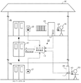
図1は、本発明の実施形態に係るエレベータ制御システム10と、このエレベータ制御システム10が設置されている高層のマンション20とを示す図である。マンション20は、複数の階層を有し、各階にはそれぞれ少なくとも1つの住戸を有する。マンション20の各階の移動にはエレベータが利用され、各階にはエレベータホールが備えられている。ユーザ30はエレベータホールの呼出ボタン21,22を操作してエレベータかご23を呼び出し、所望のフロアに移動する。
FIG. 1 is a diagram illustrating an
マンション20の1階は、受付やエントランスとして利用されている。また、マンション20の1階には、マンション20に出入りするためのエントランスドア24が設置されている。ユーザ30は、外からマンションに入る際に、鍵40を用いてエントランスドア24を開錠する。
The first floor of the
マンション20の2階以降は、マンション20の各ユーザ30の自宅として利用される。2階から上のフロアの廊下には、ユーザ30が自宅に出入りするための自宅用ドア25が配置される。ユーザ30は、エントランスドア24を施錠、開錠するのと同じ鍵40を用いて、自宅用ドア25を施錠や開錠する。なお、エントランスドア24と自宅用ドア25とで、異なる鍵40を使用するようにしてもよい。
The second floor and later of the
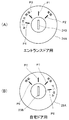
ここで、上述したドア(エントランスドア24、自宅用ドア25)の鍵穴周辺部分を拡大した図を図2に示す。
Here, the figure which expanded the keyhole periphery part of the door (
図2(A)は、エントランスドア24の鍵穴周辺部分を示した図である。マンション20から外に出た後、ユーザ30は鍵40をキーシリンダ24Aに設けられた鍵穴24Bに装填して、時計回りに鍵40を初期位置P1から施錠位置P2まで回転させてエントランスドア24を施錠(ロック)する。
また、外からマンション20に入る場合、ユーザ30は鍵40をキーシリンダ24Aの鍵穴24Bに装填して、反時計回りに鍵40を初期位置P1から開錠位置P3まで回転させてエントランスドア24を開錠させる。また、この際、マンション20の1階のエレベータホールにエレベータかご23を呼び出したい場合、ユーザ30は、装填された鍵40を開錠位置P3からさらに反時計回りに、かご呼出位置P4まで回転させる。
FIG. 2A is a view showing a portion around the keyhole of the
When entering the
図2(B)は、自宅用ドア25の鍵穴周辺部分を示した図である。自宅に入る場合、ユーザ30は鍵40をキーシリンダ25Aに設けられた鍵穴25Bに装填して、反時計回りに鍵40を初期位置P5から開錠位置P6まで回転させて自宅用ドア25を開錠させる。
また、自宅から廊下に出た後、ユーザ30は鍵40をキーシリンダ25Aの鍵穴25Bに装填して、時計回りに鍵40を初期位置P5から施錠位置P7まで回転させて自宅用ドア25を施錠(ロック)する。また、この際、自宅のあるn階のエレベータホールにエレベータかご23を呼び出したい場合、ユーザ30は、装填された鍵40を施錠位置P7からさらに反時計回りに、かご呼出位置P8まで回転させる。
FIG. 2 (B) is a view showing a portion around the keyhole of the
After exiting the hallway from home, the
図1に戻り、本発明の実施形態に係るエレベータ制御システム10は、キー位置検知部11,12と、エレベータ制御装置13とを備えて構成される。
Returning to FIG. 1, the
キー位置検知部11,12は、磁気センサなどから構成され、キー位置検知部11はエントランスドア24に、キー位置検知部12は自宅用ドア25の内部に設置される。キー位置検知部11,12は、キーシリンダ24A,25Aに装填された鍵40が図2(A)及び図2(B)に示すかご呼出位置P4、P8まで回転操作されたことを検知して、その検知信号を自身の識別情報とともにエレベータ制御装置13に出力する。
The key
図1に戻り、エレベータ制御装置13は、CPU(Central Processing Unit)やRAM(Random Access Memory)、ROM(Read Only Memory)等を備え、エレベータかご23の移動を制御するコンピュータである。
Returning to FIG. 1, the
続いて、エレベータ制御装置13の動作について、図3のフローチャートを参照して説明する。ユーザ30がエレベータホールの呼出ボタン21,22を操作してその操作信号を受信すると(ステップS11;Yes)、エレベータ制御装置13は、呼出ボタン21,22が操作された階にエレベータかご23を移動させる制御を行い(ステップS12)、ステップS11に処理は戻る。なお、ステップS12で実施する制御は、一般的なエレベータで行われているものと実質的に同じ制御である。
Next, the operation of the
また、エレベータ制御装置13は、キー位置検知部11,12から検知信号を受信すると(ステップS13;Yes)、この検知信号とともに受信したキー位置検知部11,12の識別情報から、このキー位置検知部11,12が設置されている階を特定する(ステップS14)。例えば、エレベータ制御装置13は、各キー位置検知部11,12の識別情報とキー位置検知部11,12が設置されている階数との対応関係が記憶されている所定のテーブルを参照することにより、階を特定すればよい。
Further, when the
続いて、エレベータ制御装置13は、特定した階にエレベータかご23を移動させる制御を行う(ステップS15)。例えば、エレベータ制御部13は、1階にあるエントランスドア24のキー位置検知部11から検知信号を受信した場合、エレベータかご23を1階に移動させる制御を行う。また、n階にある自宅用ドア25のキー位置検知部12から検知信号を受信した場合、エレベータ制御装置13は、エレベータかご23をn階に移動させる制御を行う。ステップS15の処理が終了すると、ステップS11に処理は戻る。
Subsequently, the
このように、本実施形態に係るエレベータ制御システム10によれば、エントランスドア24や自宅用ドア25の開錠や施錠をする際に鍵40をかご呼出位置P4、P8まで回転させることで、対応する階までエレベータかご23を呼び出すことができる。従って、エレベータかご23の到着待ち時間を短縮することができる。
Thus, according to the
また、本実施形態では、ドア(エントランスドア24、自宅用ドア25)を施錠、開錠するために使用する一般的な鍵40を利用してエレベータかご23を呼び出すため、エレベータかご23を呼び出すために専用の携帯端末等を用いる必要がなく、携帯端末の電池が切れて使用できなくなる虞もない。さらに、本実施形態では、施錠位置P2、P7、および、開錠位置P3、P6とは異なるかご呼出位置P4、P8に鍵40を回転させたときにエレベータかご23を呼び出す。従って、ユーザ30が自宅用ドア25を施錠したが、同じ階の他のユーザの自宅を訪問するだけであったり階段を利用したい等、エレベータかご23の呼び出しが不要な場合にまでエレベータかご23が呼び出されてしまうことを防ぐことができる。
Moreover, in this embodiment, in order to call the
また、本実施形態では、エントランスドア24のキーシリンダ24Aに装填された鍵40を回転させて開錠させた鍵40の開錠位置P3から、同じ方向にさらに鍵を回転させた操作を行うことで、エレベータかご23を呼び出す。従って、ユーザ30は、エントランスドア24の開錠からエレベータ呼び出しまでを直感的な操作で容易に行うことができる。
Further, in the present embodiment, an operation is performed in which the key is further rotated in the same direction from the unlocking position P3 of the key 40 that is unlocked by rotating the key 40 loaded in the
また、本実施形態では、自宅用ドア25のキーシリンダ25Aに装填された鍵40を回転させて施錠させた鍵40の施錠位置P7から、同じ方向にさらに鍵40を回転させた操作を行うことで、エレベータかご23を呼び出す。従って、ユーザ30は、自宅用ドア25の施錠からエレベータ呼び出しまでを直感的な操作で容易に行うことができる。
In the present embodiment, an operation is performed in which the key 40 is further rotated in the same direction from the locking position P7 of the key 40 that is locked by rotating the key 40 loaded in the
なお、本発明は、上記実施形態に限定されず、本発明の要旨を逸脱しない部分での種々の変更は勿論可能である。 In addition, this invention is not limited to the said embodiment, Of course, the various change in the part which does not deviate from the summary of this invention is possible.
例えば、図1に示すマンション20の例では、エントランスドア24と自宅用ドア25とは1つずつが示されているが、実際には、自宅用ドア25が複数あるのは勿論である。また、図1に示すようなマンション20に限らず、エレベータが利用される全ての建物に本発明は適用可能である。
For example, in the example of the
また、例えば、上記実施形態では、キーシリンダに装填してドアを施錠、開錠するタイプの鍵(物理キー)を使用する場合を例に説明した。しかしながら、様々なタイプの鍵に本発明を適用可能である。例えば、カードキーにも本発明は適用可能である。 Further, for example, in the above-described embodiment, the case where a key (physical key) of a type that is loaded into a key cylinder and locks and unlocks a door has been described as an example. However, the present invention can be applied to various types of keys. For example, the present invention can be applied to a card key.
ここで、カードキーを本発明に適用した場合について、図4を用いて具体的に説明する。この図において、自宅用ドア25の右側の壁には、カードキー50のタッチ操作を検出する施錠開錠部61とエレベータ呼出部62とがカード読取面が露出された状態で別々に埋め込まれている。なお、ユーザ30には、自宅用ドア25を施錠、開錠するための非接触タイプのカードキー50が予め与えられている。
Here, the case where the card key is applied to the present invention will be specifically described with reference to FIG. In this figure, a locking / unlocking
ユーザ30は、自宅用ドア25を施錠や開錠したい場合、カードキー50を施錠開錠部61にタッチする。タッチ操作を検知した施錠開錠部61は、自宅用ドア25の施錠や開錠を行う。
When the
また、ユーザ30は、自宅から外出するため等にエレベータを利用したい場合、カードキー50をエレベータ呼出部62にタッチする。タッチ操作を検知したエレベータ呼出部62は、前述のキー位置検知部11,12と同様に検知信号をエレベータ制御装置13に送信する。エレベータ制御装置13は、エレベータ呼出部62から検知信号を受信すると、対応する階にエレベータを移動させる。このように、カードキー50を利用した場合も、物理キー(鍵40)を利用した場合と同様に、施錠、開錠する操作とは別の操作により、エレベータかご23を呼び出すことが可能となる。なお、エレベータ呼出部62を設けずに施錠開錠部61のみを用いた場合、通常のタッチでは施錠や開錠のみを行い、連続的に複数回タッチをした場合にエレベータ制御装置13に検知信号を送信してエレベータかご23を呼び出すようにしてもよい。
In addition, when the
10 エレベータ制御システム
11,12 キー位置検知部
20 マンション
21,22 呼出ボタン
23 エレベータかご
24 エントランスドア
25 自宅用ドア
30 ユーザ
40 鍵
24A,25A キーシリンダ
24B,25B 鍵穴
P1,P5 初期位置
P2,P7 施錠位置
P3,P6 開錠位置
P4,P8 かご呼出位置
DESCRIPTION OF
Claims (3)
前記住戸のドアを開閉するための鍵による所定の操作を検知する鍵操作検知手段と、
前記鍵操作検知手段が所定の操作を検知した場合に、前記エレベータかごを該所定の操作が検知された階に移動させるエレベータ制御手段とを備え、
前記所定の操作は、前記ドアを施錠および開錠する操作とは異なる操作である、
ことを特徴とするエレベータ制御システム。 An elevator control system for controlling the movement of an elevator car installed in a building having at least one dwelling unit on multiple floors,
A key operation detecting means for detecting a predetermined operation by a key for opening and closing the door of the dwelling unit;
An elevator control means for moving the elevator car to the floor where the predetermined operation is detected when the key operation detecting means detects the predetermined operation;
The predetermined operation is an operation different from an operation of locking and unlocking the door.
An elevator control system characterized by that.
前記所定の回転位置は、前記ドアが施錠および開錠される回転位置とは異なる回転位置である、
ことを特徴とする請求項1に記載のエレベータ制御システム。 The key operation detection means detects that the key loaded in the key cylinder has been rotated to a predetermined rotation position as the predetermined operation,
The predetermined rotational position is a rotational position different from a rotational position where the door is locked and unlocked,
The elevator control system according to claim 1.
ことを特徴とする請求項2に記載のエレベータ制御システム。 The predetermined rotation position is a rotation position that is further rotated in the same direction from a rotation position in which the key loaded in the key cylinder is rotated to unlock or lock the door.
The elevator control system according to claim 2.
Priority Applications (1)
| Application Number | Priority Date | Filing Date | Title |
|---|---|---|---|
| JP2012145949A JP5980014B2 (en) | 2012-06-28 | 2012-06-28 | Elevator control system |
Applications Claiming Priority (1)
| Application Number | Priority Date | Filing Date | Title |
|---|---|---|---|
| JP2012145949A JP5980014B2 (en) | 2012-06-28 | 2012-06-28 | Elevator control system |
Publications (2)
| Publication Number | Publication Date |
|---|---|
| JP2014009059A true JP2014009059A (en) | 2014-01-20 |
| JP5980014B2 JP5980014B2 (en) | 2016-08-31 |
Family
ID=50106082
Family Applications (1)
| Application Number | Title | Priority Date | Filing Date |
|---|---|---|---|
| JP2012145949A Expired - Fee Related JP5980014B2 (en) | 2012-06-28 | 2012-06-28 | Elevator control system |
Country Status (1)
| Country | Link |
|---|---|
| JP (1) | JP5980014B2 (en) |
Cited By (1)
| Publication number | Priority date | Publication date | Assignee | Title |
|---|---|---|---|---|
| JP2025121312A (en) * | 2024-02-06 | 2025-08-19 | Nttドコモビジネス株式会社 | Information processing device, information processing method, information processing program, and information processing system |
Citations (5)
| Publication number | Priority date | Publication date | Assignee | Title |
|---|---|---|---|---|
| JPS63167435U (en) * | 1987-04-23 | 1988-11-01 | ||
| JPH04140285A (en) * | 1990-10-02 | 1992-05-14 | Toshiba Corp | Elevator |
| JPH04251080A (en) * | 1990-12-13 | 1992-09-07 | Mitsubishi Denki Bill Techno Service Kk | Call operation device for elevator |
| JPH09315706A (en) * | 1996-05-22 | 1997-12-09 | Kokusai Electric Co Ltd | Elevator calling device |
| JP2004043042A (en) * | 2002-07-08 | 2004-02-12 | Nippon Otis Elevator Co | Calling registration device for elevator |
-
2012
- 2012-06-28 JP JP2012145949A patent/JP5980014B2/en not_active Expired - Fee Related
Patent Citations (5)
| Publication number | Priority date | Publication date | Assignee | Title |
|---|---|---|---|---|
| JPS63167435U (en) * | 1987-04-23 | 1988-11-01 | ||
| JPH04140285A (en) * | 1990-10-02 | 1992-05-14 | Toshiba Corp | Elevator |
| JPH04251080A (en) * | 1990-12-13 | 1992-09-07 | Mitsubishi Denki Bill Techno Service Kk | Call operation device for elevator |
| JPH09315706A (en) * | 1996-05-22 | 1997-12-09 | Kokusai Electric Co Ltd | Elevator calling device |
| JP2004043042A (en) * | 2002-07-08 | 2004-02-12 | Nippon Otis Elevator Co | Calling registration device for elevator |
Cited By (2)
| Publication number | Priority date | Publication date | Assignee | Title |
|---|---|---|---|---|
| JP2025121312A (en) * | 2024-02-06 | 2025-08-19 | Nttドコモビジネス株式会社 | Information processing device, information processing method, information processing program, and information processing system |
| JP7743550B2 (en) | 2024-02-06 | 2025-09-24 | Nttドコモビジネス株式会社 | Information processing device, information processing method, information processing program, and information processing system |
Also Published As
| Publication number | Publication date |
|---|---|
| JP5980014B2 (en) | 2016-08-31 |
Similar Documents
| Publication | Publication Date | Title |
|---|---|---|
| CN105051795B (en) | Access control for the region with multiple leaf door | |
| CN107835778B (en) | Suppression Device Suppression Key | |
| AU2021323970B2 (en) | Building system with elevator call entry via offline QR code credential | |
| JP2015020888A (en) | Elevator control system and control method thereof | |
| JP5980014B2 (en) | Elevator control system | |
| JP5316340B2 (en) | Elevator system | |
| JP2009208900A (en) | Security system for elevator | |
| JP2003276958A (en) | Crime prevention device for elevator for apartment house | |
| JP4303747B2 (en) | Elevator control device | |
| JP2007223733A (en) | Elevator control system | |
| JP2010006551A (en) | Elevator control device | |
| JP2008230811A (en) | Fingerprint authentication system for elevator | |
| JP5929225B2 (en) | Entrance / exit management system | |
| JP5028335B2 (en) | Building integrated control system | |
| KR20160075151A (en) | System and method for providing an elevator movement service | |
| JP5407820B2 (en) | Elevator system | |
| JP4776267B2 (en) | Elevator remote control system | |
| CN101423159B (en) | Elevator control system | |
| JP2007246257A (en) | Security system of elevator | |
| JP2005324889A (en) | Elevator operation control system | |
| JP5172172B2 (en) | Elevator operation control system | |
| JP5529390B2 (en) | Automatic door unlocking system | |
| JP2010281060A (en) | Electronic key system | |
| JP2009214971A (en) | Elevator operation system | |
| JP2004043042A (en) | Calling registration device for elevator |
Legal Events
| Date | Code | Title | Description |
|---|---|---|---|
| A621 | Written request for application examination |
Free format text: JAPANESE INTERMEDIATE CODE: A621 Effective date: 20150108 |
|
| A977 | Report on retrieval |
Free format text: JAPANESE INTERMEDIATE CODE: A971007 Effective date: 20151116 |
|
| A131 | Notification of reasons for refusal |
Free format text: JAPANESE INTERMEDIATE CODE: A131 Effective date: 20151222 |
|
| A521 | Request for written amendment filed |
Free format text: JAPANESE INTERMEDIATE CODE: A523 Effective date: 20160212 |
|
| TRDD | Decision of grant or rejection written | ||
| A01 | Written decision to grant a patent or to grant a registration (utility model) |
Free format text: JAPANESE INTERMEDIATE CODE: A01 Effective date: 20160628 |
|
| A61 | First payment of annual fees (during grant procedure) |
Free format text: JAPANESE INTERMEDIATE CODE: A61 Effective date: 20160726 |
|
| R150 | Certificate of patent or registration of utility model |
Ref document number: 5980014 Country of ref document: JP Free format text: JAPANESE INTERMEDIATE CODE: R150 |
|
| R250 | Receipt of annual fees |
Free format text: JAPANESE INTERMEDIATE CODE: R250 |
|
| R250 | Receipt of annual fees |
Free format text: JAPANESE INTERMEDIATE CODE: R250 |
|
| R250 | Receipt of annual fees |
Free format text: JAPANESE INTERMEDIATE CODE: R250 |
|
| R250 | Receipt of annual fees |
Free format text: JAPANESE INTERMEDIATE CODE: R250 |
|
| LAPS | Cancellation because of no payment of annual fees |