JP2014015843A - 内燃機関 - Google Patents
内燃機関 Download PDFInfo
- Publication number
- JP2014015843A JP2014015843A JP2012151596A JP2012151596A JP2014015843A JP 2014015843 A JP2014015843 A JP 2014015843A JP 2012151596 A JP2012151596 A JP 2012151596A JP 2012151596 A JP2012151596 A JP 2012151596A JP 2014015843 A JP2014015843 A JP 2014015843A
- Authority
- JP
- Japan
- Prior art keywords
- cavity
- head
- fuel
- spray
- combustion chamber
- Prior art date
- Legal status (The legal status is an assumption and is not a legal conclusion. Google has not performed a legal analysis and makes no representation as to the accuracy of the status listed.)
- Granted
Links
Images




Classifications
-
- Y—GENERAL TAGGING OF NEW TECHNOLOGICAL DEVELOPMENTS; GENERAL TAGGING OF CROSS-SECTIONAL TECHNOLOGIES SPANNING OVER SEVERAL SECTIONS OF THE IPC; TECHNICAL SUBJECTS COVERED BY FORMER USPC CROSS-REFERENCE ART COLLECTIONS [XRACs] AND DIGESTS
- Y02—TECHNOLOGIES OR APPLICATIONS FOR MITIGATION OR ADAPTATION AGAINST CLIMATE CHANGE
- Y02T—CLIMATE CHANGE MITIGATION TECHNOLOGIES RELATED TO TRANSPORTATION
- Y02T10/00—Road transport of goods or passengers
- Y02T10/10—Internal combustion engine [ICE] based vehicles
- Y02T10/12—Improving ICE efficiencies
Landscapes
- Combustion Methods Of Internal-Combustion Engines (AREA)
Abstract
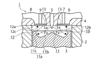
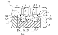
【解決手段】ピストン3の頂部に凹設され燃焼室10の一部を形成するキャビティ11と、キャビティ11に対向するシリンダヘッド4のヘッド面12に配置され、キャビティ11の壁面11aに、周方向xに間隔を隔てて複数の燃料の噴霧Fを噴射するインジェクタ5と、を備え、ヘッド面12の、インジェクタ5から噴射された噴霧Fがキャビティ11の壁面11aに衝突した後に到達する部分に位置して設けられ、燃焼室10の内外方向yに沿って形成された複数のヘッド用溝13を備える。
【選択図】図2
Description
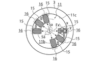
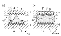
11aに、各噴霧Fが衝突する部分に位置して、キャビティ11の内外方向y(図10の(a)における紙面裏表方向であり、図10の(b)における紙面上下方法)に沿ったキャビティ用溝15を複数形成した燃焼室10Xを備える装置(例えば、特許文献2参照)を考案した。
下面、及び排気バルブの下面を含む面のことであり、ヘッド用溝群を、シリンダヘッドの下面、吸気バルブの下面、及び排気バルブの下面などを問わず、燃料の噴霧が到達する部分に設けるとよい。
バルブ7の下面12b、及び排気バルブ9の下面12cを含み、キャビティ11に対向するシリンダヘッド4のヘッド面12の中心部から外周に向けて、形成してもよいが、図2に示すように、ヘッド面12の中心部近傍を除いて同様に形成してもよい。要は、ヘッド用溝13は、ヘッド面12内の少なくとも燃料が到達する部分に形成されていればよい。
ては複数のヘッド用溝13に邪魔され相対的に抵抗が高いので広がりが抑えられる。
2 シリンダ
3 ピストン
4 シリンダヘッド
5 インジェクタ
6 吸気ポート
7 吸気バルブ
8 排気ポート
9 排気バルブ
10 燃焼室
11 キャビティ
12 ヘッド面
13 ヘッド用溝
14 ヘッド用溝群
15 キャビティ用溝
16 キャビティ用溝群
Claims (4)
- ピストンの頂部に凹設され燃焼室の一部を形成するキャビティと、前記キャビティに対向するシリンダヘッドのヘッド面に配置され、前記キャビティの壁面に、周方向に間隔を隔てて複数の燃料の噴霧を噴射するインジェクタと、を備える内燃機関において、
前記ヘッド面の、前記インジェクタから噴射された前記噴霧が前記キャビティの壁面に衝突した後に到達する部分に位置して設けられ、前記燃焼室の内外方向に沿って形成された複数のヘッド用溝を備えることを特徴とする内燃機関。 - 前記ヘッド用溝を、前記インジェクタから前記キャビティに向けて噴射される燃料の噴射方向に対し、平行に形成することを特徴とする請求項1に記載の内燃機関。
- 前記キャビティの壁面に、前記噴霧が衝突する部分に位置して設けられ、前記キャビティの内外方向に沿って形成された複数のキャビティ用溝を備え、
前記ヘッド用溝と前記キャビティ用溝を対向一致するように配置することを特徴とする請求項1又は2に記載の内燃機関。 - 前記インジェクタからの燃料の噴射時期を、前記ピストンの圧縮上死点よりも早期にして、前記燃料の噴射完了後に着火する予混合圧縮着火燃焼を行う運転領域を有することを特徴とする請求項1〜3のいずれか1項に記載の内燃機関。
Priority Applications (1)
| Application Number | Priority Date | Filing Date | Title |
|---|---|---|---|
| JP2012151596A JP5983109B2 (ja) | 2012-07-05 | 2012-07-05 | 内燃機関 |
Applications Claiming Priority (1)
| Application Number | Priority Date | Filing Date | Title |
|---|---|---|---|
| JP2012151596A JP5983109B2 (ja) | 2012-07-05 | 2012-07-05 | 内燃機関 |
Publications (2)
| Publication Number | Publication Date |
|---|---|
| JP2014015843A true JP2014015843A (ja) | 2014-01-30 |
| JP5983109B2 JP5983109B2 (ja) | 2016-08-31 |
Family
ID=50110758
Family Applications (1)
| Application Number | Title | Priority Date | Filing Date |
|---|---|---|---|
| JP2012151596A Expired - Fee Related JP5983109B2 (ja) | 2012-07-05 | 2012-07-05 | 内燃機関 |
Country Status (1)
| Country | Link |
|---|---|
| JP (1) | JP5983109B2 (ja) |
Cited By (5)
| Publication number | Priority date | Publication date | Assignee | Title |
|---|---|---|---|---|
| JP2018087507A (ja) * | 2016-11-28 | 2018-06-07 | マツダ株式会社 | エンジンの燃焼室構造 |
| JP2018087508A (ja) * | 2016-11-28 | 2018-06-07 | マツダ株式会社 | エンジンの燃焼室構造 |
| JP2019002289A (ja) * | 2017-06-12 | 2019-01-10 | マツダ株式会社 | エンジンの燃焼室 |
| JP2019002288A (ja) * | 2017-06-12 | 2019-01-10 | マツダ株式会社 | エンジンの燃焼室 |
| JP2025045964A (ja) * | 2023-09-21 | 2025-04-02 | いすゞ自動車株式会社 | 内燃機関 |
Citations (2)
| Publication number | Priority date | Publication date | Assignee | Title |
|---|---|---|---|---|
| JPS6295130U (ja) * | 1985-12-04 | 1987-06-17 | ||
| JP2010285907A (ja) * | 2009-06-10 | 2010-12-24 | Isuzu Motors Ltd | 内燃機関 |
-
2012
- 2012-07-05 JP JP2012151596A patent/JP5983109B2/ja not_active Expired - Fee Related
Patent Citations (2)
| Publication number | Priority date | Publication date | Assignee | Title |
|---|---|---|---|---|
| JPS6295130U (ja) * | 1985-12-04 | 1987-06-17 | ||
| JP2010285907A (ja) * | 2009-06-10 | 2010-12-24 | Isuzu Motors Ltd | 内燃機関 |
Cited By (6)
| Publication number | Priority date | Publication date | Assignee | Title |
|---|---|---|---|---|
| JP2018087507A (ja) * | 2016-11-28 | 2018-06-07 | マツダ株式会社 | エンジンの燃焼室構造 |
| JP2018087508A (ja) * | 2016-11-28 | 2018-06-07 | マツダ株式会社 | エンジンの燃焼室構造 |
| JP2019002289A (ja) * | 2017-06-12 | 2019-01-10 | マツダ株式会社 | エンジンの燃焼室 |
| JP2019002288A (ja) * | 2017-06-12 | 2019-01-10 | マツダ株式会社 | エンジンの燃焼室 |
| JP2025045964A (ja) * | 2023-09-21 | 2025-04-02 | いすゞ自動車株式会社 | 内燃機関 |
| JP7726251B2 (ja) | 2023-09-21 | 2025-08-20 | いすゞ自動車株式会社 | 内燃機関 |
Also Published As
| Publication number | Publication date |
|---|---|
| JP5983109B2 (ja) | 2016-08-31 |
Similar Documents
| Publication | Publication Date | Title |
|---|---|---|
| JP4888330B2 (ja) | 直接噴射式の内燃機関 | |
| JP6088016B1 (ja) | ピストン | |
| JP6869244B2 (ja) | 内燃機関のピストンクラウン | |
| JP5589453B2 (ja) | ディーゼルエンジンの燃焼室 | |
| JP6088015B1 (ja) | 燃料噴射装置 | |
| US9885277B2 (en) | Compression-ignition direct-injection combustion engine and fuel injection method for same | |
| US9970350B2 (en) | Opposed piston engine with pistons having conical recesses therein | |
| JP5584673B2 (ja) | 内燃機関 | |
| JP5983109B2 (ja) | 内燃機関 | |
| US10731544B2 (en) | Internal combustion engine and method for its operation | |
| US20160201551A1 (en) | Combustion chamber structure for engine | |
| JP5671809B2 (ja) | 内燃機関の燃焼室構造 | |
| CN112567121A (zh) | 机动车用内燃机的运行方法以及机动车用内燃机 | |
| KR20200069920A (ko) | 엔진의 피스톤 연소실구조 | |
| JP5671810B2 (ja) | 内燃機関の燃焼室構造 | |
| JP5983110B2 (ja) | 内燃機関 | |
| JP2010285907A (ja) | 内燃機関 | |
| JP6213285B2 (ja) | 燃料噴射弁 | |
| JP6019831B2 (ja) | 内燃機関 | |
| JP5071090B2 (ja) | ディーゼルエンジンの燃料噴射方法及びディーゼルエンジン | |
| JP5136255B2 (ja) | 火花点火式直噴エンジン | |
| JP2008082193A (ja) | 燃料噴射ノズル | |
| JP2005140006A (ja) | 筒内直接噴射式内燃機関 | |
| JP2011117319A (ja) | 直接噴射式ディーゼルエンジンの燃焼室構造 | |
| JP5418315B2 (ja) | ディーゼルエンジンの燃焼室 |
Legal Events
| Date | Code | Title | Description |
|---|---|---|---|
| A621 | Written request for application examination |
Free format text: JAPANESE INTERMEDIATE CODE: A621 Effective date: 20150629 |
|
| A977 | Report on retrieval |
Free format text: JAPANESE INTERMEDIATE CODE: A971007 Effective date: 20160328 |
|
| A131 | Notification of reasons for refusal |
Free format text: JAPANESE INTERMEDIATE CODE: A131 Effective date: 20160405 |
|
| A521 | Request for written amendment filed |
Free format text: JAPANESE INTERMEDIATE CODE: A523 Effective date: 20160426 |
|
| TRDD | Decision of grant or rejection written | ||
| A01 | Written decision to grant a patent or to grant a registration (utility model) |
Free format text: JAPANESE INTERMEDIATE CODE: A01 Effective date: 20160705 |
|
| A61 | First payment of annual fees (during grant procedure) |
Free format text: JAPANESE INTERMEDIATE CODE: A61 Effective date: 20160718 |
|
| R150 | Certificate of patent or registration of utility model |
Ref document number: 5983109 Country of ref document: JP Free format text: JAPANESE INTERMEDIATE CODE: R150 |
|
| LAPS | Cancellation because of no payment of annual fees |